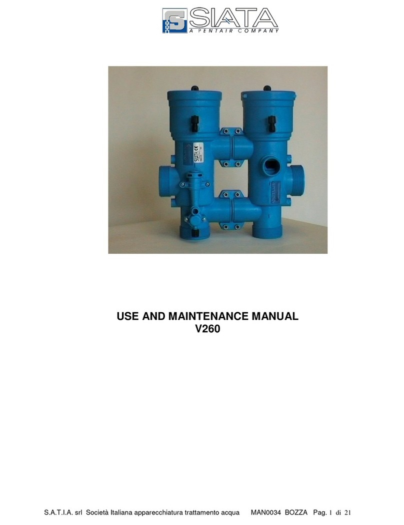
SIATA V360 User manual

S.I.A.T.A. S.r.l Società Italiana apparecchiature trattamento acqua MAN0031 BOZZA Pag. 1 of 25
USE AND MAINTENANCE MANUAL
V360

S.I.A.T.A. S.r.l Società Italiana apparecchiature trattamento acqua MAN0031 BOZZA Pag. 2 of 25
Document Revision Revision note Date
MAN0031 A Draft

S.I.A.T.A. S.r.l Società Italiana apparecchiature trattamento acqua MAN0031 BOZZA Pag. 3 of 25
INDEX
GENERAL CHARACTERISTICS – TECHNICAL SPECIFICATIONS 4
COUNTERCURRENT AND FAST RINSE LOADS 5
DIMENSIONS 6
FUNCTIONAL DIAGRAMS 7-9
FUNCTIONAL DIAGRAMS (with countercurrent flow regulator) 10
USE VARIATIONS 11-13
USE SPECIFICATIONS 14
VALVE/TIMER CONNECTIONS 15-18
INJECTOR TABLES 19
FLOW CONTROL PREVIEW V360 20
TIMERCHOICETABLE 21
BASIC VALVE COMPONENTS SOFTENING AND DEMINERAL. 22
BASIC STANDARD FILTER COMPONENTS 23
NORMAL MAINTENANCE OPERATIONS 24

S.I.A.T.A. S.r.l Società Italiana apparecchiature trattamento acqua MAN0031 BOZZA Pag. 4 of 25
GENERAL CHARACTERISTICS – TECHNICAL SPECIFICATIONS
The “360” valves represent an essential element for the realisation of systems of various types and for
various uses.
Softening – single, duplex, or on more columns for domestic industrial or laboratory use.
Demineralisation and decarbonisation – single, duplex, for laboratory and industrial use and for all uses
which require water with guaranteed quality characteristics.
Filtration – single or duplex for all applications shown above.
The valves are made from materials which guarantee the maximum durability and quality.
The valves are available with a wide range of timers, for the control of all operative phases of service and
regeneration, from the simplest electromechanical timer with a weekly timer, to the sophisticated electronic
timers in various models which allow for volume and volume/time controls, controls of salinity in
microsiemens/cm etc.
With the electronic systems, all the times of the operative phase operations are programmable, relative to
the type and dimensions of the system.
For the specific characteristics of the timers, see the relevant manual.
TECHNICAL SPECIFICATIONS
Running pressure : 2 - 6 bar
Max. Running load : 45m3/h
For variables of the value see graph : -
Countercurrent rinse load : max. 12 m3/h
Equicurrent fast rinse load : 480-1300 l/h
Equicurrent fast rinse load : max. 18 m3/h
Static resistance to pressure : 22 bar
Max quantity regenerable resin : 1200 l.
Running temperature : 5 - 40° c
Basic materials of principal components : abs + fv
Entry/exit attachments : 2” female gas
LOAD LOSS GRAPH

S.I.A.T.A. S.r.l Società Italiana apparecchiature trattamento acqua MAN0031 BOZZA Pag. 5 of 25
COUNTERCURRENT LOAD GRAPH
FAST RINSE LOAD GRAPH

S.I.A.T.A. S.r.l Società Italiana apparecchiature trattamento acqua MAN0031 BOZZA Pag. 6 of 25
DIMENSIONS
1Connection for cylinder opening
Top column
6 Exit
2Connection for cylinder closure
Top column
7 Connection top column
3Connection for cylinder opening
bottom column
8 Connection bottom column
4Connection for cylinder closure
bottom column
9 Connection for suction Ø 1”
5Entry 10 Connection for male drain Ø ISO 40
11 Connection for pilot timer control
364-A 1” ½ GAS
364-B 2” GAS
364-C 2” ½ GAS
364-D 3” GAS
364-E01 ISO 50 GLUED
364-F01 ISO 63 GLUED
364-G01 ISO 75 GLUED
364-N01 Ø60.4 GLUED
364-P01 3” NPT GLUED

S.I.A.T.A. S.r.l Società Italiana apparecchiature trattamento acqua MAN0031 BOZZA Pag. 7 of 25
FUNCTIONAL DIAGRAMS

S.I.A.T.A. S.r.l Società Italiana apparecchiature trattamento acqua MAN0031 BOZZA Pag. 8 of 25
FUNCTIONAL DIAGRAMS

S.I.A.T.A. S.r.l Società Italiana apparecchiature trattamento acqua MAN0031 BOZZA Pag. 9 of 25
FUNCTIONAL DIAGRAMS

S.I.A.T.A. S.r.l Società Italiana apparecchiature trattamento acqua MAN0031 BOZZA Pag. 10 of
25
FUNCTIONAL DIAGRAMS

S.I.A.T.A. S.r.l Società Italiana apparecchiature trattamento acqua MAN0031 BOZZA Pag. 11 of
25
VARIATIONS FOR SINGLE
SYSTEMS USE

S.I.A.T.A. S.r.l Società Italiana apparecchiature trattamento acqua MAN0031 BOZZA Pag. 12 of
25
VARIATIONS FOR DUPLEX
SYSTEMS USE

S.I.A.T.A. S.r.l Società Italiana apparecchiature trattamento acqua MAN0031 BOZZA Pag. 13 of
25
VARIATIONS FOR
DEMINERALISATION AND FILTRATION SYSTEMS USE

S.I.A.T.A. S.r.l Società Italiana apparecchiature trattamento acqua MAN0031 BOZZA Pag. 14 of
25
USE SPECIFICATIONS
Referring to the paragraph VERSIONS seen above, the various possibilities for the uses of this
valve in the various applications may be examined.
1) Single softening: the system consists of a basic valve V360A-05/05 with or without bypass,
and a timer complete with a minimum of 2 external pilots in different solutions, with which the
system may be personalised as desired.
In particular, varying the number of external pilots, it is possible to obtain the following
personalisations:
I. 2 pilots controls only the movement of the pistons of the valve
II. 3 pilots controls also an additional use closure valve
III. 4 pilots controls a use closure + a suction closure
2) duplex softening: the system is made on two columns, each of which is run by a V360A-05/05
valve. This is controlled, with water or air, by a timer with a minimum of 2 pilots per valve. The
alternating duplex systems (one column is in service while the other is in regeneration or not in
use), may be controlled by the AQUA CUBIC timer, which may be supplied in two standard
versions:
I. 5 pilots (AC5-02/05), run by volume. The system allows for use of two brine
valves plus a use closure valve
II. As a variation on this system, it is possible to substitute the two brine valves
with two on-off hidro-pneumatic valves for the closing/opening of the suction
duct(see valve V1 page 10), using an AQUA CUBIC 7-pilot timer. (AC7-
02/05)
3) Demineralisation and Decarbonisation: this is the applicative sector in which the
characteristics of the V360 valve may be best appreciated in the models V360D-04/05 & V360D-
05/05. The timer predisposed for demineralisation is electronic with external pilots, capable of
controlling an anionic and cationic column, can control the level of conductibility showing a valve in
µsiemens/cm at the exit of the system, and regenerate the system automatically. The number of
pilots of the timer is determined by the type of system required
I. AQUA IONIC 5 pilots ( AI5-02/05 ) controls the two columns + an on-off hydro-
pneumatic use closure valve
II. AQUA IONIC 7 pilots ( AI7-02/05 ) controls the two columns+ an on-off hydro-
pneumatic use closure valve+ two on-off hydro-pneumatic valves for the
closing/opening of the regenerator suction.
4) Filtration: the considerations made regarding softening are valid both for single and duplex
systems, with the exception that in this case the suction of the regenerator does not need to be
controlled.
. For further details regarding the timers, see the table of timer choice (page 23).

S.I.A.T.A. S.r.l Società Italiana apparecchiature trattamento acqua MAN0031 BOZZA Pag. 15 of
25
VALVE/TIMER CONNECTIONS

S.I.A.T.A. S.r.l Società Italiana apparecchiature trattamento acqua MAN0031 BOZZA Pag. 16 of
25
VALVE/ TIMER CONNECTIONS

S.I.A.T.A. S.r.l Società Italiana apparecchiature trattamento acqua MAN0031 BOZZA Pag. 17 of
25
VALVE / TIMER CONNECTIONS

S.I.A.T.A. S.r.l Società Italiana apparecchiature trattamento acqua MAN0031 BOZZA Pag. 18 of
25
VALVE / TIMER CONNECTIONS

S.I.A.T.A. S.r.l Società Italiana apparecchiature trattamento acqua MAN0031 BOZZA Pag. 19 of
25
INJECTOR TABLES V360

S.I.A.T.A. S.r.l Società Italiana apparecchiature trattamento acqua MAN0031 BOZZA Pag. 20 of
25
FLOW CONTROL V360
PREVIEW
Table of contents
Other SIATA Control Unit manuals
