SIATA V260 User manual

S.A.T.I.A. srl Società Italiana apparecchiatura trattamento acqua MAN0034 BOZZA Pag. 1 di 21
USE AND MAINTENANCE MANUAL
V260
S.A.T.I.A. srl Società Italiana apparecchiatura trattamento acqua MAN0034 BOZZA Pag. 2 di 21
DOCUMENT REVISION REVISION NOTE DATE
MAN0034 DRAFT

S.A.T.I.A. srl Società Italiana apparecchiatura trattamento acqua MAN0034 BOZZA Pag. 3 di 21
INDEX
GENERAL CHARACTERISTICS .................................................................................................................................4
RUNNING LOAD .............................................................................................................................................................4
RINSE LOAD IN COUNTERCURRENT ......................................................................................................................5
FAST RINSE LOAD .....................................................................................................................................................5
DIMENSIONS...................................................................................................................................................................6
FLOW DIAGRAM ...........................................................................................................................................................7
VERSIONS ........................................................................................................................................................................9
USE SPECIFICATIONS ................................................................................................................................................11
TIMER – VALVE CONNECTIONS.............................................................................................................................12
FLOW CONTROL SYSTEMS......................................................................................................................................16
V260 BASIC COMPONENTS .......................................................................................................................................17
V260 INJECTOR ............................................................................................................................................................18
SPARE PARTS ...............................................................................................................................................................19
TIMER .............................................................................................................................................................................20
MAINTENANCE ADVISE ............................................................................................................................................21
S.A.T.I.A. srl Società Italiana apparecchiatura trattamento acqua MAN0034 BOZZA Pag. 4 di 21
GENERAL CHARACTERISTICS
The “V260” valves represent an essential element for the realisation of systems of various types and for
various uses
a) SOFTENING (decalcification)- single, duplex or on more columns for domestic or industrial use
b) DEMINERALISATION single o duplex, for all uses which require water with guaranteed quality
characteristics.
The valves are made from materials which guarantee the maximum durability and quality.
The valves are available with a wide range of timers, for the control of all operative phases of service and
regeneration. These sophisticated electronic timers in the various models;by time, by volume, by
volume/time, allow for the programming of all operative phases of water treatment systems covered by the
types specified .
TECHNICAL SPECIFICATIONS
Running pression : 1.5 - 6 bar
Running load : 21 mc/h
Countercurrent rinse load : 12 mc/h
Slow rinse load : 300 - 1000 l/h
Equicurrent fast rinse load : 14 mc/h
Static resistance to pressure : 22 bar
Max.quantity regenerable resin : 500 l
Running temperature : 5 - 40°c
Basic materials of principal components : abs + fv
Entry/exit attachments : 2” ¼ male gas
RUNNING LOAD

S.A.T.I.A. srl Società Italiana apparecchiatura trattamento acqua MAN0034 BOZZA Pag. 5 di 21
RINSE LOAD IN COUNTERCURRENT
FAST RINSE LOAD

S.A.T.I.A. srl Società Italiana apparecchiatura trattamento acqua MAN0034 BOZZA Pag. 6 di 21
DIMENSIONS
S.A.T.I.A. srl Società Italiana apparecchiatura trattamento acqua MAN0034 BOZZA Pag. 7 di 21
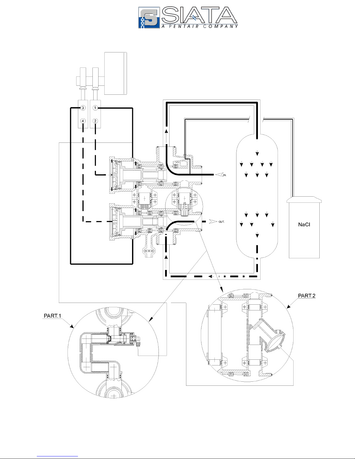
FLOW DIAGRAM
SERVIZIO / SERVICE

S.A.T.I.A. srl Società Italiana apparecchiatura trattamento acqua MAN0034 BOZZA Pag. 8 di 21

S.A.T.I.A. srl Società Italiana apparecchiatura trattamento acqua MAN0034 BOZZA Pag. 9 di 21
VERSIONS

S.A.T.I.A. srl Società Italiana apparecchiatura trattamento acqua MAN0034 BOZZA Pag. 10 di 21

S.A.T.I.A. srl Società Italiana apparecchiatura trattamento acqua MAN0034 BOZZA Pag. 11 di 21
USE SPECIFICATIONS
Referring to the paragraph “VERSIONS” seen above, the various possibilities for the uses of this
valve in the various applications may be examined.
1) Single softening: the system consists of a basic valve V260A-?/05 (the question mark should
be substituted with the colour of the injector required), and a timer complete with a minimum of 2
external pilots in different solutions, with which the system may be personalised as desired.
In particular, varying the number of external pilots, it is possible to obtain the following
personalisations:
I. 2 pilots controls only the movement of the pistons of the valve
II. 3 pilots also controls an additional use closure valve
III. 4 pilots controls a use closure + a suction closure
2) Duplex softening: the system is made on two columns, each of which is run by a V260A-?/05.
This is controlled, with water or air, by a timer with a minimum of 2 pilots per valve.
The alternating duplex systems (one column is in service while the other is in regeneration or not in
use), may be controlled by the AQUA CUBIC timer, which may be supplied in two standard
versions:
I. 5 pilots (AC5-02/05), run by volume. The system allows for the use of two brine valves plus
a use closure valve
II. As a variation on this system, it is possible to substitute the two brine valves with two on-off
hydro-pneumatic valves for the closing/opening of the suction duct, using an AQUA CUBIC
7-pilot timer . (AC7-02/05)
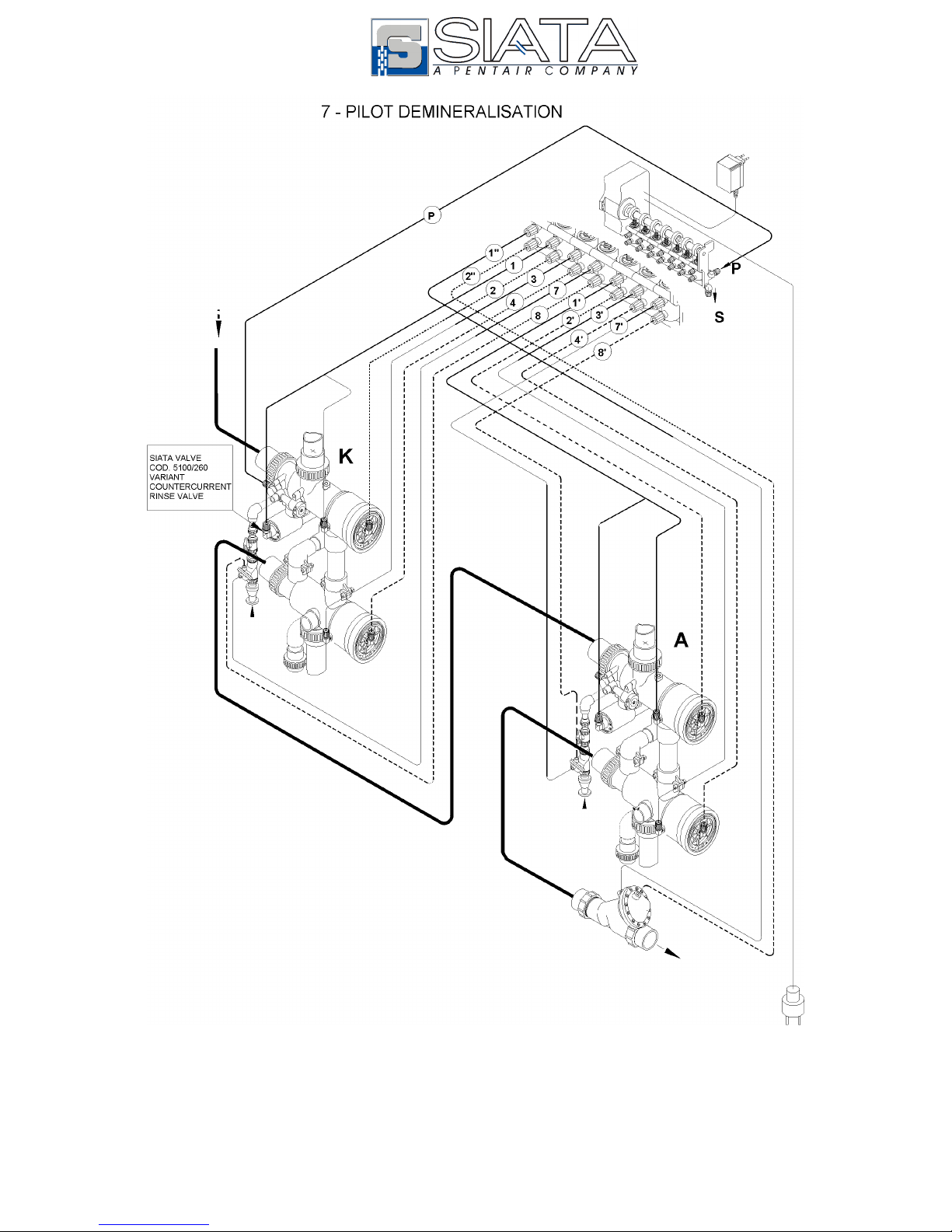
1) Demineralisation and Decarbonisation: this is the applicative sector in which the
characteristics of the V260 valve may be best appreciated. In particular the V260 for
demineralisation is supplied in two different solutions: (see the demineralisation versions page
10)
A) The V260D consists of a separated top column and base column, both however supplied
with a two Ø 1” connectors, allowing the installer the possibility to choose the length of the
most suitable connecting pipe.
B) The V260D-BV with backwash valve, (eliminites bypass water during regeneration)
consists of a top and base column, as well as kit 5100-260. Also in this case, the definitive
connection between the two parts must be carried out by the installer.
The timer predisposed for demineralisation is electronic with external pilots, capable of controlling
an anionic and cationic column, can control the level of conductibility showing a valve in
µsiemns/cm at the exit of the system, and regenerate the system automatically. The number of
pilots of the timer is determined by the type of system required
I. AQUA IONIC 5 pilots ( AI5-02/05 ) controls the two columns + an on-off hydro-pneumatic
use closure valve
II. AQUA IONIC 7 piloti ( AI7-02/05 ) controls the two columns + an on-off hydro-pneumatic
use closure valve+ two on-off hydro-pneumatic valves for the closing/opening of the
regenerator suction.
4) Filtration: the considerations made regarding softening are valid both for single and duplex
system, with the exception that in this case the suction of the regenerator does not need to be
controlled.
. For further details regarding the timers, see the table of timer choice (pag. 21)
N.B. Among the accessories of the V260, note the kit code 5100-260 of the backwash valve, the
bypass of unpurified water towards use, during the regeneration phase, can be avoided.

S.A.T.I.A. srl Società Italiana apparecchiatura trattamento acqua MAN0034 BOZZA Pag. 12 di 21
TIMER – VALVE CONNECTIONS

S.A.T.I.A. srl Società Italiana apparecchiatura trattamento acqua MAN0034 BOZZA Pag. 13 di 21

S.A.T.I.A. srl Società Italiana apparecchiatura trattamento acqua MAN0034 BOZZA Pag. 14 di 21
S.A.T.I.A. srl Società Italiana apparecchiatura trattamento acqua MAN0034 BOZZA Pag. 15 di 21

S.A.T.I.A. srl Società Italiana apparecchiatura trattamento acqua MAN0034 BOZZA Pag. 16 di 21
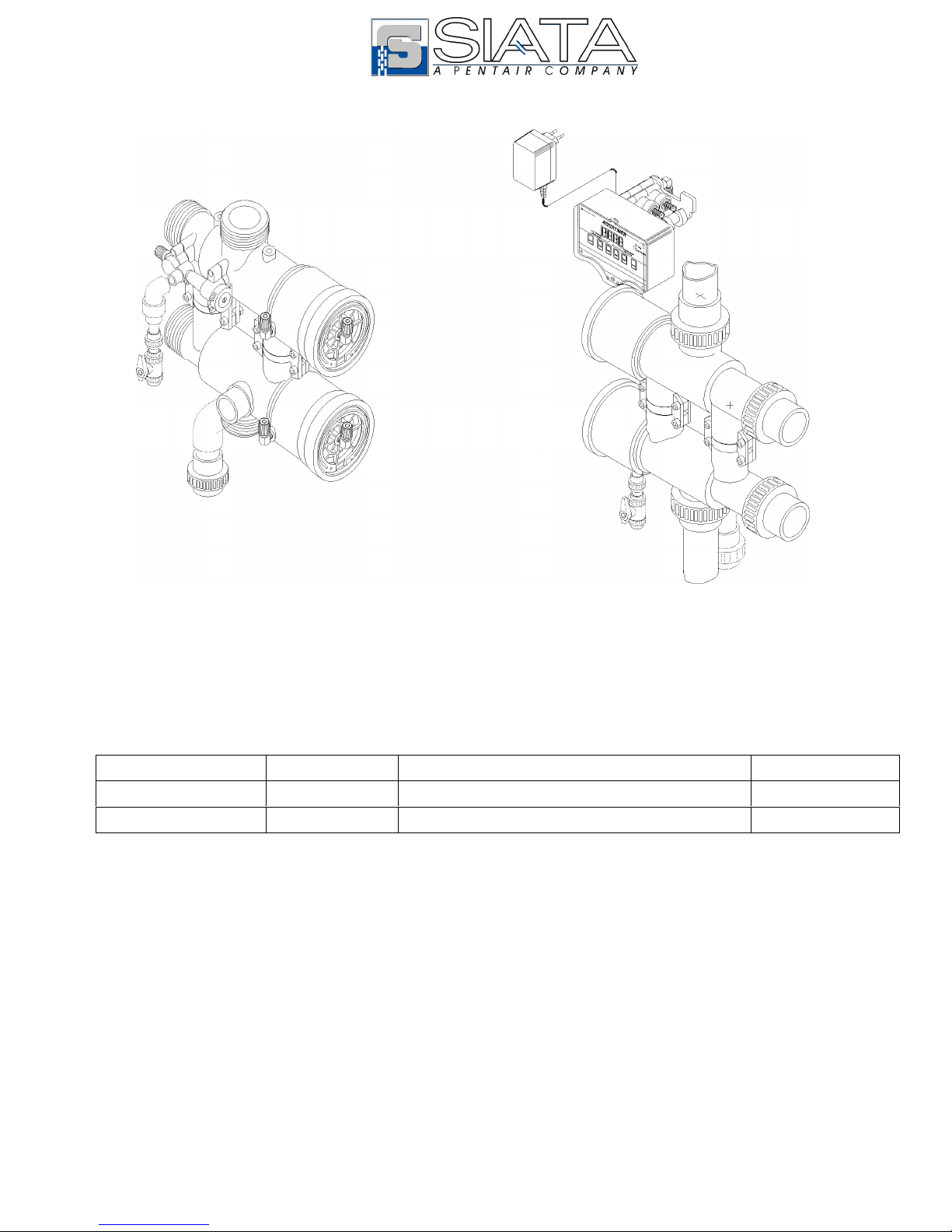
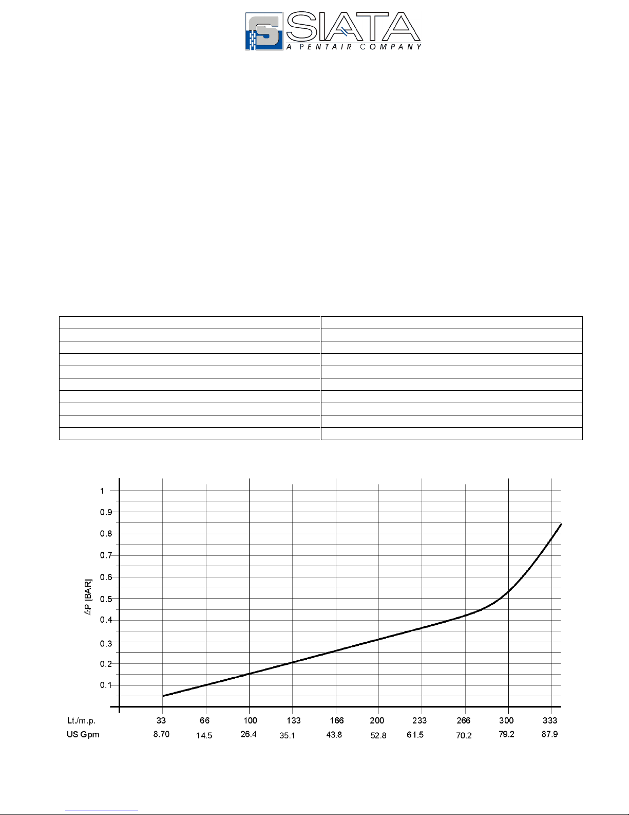
FLOW CONTROL SYSTEMS
The S.I.A.T.A. flow control system is composed of 3 parts, see page 1:
1. The flow delivery with 2 or 4 drill holes cod. 5124 or 5124-4
2. The flow cod. 70-* (with various dimensions)
3. The flow delivery part cod 5228
In the solution proposed in fig. 3, it may be operated easily as a drain flow control of a V250 valve using a
normal adaptor Ø 40 ISO F – 1” ½ G.F..
The solution in fig.1 may be used instead as a flow control of the countercurrent, see fig.4. For the
calculation of the load which are to be controlled, see the table below.

S.A.T.I.A. srl Società Italiana apparecchiatura trattamento acqua MAN0034 BOZZA Pag. 17 di 21
V260 BASIC COMPONENTS

S.A.T.I.A. srl Società Italiana apparecchiatura trattamento acqua MAN0034 BOZZA Pag. 18 di 21
V260 INJECTOR

S.A.T.I.A. srl Società Italiana apparecchiatura trattamento acqua MAN0034 BOZZA Pag. 19 di 21
SPARE PARTS
Pos. Code Description
1 5120-L V250-V260 A/C Machined body
2 5121-L V250-V260 B/C machined body
3 5141 V250- 260 piston
4 5110-AC A/C V250 – 260 linings set
5 5110-BC B/C V250 – 260 linings set
6 5150-B V250- 260 blu injector set
5150-N V250- 260 black injector set
5150-F V250- 260 filter injector set
7 5160 V250-260 complete mobile valve set
8 5180-SC V250 A/B column ring set
9 5100-250 V250 complete backwash valve
10 5130 Stopper set V250-260
11 5200-A Under valve filter for V250A (0.3 mm)
5200-F Under valve filter for V250F (0.8 mm)
12 5201-A Base filter for V250A (0.3 mm)
5201-F Base filter for V250F (0.8 mm)

S.A.T.I.A. srl Società Italiana apparecchiatura trattamento acqua MAN0034 BOZZA Pag. 20 di 21
TIMER
Table of contents
Other SIATA Control Unit manuals


