SIBS Fuso Canter Instruction manual

SIBS® 4 WORKSHOP MANUAL
FUSO CANTER

MAN-059 8 FEB 2017
2
1. Revision History
Revision
Issue Date
Author
Comments
1
1 Mar 2016
M. O’Driscoll
Initial Release
2
8 Feb 2017
M. O’Driscoll
Sections 14, 15, 16 and 17 updated with new service regime.
3
6 Apr 2017
M. O’Driscoll
Wiring and hydraulic sections updated with 24V details.
© Advanced Braking Pty Ltd, 2017.
All rights reserved. No part of this manual may be reproduced in any form or by any means without the prior written consent
from the copyright holder. While every attempt is made to ensure that the information in this manual is correct, no liability can
be accepted by the authors for loss, damage or injury caused by any errors in, or omissions from, the information given.

MAN-059 8 FEB 2017
3
2. Table of Contents
1. Revision History ....................................................................................................................................................................... 2
2. Table of Contents..................................................................................................................................................................... 3
3. Important Information ............................................................................................................................................................ 4
4. Terminology............................................................................................................................................................................. 5
5. Brake Description .................................................................................................................................................................... 6
6. Exploded Views & Parts Lists - Differential Brake Assembly ................................................................................................... 7
7. Wiring Diagram 12V............................................................................................................................................................... 10
8. Wiring Diagram 24V............................................................................................................................................................... 12
9. Pump Hardware Parts List 12V .............................................................................................................................................. 14
10. Pump Hardware Parts List 24V .............................................................................................................................................. 16
11. Installation –Driveline Brake (Light - Medium Trucks).......................................................................................................... 18
12. Installation –Hydraulic System ............................................................................................................................................. 21
13. Installation –Electrical System .............................................................................................................................................. 23
14. Pre-Service Inspection ........................................................................................................................................................... 27
15. Control System Setup ............................................................................................................................................................ 29
16. Service Schedule .................................................................................................................................................................... 30
17. Pre-Start Check ...................................................................................................................................................................... 31
18. Minor Service (100 hrs) ......................................................................................................................................................... 32
19. Major Service......................................................................................................................................................................... 34
20. Troubleshooting..................................................................................................................................................................... 39

MAN-059 8 FEB 2017
4
3. Important Information
This manual applies to the fourth generation Sealed Integrated Braking System (SIBS® 4) for Fuso Canter 4x4 Trucks. The manual
details how to install the SIBS® 4 system correctly to ensure optimum safety and performance. All information contained in this
manual is based on the latest SIBS® product information available at the time of publication.
This manual should be read in conjunction with the appropriate Fuso Canter vehicle manual for further information on removal
and installation of any standard Canter components.
While every effort has been made to address all aspects of installation and servicing, please advise Advanced Braking of any
omissions or suggestions on how this manual may be improved.
Advanced Braking Pty Ltd reserves the right to change the manual at any time without prior notice.
The most up to date version of the manual can be obtained by contacting the ABT Customer Service Manager.
The SIBS® and EMMA™ trademarks are owned by Advanced Braking Pty Ltd.
Street Address: Advanced Braking Pty Ltd
Unit 1, 3 McDonald Street West
Osborne Park WA 6017
AUSTRALIA
Postal address: PO Box 1177
Osborne Park WA 6916
AUSTRALIA
E-mail: sales@advancedbraking.com
Website: www.advancedbraking.com
Phone: +61 (08) 9273 4800
Fax: +61 (08) 9201 9986

MAN-059 8 FEB 2017
5
4. Terminology
ATF
Automatic transmission fluid
DPS
Door proximity system
Driveline Brake
Single brake unit acting on the rear axle differential
Emergency Brake
Brakes automatically applied in an emergency
EMMA™
Electronically Modulated Mechanically Applied
OEM
Original equipment manufacturer
Park Brake
Brakes applied independently of the service brake
PWI
Pad wear indicator
SIBS®
Sealed Integrated Braking System
SIBS®Cooling Fluid
Specially formulated cooling fluid for use in SIBS®brakes

MAN-059 8 FEB 2017
6
5. Brake Description
The Sealed Integrated Braking System (SIBS®) is a Spring Applied Hydraulic Release system operating in isolation from any other
braking system fitted to the vehicle. SIBS®has been configured for mounting to the driveline of light to medium goods vehicles.
The brake is bolted to the input side of the rear differential carrier. The torque generated by the brake is transmitted to the rear
wheels via the differential and axle shafts.
The SIBS® brake operates as a spring applied hydraulic release emergency driveline brake only. The hydraulic system has been
designed to modulate the application preventing shock loads damaging the driveline.
SIBS®is an enclosed single rotor high-speed disc brake. It provides greater reliability in a compact enclosed package. The brake is
designed for harsh mining environments and is able to be submerged for short periods without affecting operation.
Important:
1. The brake is intended as an emergency brake only for use in the event of a service brake system failure. The system
is not designed as an additional service brake.
2. Do not perform dynamic stops unless in an emergency situation. If the brake is used in an emergency situation it is
recommended to strip and inspect the brake and diff components.
3. The SIBS®Emergency Driveline brake is not designed as a vehicle retarder and should only be used in the case of an
emergency.
4. The SIBS®Emergency Driveline Brake System LV21 is designed for “off highway” use. Whilst it is possible to operate
the vehicle with the brake attached at highway speeds without damage, unintended application of the brake will
rapidly and effectively arrest the vehicle. ABT recommends that the brake is disabled for highway use by installing
the supplied retractor bolts. This recommendation applies to delivery of the vehicle to site and any other extended
“on highway” use.
WARNING:
The retractor bolts must be removed to re-commission the brake prior to the vehicle commencing service.

MAN-059 8 FEB 2017
7
6. Exploded Views & Parts Lists - Differential Brake Assembly

MAN-059 8 FEB 2017
8
ITEM
PART NO.
DESCRIPTION
QTY/ BRAKE
TORQUE
(Nm)
1
21-9008
BOLT DRIVE SHAFT
4
130
2
21-9010
NUT PINION
1
Ref. Canter manual
3
21-9009
WASHER DRIVE SHAFT
10
-
4
31-5015
NIPPLE GREASE
2
5
5
21-2010
YOKE DRIVE SHAFT
1
-
6
31-4013
SEAL V-LIP
1
-
7
25-2049
SEAL CASSETTE HOUSING
1
-
8
31-9000
CAP BLEED NIPPLE
4
-
9
31-5001
BLEED NIPPLE
4
15
10
31-5000
CONNECTOR HOSE EMMA
1
20
11
25-2039
PLUG DRAIN
1
20
12
30-2003
WASHER SEALING COPPER
2
-
13
31-5035
PLUG FILL
1
20
14
31-3001
PIN DOWEL
4
-
15
21-2001
HOUSING OUTER
1
-
16
31-2004
WASHER SEALING COPPER
2
-
17
21-2006
ADAPTER BLEED NIPPLE
2
20
18
31-2006
O-RING HOUSING
1
-
19
21-2005
CARRIER HOUSING SEAL
1
-
20
30-0059
BOLT SEAL CARRIER
4
10
21
25-4030
BRAKE PAD OUTER
2
-
22
25-2000
BRAKE ROTOR
1
-
23
25-4029
BRAKE PAD INNER
2
-
24
30-0020
BOLT BRAKE MOUNTING
6
100
25
21-2008
HOUSING INNER
1
-
26
31-5032
CONNECTOR BARB BREATHER HOSE
1
15
27
30-0003
BOLT BRAKE HOUSING
12
50

MAN-059 8 FEB 2017
9
28
21-2009
CAGE BEARING MODIFIED (FROM VEHICLE)
-
-
29
21-9006
SEAL PINION
1
-
30
31-2001
BACK-UP WASHER SMALL EMMA PISTON
4
-
31
31-2000
O-RING SMALL EMMA PISTON
4
-
32
31-2002
O-RING LARGE EMMA PISTON
4
-
33
31-2003
BACK-UP WASHER LARGE EMMA PISTON
4
-
34
25-2006
PISTON EMMA
4
-
35
31-0002
DISC SPRING
24
-
36
25-2061
SPRING COVER GASKET
1
-
37
25-2008
COVER SPRING EMMA
1
-
38
25-2040
PLUNGER PAD WEAR INDICATOR
1
15
39
25-2041
PLUG PAD WEAR INDICATOR
1
15
40
30-2005
WASHER PAD WEAR INDICATOR
1
-
41
25-2042
CAP PAD WEAR INDICATOR
1
10
42
30-2000
WASHER FLAT SPRING COVER
10
-
43
30-0001
SPRING COVER BOLT
10
60
44
31-5004
PLUG SPRING COVER
3
10
45
30-0028
RETRACTOR BOLT
4
80
46
21-5000
KIT SEAL
1
-
47
25-5047
KIT BRAKE PAD
1
-
48
21-5001
KIT MAJOR SERVICE
1
-

MAN-059 8 FEB 2017
10
7. Wiring Diagram 12V
TO SPEED SIGNAL
TO IGNITION
TO OIL PRESSURE
TO SEAT BELT
12V

MAN-059 8 FEB 2017
11
10A FUSE
30A FUSE
12V POWER

MAN-059 8 FEB 2017
12
8. Wiring Diagram 24V
TO SPEED SIGNAL
TO IGNITION
TO OIL PRESSURE
TO SEAT BELT

MAN-059 8 FEB 2017
13
MAN-059 8 FEB 2017
14
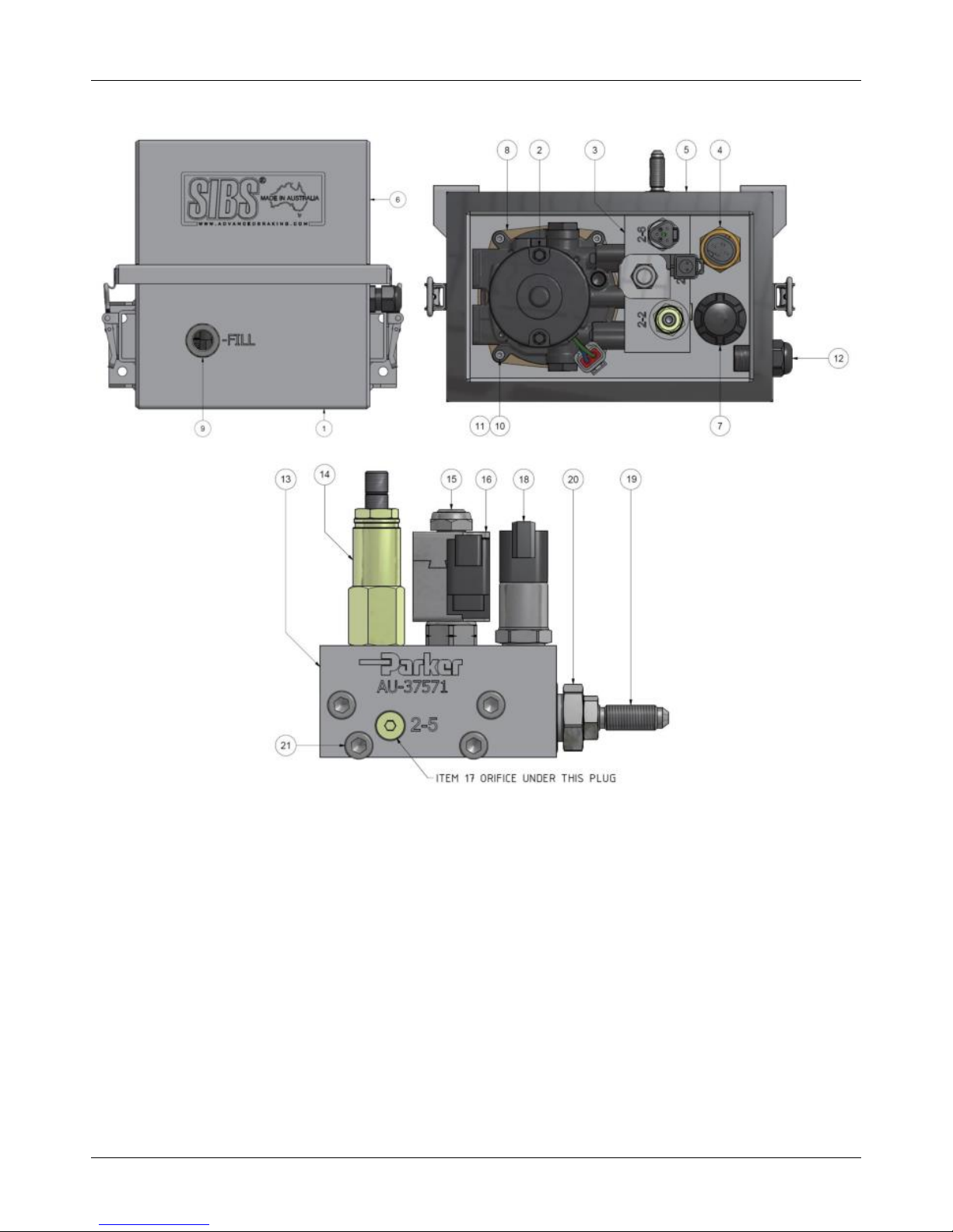
9. Pump Hardware Parts List 12V

MAN-059 8 FEB 2017
15
ITEM
PART NO.
DESCRIPTION
QTY/KIT
1
18-9015
ENCLOSURE BASE/RESERVOIR
1
2
18-9026
POWER UNIT 12V (PUMP + ADAPTER + MOTOR)
1
3
18-9014
MANIFOLD ASSEMBLY 12V
1
4
18-9027
LEVEL SENSOR
1
5
18-9028
ENCLOSURE GASKET
1
6
18-9028
ENCLOSURE LID
1
7
18-9024
FILL CAP
1
8
18-9029
POWER UNIT GASKET
1
9
18-9030
LEVEL WINDOW
1
10
18-9031
SCREW POWER UNIT
4
11
18-9032
WASHER SPRING POWER UNIT
4
12
18-9033
CABLE GLAND
1
13
18-9034
MANIFOLD BLOCK
1
14
18-9035
RELIEF VALVE
1
15
18-9036
SOLENOID VALVE
1
16
18-9021
COIL 12V
1
17
18-9037
ORIFICE 0.5mm
1
18
18-9017
PRESSURE SENSOR
1
19
18-9038
BULKHEAD FITTING
1
20
18-9039
ADAPTER FITTING MANIFOLD TO BULKHEAD
1
21
18-9040
SCREW MANIFOLD BLOCK
4
22
18-4033
MANIFOLD O-RING SEAL KIT
1

MAN-059 8 FEB 2017
16
10. Pump Hardware Parts List 24V

MAN-059 8 FEB 2017
17
ITEM
PART NO.
DESCRIPTION
QTY/KIT
1
18-9015
ENCLOSURE BASE/RESERVOIR
1
2
18-9044
POWER UNIT 24V (PUMP + ADAPTER + MOTOR)
1
3
18-9025
MANIFOLD ASSEMBLY 24V
1
4
18-9027
LEVEL SENSOR
1
5
18-9028
ENCLOSURE GASKET
1
6
18-9028
ENCLOSURE LID
1
7
18-9024
FILL CAP
1
8
18-9029
POWER UNIT GASKET
1
9
18-9030
LEVEL WINDOW
1
10
18-9031
SCREW POWER UNIT
4
11
18-9032
WASHER SPRING POWER UNIT
4
12
18-9033
CABLE GLAND
1
13
18-9034
MANIFOLD BLOCK
1
14
18-9035
RELIEF VALVE
1
15
18-9036
SOLENOID VALVE
1
16
18-9022
COIL 24V
1
17
18-9037
ORIFICE 0.5mm
1
18
18-9017
PRESSURE SENSOR
1
19
18-9038
BULKHEAD FITTING
1
20
18-9039
ADAPTER FITTING MANIFOLD TO BULKHEAD
1
21
18-9040
SCREW MANIFOLD BLOCK
4
22
18-4033
MANIFOLD O-RING SEAL KIT
1

MAN-059 8 FEB 2017
18
11. Installation –Driveline Brake (Light - Medium Trucks)
1. The SIBS® driveline brake is installed on the forward side of rear differential carrier.
2. Drain and keep enough diff oil from the rear differential carrier to prevent spillage as the pinion bearing cage will be
removed for SIBS® brake installation.
3. Remove drive shaft from rear yoke. The drive shaft may be removed completely if desired.
4. Remove the yoke from the pinion shaft.
5. Remove the pinion bearing cage and retain any shims for later use. Ensure no dirt ingress into the diff centre.
6. Remove and keep the bearing rollers. Remove and discard pinion seal.
7. The pinion bearing cage must be machined as per ABT drawing to suit the attachment of the SIBS® brake.
8. Attach the modified pinion bearing cage to the diff centre as per Canter manual. Ensure all shims are reused. Do not
attach any mounting bolts at this stage.
9. Attach the outer bearing roller and pull the pinion shaft forward to ensure it is positioned correctly.
10. Attach the pinion seal to the bearing cage.
11. Apply Loctite 515 between the bearing cage and the SIBS® inner brake housing. Note: in some cases a mounting adapter
is required between the bearing cage and the inner housing. If required apply Loctite 515 to both sides.
12. Attach the inner housing with the brake pads positioned to the top of the brake.
13. Attach the mounting bolts and washers. Torque to 100Nm. Repeat 3 times over 5 minutes.
14. Ensure the housing o-ring is attached to the outer brake housing.
15. Ensure the brake pads are in position on the inner brake housing.
Figure 1: Diff centre with inner housing attached.
16. Attach the V-seal to the yoke.
17. The preassembled outer housing should be attached to the yoke and rotor. Ensure brake pads are attached to the outer
housing.
Brake Pads
Mounting Bolts and washers
Pinion
Seal

MAN-059 8 FEB 2017
19
Figure 2: Outer housing, yoke and rotor assembly.
18. Attach the outer housing, yoke and rotor to the inner brake housing. Use of a jack or lifting table is recommended to
assist with lifting the assembly into position.
19. Hold the brake rotor to prevent it from detaching from the yoke during assembly.
20. Lift outer assembly and align the yoke with the pinion shaft with the EMMA spring covers positioned towards the bottom
of the brake.
21. Once the brake is held by the pinion shaft, rotate the outer housing until the EMMA spring covers are positioned towards
the top of the brake.
22. Remove any rotor retaining devices once the inner and outer housings are as close to each other as possible.
23. Align the dowel pins before attaching the housing bolts.
24. Fit the 12x M10 bolts and torque to 50Nm in sequence. Ensure each bolt is torqued twice.
25. Attach the 2x grease nipples to the yoke.
26. Attach the pinion shaft nut. Set preload and torque as per Fuso Canter Manual.
27. Ensure the diff rotates freely when the SIBS® brake is released.
Figure 3: Brake mounted in position on the forward side of the rear diff centre.
28. Assemble the drive shaft onto the ABT yoke. Torque fasteners to 130Nm.
29. Complete the hydraulic and electrical installations as per sections 10 and 11 of this manual.
30. Remove the 4 x retractor bolts from the brake and retain in the vehicle.
Ensure Brake Pads are in position
before attaching rotor (not shown)
EMMA Spring cover
EMMA Spring cover centred
at the top of the brake
M10 Housing bolts located
on the rear facing side

MAN-059 8 FEB 2017
20
31. Attach 3 x taper plugs to the spring covers. Use Loctite Silver Grade Anti-seize on the threads of the taper plugs to assist
with future removal. Torque to 10Nm.
32. Silicone may be used to fill the socket head of the taper plugs to prevent dirt ingress.
33. Attach 1 x pad wear indicator plunger to the EMMA piston inside the remaining hole in the spring cover. Torque to 15Nm.
34. Attach the pad wear indicator plug to the spring cover over the pad wear indicator plunger. Ensure it is threaded all the
way onto the spring cover. Torque to 15Nm.
35. Attach the fibre washer and cap. Torque to 10Nm.
Figure 4: SIBS Brake assembly attached to rear diff centre.
36. Mount the expansion chambers as high as possible in a protected location on the vehicle. ABT recommends mounting to
the chassis cross-member.
37. Secure using the supplied mounting hardware.
38. Run a length of breather hose between the expansion chamber and the brake unit.
39. Route the hose away from the exhaust and any moving components. Allow extra length for axle articulation.
40. Protect areas of the hose that may abrade using spiral guard.
41. Ensure SIBS® fluid can easily drain back into the brake units.
42. Secure the hose using supplied P-clips.
Figure 5: SIBS Brake assembly attached to rear diff centre.
Pad wear indicator location
Expansion Chamber
Breather hose fitting
On brake unit
Table of contents


