Sic Marking ec7 User manual

User Guide
ec7 – e7p62 – e7p122
SIC MARKING
13 route de Limonest
ZAC de la Braille
69380 LISSIEU – France
Telephone: (+33) 04.72.54.80.00
Fax: (+33) 04.78.47.39.40
E-Mail: [email protected]
http://www.sic-marking.com
NOTE7V1EC7P62P122US-R01.doc 1/46


CONTENTS
EQUIPMENT SUPPLIED FOR THE STANDARD SYSTEM ..........................................................................7
UNPACKING ......................................................................................................................................7
INSTALLATION ..................................................................................................................................7
a) Fixing.......................................................................................................................................7
b) Power supply ...........................................................................................................................7
II - USE ...............................................................................................................................................8
SAFETY .............................................................................................................................................8
HOW TO MARK ..................................................................................................................................8
a) Positioning and securing of the part to be marked..................................................................8
b) Regulating the stylet / part distance .......................................................................................9
c) Starting / stopping marking .....................................................................................................9
INTRODUCTION TO THE SOFTWARE..................................................................................................10
III - STARTING UP ........................................................................................................................12
THE OPENING SCREEN .....................................................................................................................12
MARKING MODE......................................................................................................................12
a) Description of the screen........................................................................................................12
b) Tab functions .........................................................................................................................12
INTRODUCTION........................................................................................................................13
c) Description of the screen .......................................................................................................13
FIRST MARKING FILE .......................................................................................................................13
d) Printing..................................................................................................................................13
e) Marking..................................................................................................................................14
SETTINGS IN WRITE MODE. .............................................................................................................14
IV - FILE MANAGEMENT ...........................................................................................................17
INTRODUCTION........................................................................................................................17
LOADING A FILE INTO MEMORY.......................................................................................................17
DELETING FILES ..............................................................................................................................17
V - ADVANCED FUNCTIONS ......................................................................................................18
USING THE ADJUSTMENT FUNCTION ........................................................................................18
USING THE GRAPHIC VIEW.......................................................................................................18
USING THE VARIABLE FIELDS ..........................................................................................................20
a) The time variables and special characters ............................................................................20
b) Increments..............................................................................................................................21
ENTRY OF A LOGO:..........................................................................................................................22
VI - CONFIGURATION .................................................................................................................23
CONFIGURING THE MACHINE...................................................................................................23
CONTROL HANDBOX ACCESSORY (4 300 379).................................................................................24
VII - MAINTENANCE....................................................................................................................25
INTRODUCTION ...............................................................................................................................25
AFTER SALES SERVICE....................................................................................................................25
NOTE7V1EC7P62P122US-R01.doc 3/46

PREVENTATIVE MAINTENANCE ........................................................................................................25
1ST LEVEL MALIGNANCE ..................................................................................................................26
.........................................................................................................................................27
VIII - ANNEXES..............................................................................................................................28
1 - PERCUTEURS GAMME E7 ............................................................................................................28
a) hammer mechanism ec7.........................................................................................................28
b) hammer mechanism ep7 ........................................................................................................30
2 - COLUMN MOUNTED MARKING MACHINE EC7..............................................................................32
3 - MARKING GUN E7P62 ................................................................................................................39
4 - MARKING GUN E7P122 ..............................................................................................................43
5 - E7 MONITOR..............................................................................................................................46
c) Electrical diagram for e7 monitor .........................................................................................46
NOTE7V1EC7P62P122US-R01.doc 4/46

INTRODUCTION
Thank you for choosing an SIC MARKING machine.
SIC MARKING systems help improve the traceability of your products as
required by industrial standards.
We would like to extend a warm welcome you to as one of the users of our
systems.
This guide contains installation instructions for our micro percussion series and
also instructions for use. We strongly advise that you read these instructions
carefully before starting to install the system.
Our technical advice team remains at your disposal for further information.
NOTE7V1EC7P62P122US-R01.doc 5/46


EQUIPMENT AND INSTALLATION
Equipment supplied for the standard system
The standard system is made up of -
• marking mechanism with integrated electronic controls
• power lead
• maintenance kit
Unpacking
Unless delivered by us, the marking equipment is delivered in its own packaging. This packaging
should be kept carefully in case the equipment needs to be returned under guarantee.
Carefully unpack the pre-packed sub-units
Installation
a) Fixing
o install the equipment on a rigid, stable surface
b) Power supply
o before connecting the marking machine to the power supply (230V or 115V) check
that it has been set to the right voltage; check the voltage marked on the fuse drawer
o if the voltage selected is not the right one -
remove the fuse drawer from the base of the power unit
switch over the power switch
change the fuses (2 AT at 230V and 4 AT at 115V)
put the unit together again
o Switch on the marking equipment using the On/Off (0/I)switch at the back of the unit.
o the SIC screen will appear after a few moments, the software will load and the
main menu window will appear. The monitor is now ready.
ALTHOUGH THE EQUIPMENT IS PROTECTED IN LINE
WITH CURRENT STANDARDS
THE ELECTRONICS MAY BE SENSITIVE TO EXTERNAL
INTERFERENCE
IT SHOULD BE INSTALLED USING A STANDARD CABLE
WARNING
AND PROTECTED FROM POSSIBLE RADIATION
NOTE7V1EC7P62P122US-R01.doc 7/46

II - USE
Safety
When used intensively the temperature of the hammer unit may
reach 100 °C
the wearing of goggles is recommended
the wearing of helmet mounted ear defenders os also recommended
sound level of the machine when marking:
76 dB* on a steel block at an average impact and speed
(* Warning, this is not an upper limit the noise will depend on the
ob
j
ect to be marked
)
When using the marking system never hammer into an empty space
the tip may shatter
How to mark
a) Positioning and securing of the part to be marked
Although during marking the part will not be subject to much force it will be necessary to
immobilize it in order to achieve the best quality marking.
Depending on the nature of the part and the working conditions, this may vary from simple
manual holding in place against a right angle (angle bar) to mechanical, magnetic or
pneumatic securing.
If a marking gun is used, place the anti-skid universal support against the surface to be
marked and hold the gun manually in position during marking.
The holding system should position the part in such a way that the plane in which the stylet
operates should be parallel with the surface to be marked.
For portable machines, if the marking is always on the same type of part, we would advise
that a guide plate be machined so as to be able to guarantee the marking position.
NOTE7V1EC7P62P122US-R01.doc 8/46

b) Regulating the stylet / part distance
The quality of the marking depends in large measure on the part to be marked (materials,
state of the surface, hardness etc.).
A smooth, flat surface will be much easier to mark than a granulated irregular surface.
Usually it will be necessary to adapt the force used in the marking to the height of the
characters. The smaller the letters the less impact there will need to be to make them
legible. It is also possible to select more or less close marking with the help of the software
matrix.
Good quality marking can be obtained by adjusting the impact of the marking and the
stylet / part distance. If using a marking gun the stylet / part distance can regulated by
adjusting the position of the supporting surface
As a guide below are the recommended distances between the stylet and the part taking
into account the marking impact chosen.
Impact 1 2 3 4 5 6 7 8 9
Minimum distance 0.5 0.5 0.5 1 1 2 3 5 6
Maximum distance 1 2 3 5 6 7 9 9 9
Maximum distance stylet / part 9 mm
It would be wise therefore, to undertake preliminary tests on any new parts.
c) Starting / stopping marking
o set the monitor to marking (for more information see the software manual)
o put the part to be marked into position
o start the marking by pressing on the 'start' button or on the 'on/off' button on the handle
of the gun (portable machine)
o to stop the marking, press on the 'stop' button or for more than two seconds on the
'on/off' button of the gun.
NOTE7V1EC7P62P122US-R01.doc 9/46

Introduction to the software
- Special keys
The F1 to F9 ( …) keys are generally keyboard shortcuts.
The key cancels data input in progress or returns you to the previous window
The key enables you to validate data entry or move on to on to the next field.
The key enables you to return to the previous field, to validate the data in the
present field and to return to the previous field
The and keys enable you to scroll through a list
Combining the + keys enables you to go to the end of the data field
Combining the + keys enables you to return to the start of the data field
In write mode the keys enable you move from one line to another.
- The data fields
In the active field (here zone X) the field is in reverse- video and a cursor is blinking at the
insertion point.
- The fields list
S
p
ee
d
NOTE7V1EC7P62P122US-R01.doc 10/46

The fields followed by arrows: (as for the Speed field) are list type fields:
- the and arrows enable you to scroll through this list
- the key enables you to show the contents of the list:
- another key starts a search from the first letter of the list
- Data entry using insert mode
By pressing on the key the cursor moves from being a hyphen to a
square this means that you have moved form insert mode to over-write
mode.
Those fields that are longer than the screen display are displayed as follows:
NOTE7V1EC7P62P122US-R01.doc 11/46
III - STARTING UP
The opening screen
V
1-0-0
(2004-01-26)
V1-0-0 : Programme version number,
(2004 –01-26) : programme creation date (Year, Month, Day)
After initialisation the monitor moves into marking mode.
Marking Mode
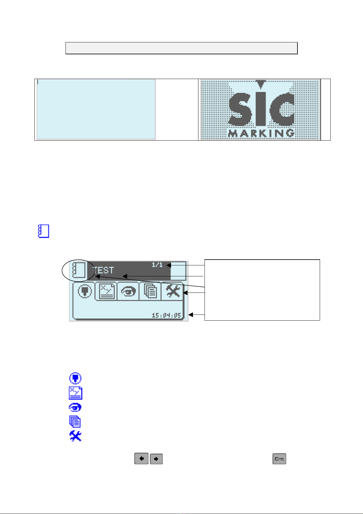
a) Description of the screen
N
umber of lines in the file
N
ame of the active file
Mode in use indicator
Selector tab
Time
b) Tab functions
The main screen is the software's point of entry.
Marking mode.
Write mode of the marking file.
Graphic representation of the marking file
File management.
Configuring the machine.
Tab selection: use the keys to select a tab then press on the key to see the
menu.
NOTE7V1EC7P62P122US-R01.doc 12/46

Introduction
c) Description of the screen
From marking mode open the tab to go into write mode.
This mode enables you to create a marking file
Write icon
Toolbar
Configuration values
First marking file
d) Printing
As an example we will create a new file
Press the key to create a new file
The monitor screen should be as follows
The X and Y fields represent the marking coordinates
(Y is aligned on the base of the characters)
Let us create a line where the word TEST will be engraved
where X=5 and Y=5 and size is 3 by 3 mm
Press then 5 5
Then press then 3 3
Finally select then [T] [E] [S] [T]
Finally, save the file
NOTE7V1EC7P62P122US-R01.doc 13/46
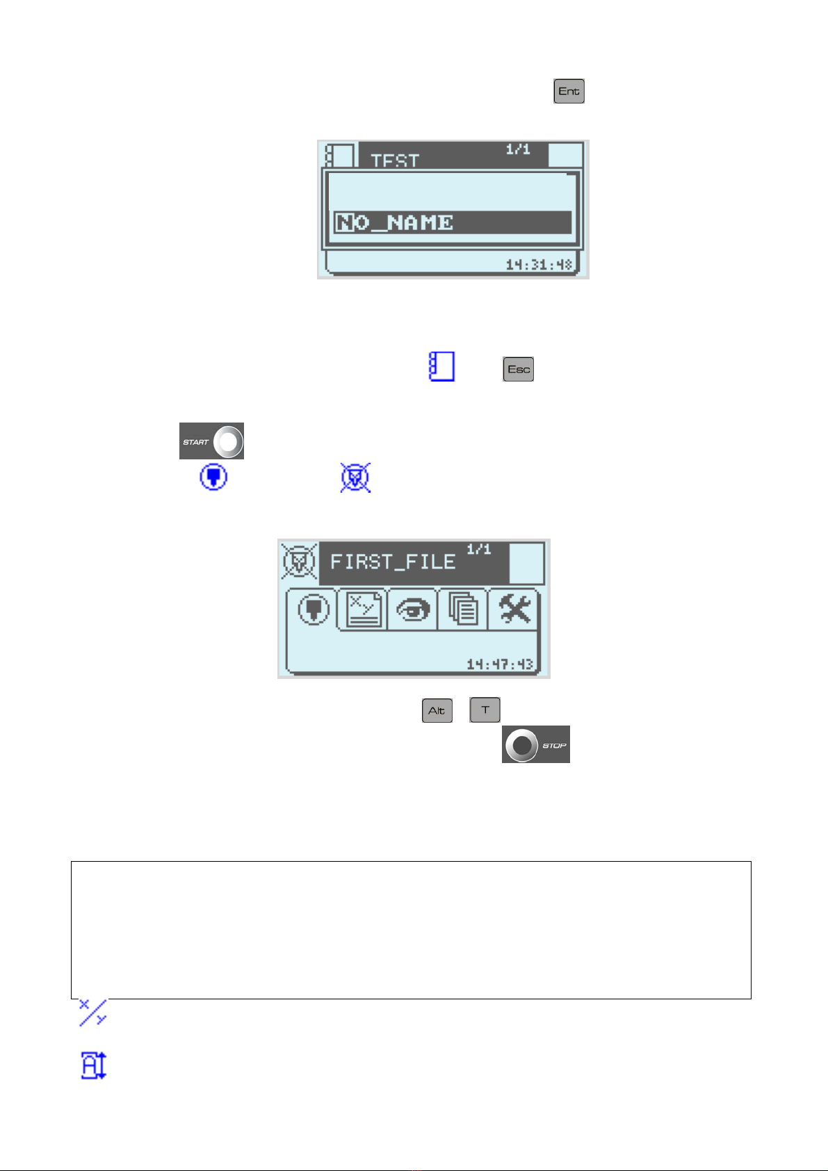
Name it, for instance, FIRST FILE then validate it using .
Save as
e) Marking
To leave write mode and enter marking mode , press .
- One press on will start the marking
- Opening the tab then clicking on allows you can simulate the marking cycle (moves the
marking head but there is no power to the stylet)
At the end of the marking cycle (or the simulation) + will give you the marking time.
It is possible to interrupt the marking underway by pressing on .
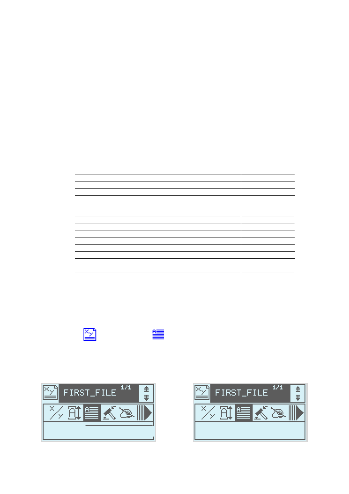
Settings in write mode.
Function keys in write mode
F2………..Delete line in progress.
F3………..Load a file.
F5………..Insert Line.
F7………..Graphic View.
F8………..Adjustment.
F9……….New marking file.
The X and Y fields represent the marking coordinates (Y is aligned on the base of the
characters)
The Land Hfields represent the width and height of the characters.
NOTE7V1EC7P62P122US-R01.doc 14/46

Text to be marked.
The Depth field represents the force of the impact: Impact 1is weak, Impact 9is strong
Impact 0does not mark
The Quality field represents point size Smp = character on a 5x7 grid
Dbl = character on a 9x13 grid
0.58 = 0.58 mm between each point
Font style of character OCR, OCRA, ARIAL, COURIER
The Speed field allows you to regulate the speed of movement of the slotted table during
marking
1= Slow speed, 2= intermediate speed, 3 = fast speed
Angled marking
Radial marking
The X and Y fields represent the centre of the circle (and not the co-ordinates of the first letter)
The angle represents the starting angle of the trace
Adjustment mode
Some examples
•Straight marking
ANGLE RADIUS
original position
Y
X
•angled marking
ANGLE RADIUS
X
Y
ANGL
original position
NOTE7V1EC7P62P122US-R01.doc 15/46

•Circular marking
ANGLE RADIUS
X
Y
ANGL
RADIUS
original position
NOTE7V1EC7P62P122US-R01.doc 16/46

IV - FILE MANAGEMENT
Introduction
Open the file management tab .
The monitor screen should be as follows
Search area
File list
Memory in use
FIRST
_
FILE
2%
Loading a file into memory
select a file using the , , and arrows.
You can search for a file by starting to type in its name in the search area (the key removes
what you have typed)
Deleting files
Selection of files is the same as for opening files
Once selected the file can be deleted using the key
Delete
FIRST_FILE
Yes(y) No(n)
to confirm deletion press (y)es
NOTE7V1EC7P62P122US-R01.doc 17/46
V - ADVANCED FUNCTIONS
Using the adjustment function
To help the operator in adjusting the marking files, the ADJUSTMENT function allows
you to position the marking head with the marking co-ordinates.
This function is available from write mode or by using F8
The screen is then as follows
Setting the X, Y co-ordinates by adjusting the marking head
use the (+) and arrows (-) keys to set the adjustment.
use the keys to move the stylet one step in the
corresponding direction
the key allows you to simulate marking.
the keys allows you to draw the marking outline.
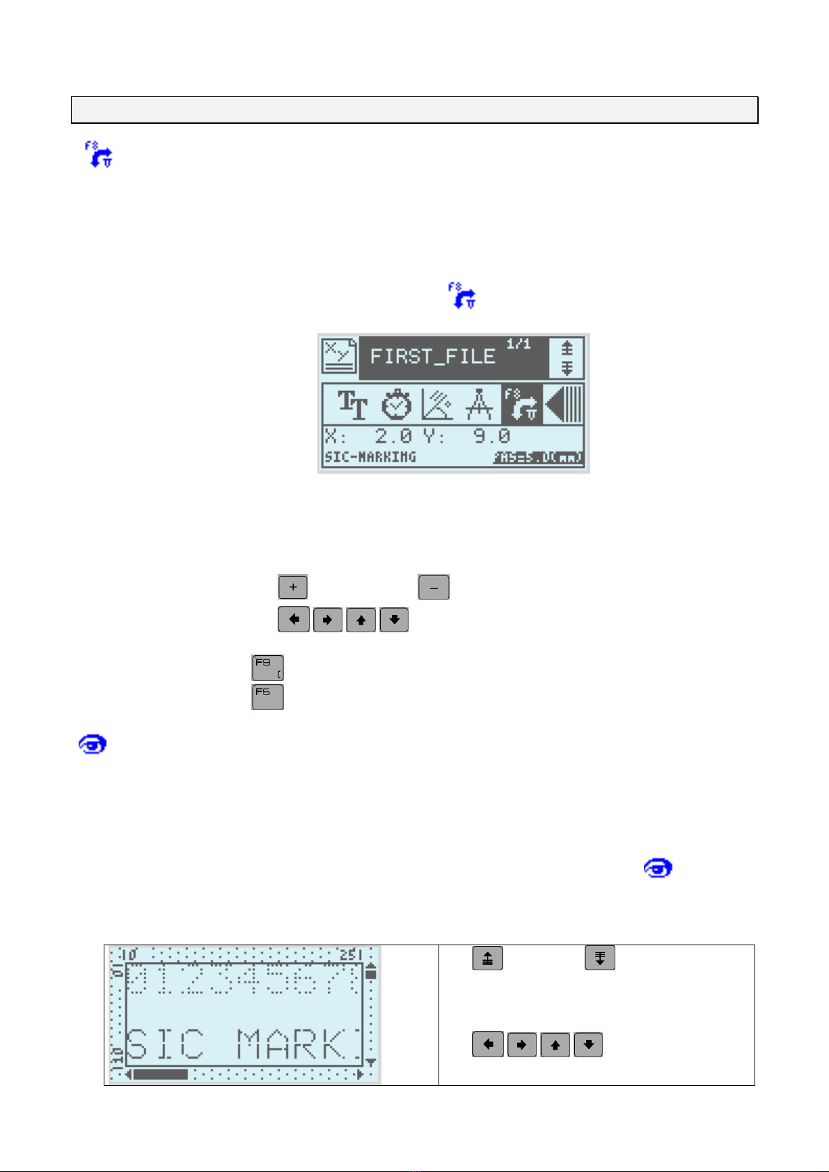
Using the graphic view
The graphic view function enables the operator to pre-view the marking on the
machine's screen.
This function can be accessed from write mode, from F7 or form the tab from
marking mode.
The screen is then as follows
the and arrows allow you to
regulate the zoom.
the keys allow you to
move the window
NOTE7V1EC7P62P122US-R01.doc 18/46

NOTE7V1EC7P62P122US-R01.doc 19/46
Using the variable fields
When one part of the text to be marked regularly needs modifications, such as increments
using a counter or date stamping, it is advisable to use the variable functions rather than
completely re-enter the data every time (and thereby increase the possibility of errors at each
change)
There are two function types; time variables and increments.
The increments are attached to a single file
The time variables are common to all files.
a) The time variables and special characters
•introduction
The time variables are: code
The current year; 3 formats are available
4 numbers eg. 2004 #Y4
2 figures eg 04 #Y2
1 figure eg 4#Y1
The current month; 1 format is available
2 figures eg 12 for December #M
The week in progress , One format available #W
The current day; 3 formats are available #D3
A part of the year (from 1 to 366) #D2
The day of the month using 2 figures (from 1 to 31) #D1
The day of the week (0=Sunday, 6=Saturday)
Time 2 formats are available #h
The hours using 2 figures #m
Minutes using 2 figures
Configuration of times
From write mode select the text icon
Instead of entering text from the keyboard press Alt-H
Then select the variable timing format from the list.
After validation
Text : #Y4
#
Y4
V
AR. H.
NOTE7V1EC7P62P122US-R01.doc 20/46
This manual suits for next models
2
Table of contents
Other Sic Marking Industrial Equipment manuals


