Sices DST4602 User manual

DST4602 Remote
User’s Manual
Filename: EAAM048702EN.DOCX
Rev. 02 Date: 06/05/2015
ID Document: EAAM0487
Product: DST4602 Remote
ii DST4602Remote User’s Manual
Revision
Dat
e
Page
s
Note
00 16/12/2014 13 First version of the manual, released for the version
01.00 of the controller.
01 20/02/2015 13 Upgrade to version 00.49 of the controller.
Summary added.
3, 5.8
02 06/05/2015 13 Correction in paragraph 5.6.

DST4602Remote User’s Manual iii
INDEX
1. Introduction..............................................................................................................3
2. Views of the device..................................................................................................4
2.1 Installation................................................................................................................5
3. Connection...............................................................................................................5
3.1 Supply.......................................................................................................................5
3.2 Digital output............................................................................................................6
3.3 Connection to DST4602 via Ethernet.....................................................................6
3.4 Connection to DST4602 via RS-485 .......................................................................8
3.4.1 Connection to the DST4602 J14 port................................................................9
3.4.2 Connection to the DST4602 J16 port................................................................9
4. Information displayed on Remote........................................................................11
5. Commands and settings.......................................................................................11
5.1 Silencing the acoustic horn..................................................................................11
5.2 Faults acknowledgement......................................................................................11
5.3 Alarms reset...........................................................................................................12
5.4 Genset start............................................................................................................12
5.5 Genset stop............................................................................................................12
5.6 Take/release the load ............................................................................................12
5.7 MCB Button............................................................................................................13
5.8 Remote parameters configuration .......................................................................13
DOF.0001.........................................................................11
DOF.0002.........................................................................11
P.0101...........................................................................6; 8
P.0102...........................................................................6; 8
P.0103...........................................................................7; 8
P.0104...........................................................................7; 8
P.0105...........................................................................7; 8
P.0106...........................................................................7; 8
P.0201....................................................................... 6; 7; 8
P.0202...........................................................................7; 8
P.0301..................................................................6; 7; 9; 10
P.0302...................................................................... 7; 9; 10
P.0303...................................................................... 7; 9; 10
P.0304.................................................................7; 9; 10; 11
P.0305..............................................................................12
P.0331............................................................................7; 8
P.0332............................................................................7; 8
P.0361..........................................................................9; 10
P.0362..........................................................................9; 10
P.3000................................................................................6
P.3001..........................................................................6; 11


DST4602Remote User’s Manual 3
1. Introduction
This document describes the “DST4602 Remote” controller (hereinafter Remote). The
controller works as a remote displayer of data and measures of another “DST4602” or
“DST4602 Evolution” (hereinafter DST4602).
In particular, this document indicates:
How to wire and configure the Remote controller.
How to configure the DST4602 controller to which it is connected.
Which information are displayed on the Remote controller and which commands are
available.
Remote can be connected to DST4602 controllers only, with a software equal to or superior
than 00.47. The first version of the Remote software is indeed 00.47, as the DST4602 one. It
is important that both Remote and related DST4602 controllers have the same software
revision.
The Remote controller code is E610217560000.
The Remote controller software code is: EB025024600xx.

4 DST4602Remote User’s Manual
2. Views of the device
Front view
Rear view
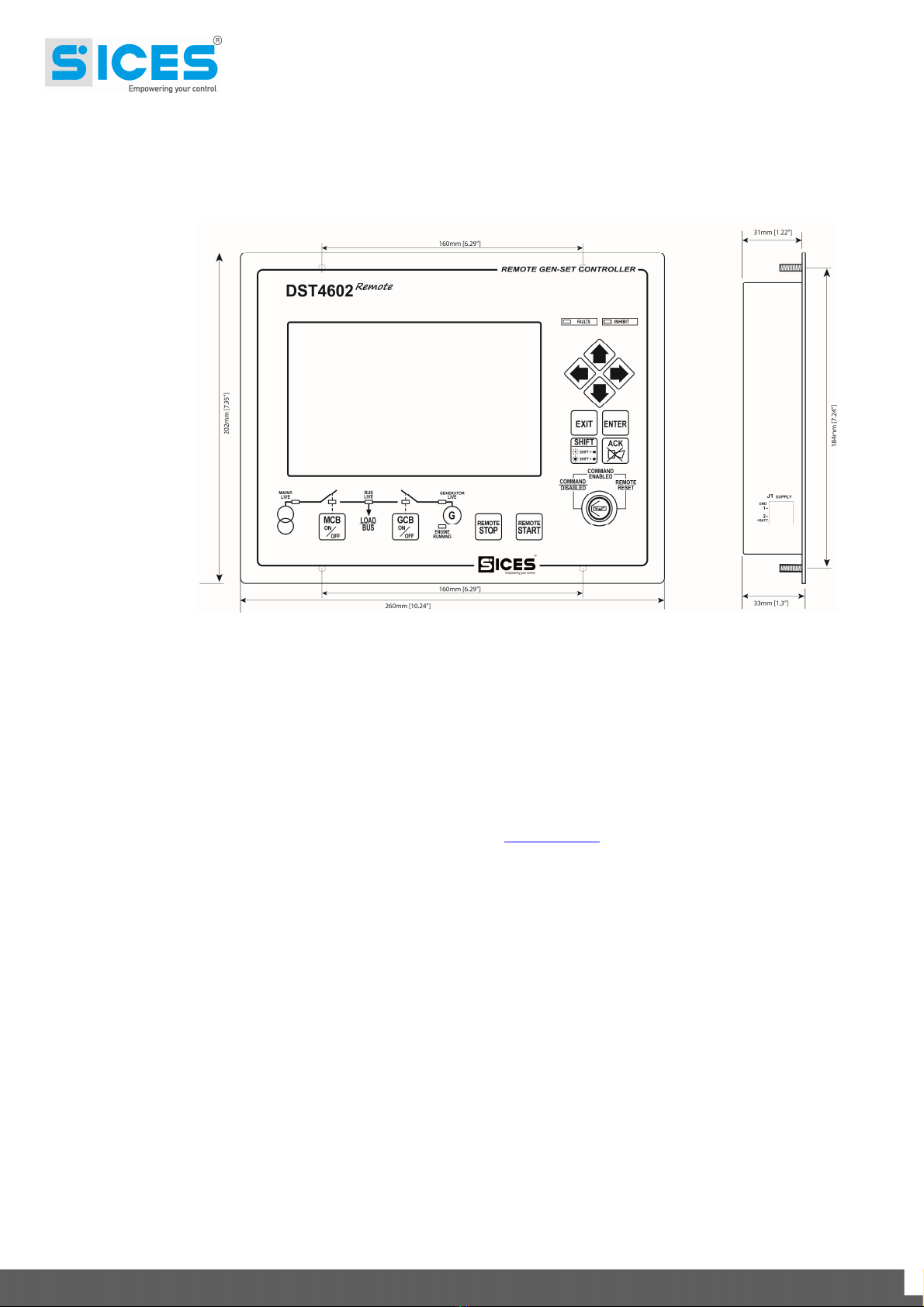
DST4602Remote User’s Manual 5
2.1 Installation
Dimensions and holes for the assembling
3. Connection
Remote can be connected to DST4602 via Ethernet or RS-485. Both connections are
described in the following paragraphs.
There is also a description of the parameters that need to be set on Remote in order to
configure it correctly. The parameters can be set using the USB port on the controller (J6
connector): the two dip-switches (SW1) near the J6 connector must be on “OFF”. Starting from
the revision 00.49,the parameterscan be modified directly by the Remote panel (see par.5.8).
To configure the parameters, it is necessary to have the software BoardPrg3, produced by
SICES and in free download on our website (www.sices.eu). Once the software is installed on
a PC, you just need to connect a USB cable between the PC and the J6 connector: Remote
will be visible on the PC as an additional serial port (in case of problems, you can download
for free also the USB port driver for Windows).
The communication protocol used for the USB connection is Modbus-RTU: the Remote
Modbus address is “255”.
It is possible to use also the Ethernet connection to configure the controller: in this case, it is
necessary to know the Remote IP address first. Using the Ethernet connection, the protocol
used is Modbus-TCP: the Remote address is “255” too.
3.1 Supply
Remote has to be supplied between 8 and 33 Vdc, by the genset start battery voltage (as the
DST4602 controller) or a different power supply. Note: the battery voltage displayed on
Remote is the one of the Genset, Remote does not measure its own supply source.
J1 connector is the supply connector: connect the voltage to the terminal “1-GND” (negative)
and to the terminal “2-+BATT” (positive).

6 DST4602Remote User’s Manual
3.2 Digital output
Remote provides one relay digital output (1Ampere @30Vdc) completely configurable. The
J4 connector provides dry contacts in place of the relay:
1. Common terminal.
2. Terminal usually open.
3. Terminal usually closed.
A function cab be combined to the configurable output by means of the parameter P.3001.
The functions available are:
DOF_0000: the output is not used (standby).
DOF_0001: the outputis used forthecommand of an external horn. Remote activates
the output together with the internal horn.
DOF_0002: the output indicates the communication with DST4602. The output works
if there is communication and fails if the communication stops.
Note: bymeansof P.3000it ispossible to invert thepolarity of the output (invertingthe contacts
NO and NC).
3.3 Connection to DST4602 via Ethernet
The Remote Ethernet port is available on the J5 connector.
In order to enable the connection to DST4602 via ETHERNET it is necessary to set the
parameter P.0301 to "0".
The connection can be carried out in two ways:
By a point-to-point connection between the controllers (one Ethernet cable connected
to the Remote and DST4602 Ethernet ports).
By connecting Remote and DST4602 to an Ethernet existing line (using HUB or
switches).
Anyhow, it is important to correctly configure the Ethernet line on Remote.
In order to make Remote and DST4602 communicate, it is necessary to configure the
following four parameters:
Set the “Subnet mask”. This configuration can only be carried out by P.0101 on
Remote and by P.0501 on DST4602. Usually, it is used the value “255.255.255.0”
(that is the preset factory value). If the two controllers are connected to the same
subnet, set the same value on both controllers.
If the two controllers are connected to two different subnets, it’s important to set (for
each one) the “Gateway” IP address of the related subnet. It is usually a server or a
switch with an own IP address and which exchange messages among subnets. Use
the parameter P.0102 on Remote and P.0502 on DST4602 to set the Gateway IP
address.
Another important parameter for the communication via Ethernet is the IP address.
The Remote and DST4602 controllers have two different IP addresses. If the two
controllers are connected to the same subnet, the part corresponding to the value
“255” must be the same, while the other part must be different. The IP address can be
configured with the parameter P.0201 on Remote andwith P.0500 onDST4602. After
having configured both IP addresses correctly, indicate to Remote which IP address

DST4602Remote User’s Manual 7
has been configured on DST4602: to this purpose use P.0331 (which has to be set to
the same value of P.0500 on DST4602).
The last important parameter for the Ethernet communication is the TCP port used for
the Modbus communication. The default value is “502” and can’t be changed, unless
it is strictly necessary. Use P.0202 on Remote and P.0503 on DST4602. After having
configured the TCP ports correctly, indicate to Remote which TCP port has been
configured on DST4602: to this purpose use P.0332 (which has to be set to the same
value of P.0503 on DST4602).
Remote supports the DHCP protocol, that is the automatic assignment of the IP address by
network server (function soon available on DST4602). By means of this function, just one
name must be assigned to Remote, and the DHCP server will combine an IP address to that
name. To use this function, you need to:
Set the name chosen for Remote in P.0201 (instead of the IP address).
Set the IP address of the network server that offers the DHCP service in P.0103. If
you don’t’ know the server IP address, you can try to set the parameter P.0103 to
“255.255.255.255”: Remote will automatically try to contact the proper server.
Set the portfor theDHCP service.This port isstandard (67) and shouldn’t bechanged.
It can be set using the parameter P.0104.
The function is disabled if the parameter P.0103 or P.0104 are at zero. Once set, Remote will
contact the DHCP server providing its name, and the DHCP server will send the information
back, including the IP address assigned to Remote and to the subnet mask to use.
The data sent back to the DHCP server are displayed on Remote when it is not connecting to
DSt4602.
When DST4602 will support the DHCP function, it won’t be possible to set on Remote the
DST4602 IP address (as it is assigned dynamically by the server): in its place, you must set
the univocal DST4602 name (always using the parameter P.0331). Then Remote will contact
the DNS server to get the IP address that corresponds to the name of DST4602. If the DHCP
server is enabled on Remote, the DHCP server already provides to Remote the IP address of
the DNS server; if it isn’t enabled, it’s necessary to indicate the IP address of the DNS server
using the parameters P.0105 and P.0106.
The following table indicates the parameters to set for the Ethernet connection with DST4602:
Parameter Value
P.0301 0-Ethernet
P.0302 1
P.0303 Set to the same value of P.0505 on DST4602.
P.0304 Set to the same value of P.0004 on DST4602. Note: if the two parameters
are different, almost all Remote commands will have no effects on
DST4602.

8 DST4602Remote User’s Manual
P.0331 Set to the same value of P.0500 on DST4602. When DST4602 will support
the DHCP protocol, set it to the same value of P.0456 on DST4602
(univocal name of the network device).
P.0332 Set to the same value of P.0503 on DST4602. When it is possible, set both
parameters to “502”.
P.0101 Set the Subnet mask connected to Remote. The default value is
“255.255.255.0”, ask the network admin in case of doubt.
P.0102 This parameter has to be set only if DST4602 is connected to a different
subnet than Remote. Ask the network admin for the IP address of the
subnet Gateway connected to Remote.
P.0201
Set the IP address on the Remote controller. Ask the network admin for the
IP address of the subnet Gateway connected to Remote. If the subnet
supports the DHCP protocol, then set the univocal name of Remote (ask
the network admin in case of doubt).
P.0202 502.
P.0103
If the subnet connected to Remote supports the DHCP protocol (automatic
assignation of the IP address), set the IP address of the DHCP server or
“255.255.255.255” to let Remote individuate the server. In case you don’t
want to use the DHCP function, set to “0.0.0.0”.
P.0104 Set to 67, unless the DHCP server is using a non-standard port (ask the
network admin).
P.0105 Currently not used. Set the IP address of the primary DNS server when
DST4602 will supporter the DHCP protocol too. Note: if Remote uses
DHCP, the DNS server address has been already set automatically using
the DHCP protocol.
P.0106 Currently not used. Set the IP address of the secondary DNS server when
DST4602 will supporter the DHCP protocol too. Note: if Remote uses
DHCP, the DNS server address has been already set automatically using
the DHCP protocol.
3.4 Connection to DST4602 via RS-485
The Remote controller is equipped with an insulated serial port with RS-485 interface,
available on the J3 connector. This connector has 4 terminals.
Terminals 1 and 2 (internally connected in between): connect signal B (-) of RS-485.
Terminals 3 and 4 (internally connected in between): connect signal A (+) of RS-485.
The line RS-485 must have a 120 Ohm resistance on the two terminals. On Remote there is
a lever selector S1, that allow to insert/remove an internal 120 Ohm resistance on the line.
Usually, the selector S1 must be in ON.
It is possible to connect to both serial ports on DST4602.

DST4602Remote User’s Manual 9
3.4.1 Connection to the DST4602 J14 port
The connector J14 on DST4602 provides an insulated RS-485 serial port. The connection will
be as follows:
Near to the connector J14 on DST4602 there are two lever selectors called S4 and S5: set
them as per above image.
The table below summarizes the parameters to configure for the RS-485 connection with the
connector J14 on DST4602:
Parameter Value
P.0301 1 - RS-485
P.0302 Set to the same value of P.0472 on DST4602.
P.0303 Set to the same value of P.0475 on DST4602.
P.0304 Set to the same value of P.0004 on DST4602. Note: if the two parameters
are different, almost all commands on Remote will have no effects on
DST4602.
P.0361 Set to the same value of P.0473 on DST4602. We suggest the value
115200 (for both parameters).
P.0362 Set to the same value of P.0474 on DST4602.
3.4.2 Connection to the DST4602 J16 port
The connector J16 on DST4602 provides a non-insulated RS-232 serial port. In order to
connect, you need to use a RS-232RS-485 converter, produced by Sices:
Version 12 Vdc: E610202170002.
Version 24 Vdc: E610202170102.
RS-232 RS-485 Converter
male/female 9-pin serial cable

10 DST4602Remote User’s Manual
On the RS-232RS-485 converter, there is graft jumper called J100. By inserting it, the
internal 120 Ohm resistance is connected to the RS-485 line.
The table below summarizes the parameters to configure for the RS-485 with the connector
J16 on DST4602:
Parameter Value
P.0301 1 - RS-485
P.0302 Set to the same value of P.0452 on DST4602.
P.0303 Set to the same value of P.0470 on DST4602.
P.0304 Set to the same value of P.0004 on DST4602. Note: if the two parameters
are different, almost all commands on Remote will have no effects on
DST4602.
P.0361 Set to the same value of P.0453 on DST4602. We suggest the value 115200
(for both parameters).
P.0362 Set to the same value of P.0454 on DST4602.

DST4602Remote User’s Manual 11
4. Information displayed on Remote
The front panel of Remote duplicates every details of the DST4602 controller to which it is
connected. The different pages on the display are the same of those displayed on a DST4602
Evolution, even if Remote is connected to a DST4602 standard.
The led lamps on Remote duplicate those on the DST4602 connected.
Remote continuously asks DST4602 (by means of the serial port or Ethernet). If it doesn’t
receive answers for 5 seconds (or if the Ethernet cable is disconnected), it considers to be
disconnected to DST4602 (as when it has just been connected, until it receives answers).
When Remote considers to be disconnect to DST4602, it reacts as follows:
The relay output goes in standby (if it is configured with the function DOF.0002 -
parameter P.3001).
It display an error message on the graphic display. In this phase, the display shows
all the connecting parameters, to simplify the acknowledgement.
All the led lamps are off, except for the “FAULTS” led, which flashes.
When it gets the first answer from DST4602, Remote immediately activates the relay output
(if it is configured with the function DOF.0002 – parameter P.3001), so it starts upgrading the
display and the led lamps, duplicating the DST4602 controller screens (when Remote starts,
there is a delay of a few seconds before the visualization of the screens, because Remote
has to ask DST4602 for the complete status, and then only the necessary info).
On Remote, it is possible to select a language at page S.03. It can also be different from the
one selected on DST4602. Page S.03 can be displayed only if the communication with
DST4602 is live. The page displayed on Remote is independent from the one displayed on
DST4602: the two controllers can display two different pages.
5. Commands and settings
Note:many commandsdescribedbeloware not provided onDST4602 if the parameter P.0304
on Remote and P.0004 on DST4602 are set to different values.
Remote allows to set parameters and set points, reset counters, control the fuel pump, etc.
directly from the display pages, exactly ason DST4602.The only requisite to accomplish these
actions is that the key selector on Remote is on “COMMAND ENABLED”.
Using the push buttons on Remote it is possible to send commands to DST4602.
5.1 Silencing the acoustic horn
You can silence the acoustic horn on Remote by pressing the “ACK” button (in this way you
can silence the external acoustic horn too,if it has been configured with thefunction DOF.0001
in the parameter P.3001). Remote sends the silencing command to the DST4602 controller
too.
5.2 Faults acknowledgement
When pressing the “ACK” button while the horn is off (and while the key selector is on
“COMMAND ENABLED”), Remote sends an acknowledgement command of the faults on
DST4602. The faults stop flashing on the display, so the warnings are reset.

12 DST4602Remote User’s Manual
5.3 Alarms reset
On Remote, with key selector on “REMOTE RESET”, the controller sends an alarm reset
command to DST4602. Note: the command is sent at the switch: by leaving the “REMOTE
RESET” selector, just one alarm reset command is sent.
5.4 Genset start
Pressing “REMOTE START” on Remote, a remote start command is sent to DST4602. The
command is sent only if the key selector on Remote is on “COMMAND ENABLED”. DST4602
accepts the command only if it is on AUTO and if there aren’t requests of automatic
interventions (for example, in case of emergency plants, it accepts the command only if the
mains is live). Note: if DST4602 accepts this command, it will start the engine and all the
automatic operations to take the load (closure with or without synchronisation, power
management, etc.). In case you want to start the engine without taking the load, press the
buttons “SHIFT” + “REMOTE START” instead of “REMOTE START” only.
Note: if Remote loses the communication with DST4602 after sending the command,
DST4602 remains on “REMOTE START”.
5.5 Genset stop
Pressing “REMOTE STOP” on Remote, you can stop the genset. The stop command is sent
only if the key selector on Remote is on “COMMAND ENABLED”. DST4602 accepts the
command only if it is on AUTO. When pressing “REMOTE STOP”, if Remote had sent the
“Remote Start” command, it simply sends the opposite command and the engine will stop
without alarms, maybe carrying out the cooling cycle (the load will be automatically released).
Pressing “REMOTE STOP” without having pressed “REMOTE START”, DST4602 works as if
the “STOP” button had been pressed on its panel, that is activating the block “A007 –
AUTOMATIC MANUAL STOP”: theload will be released without power unload and the engine
will be stopped without cooling cycle.
Note: by pressing “REMOTE STOP” with the key selector on “REMOTE RESET” the test of all
the led lamps is carried out.
5.6 Take/release the load
Pressing “GCB”, Remote sends to DST4602 the proper command of activation/deactivation
of the “selector inhibition” function (according to the current status of the GCB). The command
is sent only if the key selector on Remote is on “COMMAND ENABLED”. DST4602 accepts
the command only if it is on AUTO.
Starting from version 00.55, bit 0 of parameter P.0305 selects the conditions in which “GCB”
Remote can accept the button “GCB”:
Bit 0 of P.0385 = 0. Remote accepts the “GCB” button only if previously it has send
the start commandforthe genset, and so only whenDST4602is in “REMOTE START”
mode.
Bit 0 of P.0385 = 1. Remote accepts the “GCB” button in any conditions, even if
DST4602 has started the genset by its own.
Commanding the GCB opening, DST4602 will automatically provide the possible power
unload before opening the circuit breaker. Commanding the GCB closing, the controller will
automatically activate the possible synchronisation and sharing of the load.
Note: for safety reasons, the “selector inhibition” command by serial port has a duration of 30
seconds on DST4602. Pressing “GCB” on Remote to force the opening of GCB, Remote

DST4602Remote User’s Manual 13
automatically confirms the command each 10 seconds. If the communication fails, after max.
30 seconds DST4602 cancels the inhibition and take the load again.
5.7 MCB Button
The MCB button is not used on Remote.
5.8 Remote parameters configuration
Starting from version 00.49, it is possible to configure the parameters on Remote directly on
its panel. In order to change these parameters, it is necessary to keep SHIFT pressed for five
seconds: then the controller shows the writing “Program function”.
Note: when you activate the mode for the parameters change on Remote, all the writings are
showed in red, in order to let the operator realize that he/she is modifying the parameters of
the Remote controller, not of the DST4602 controller by Remote.
The parameters change procedure is the same of the one for DST4602.
On the page where “Program function” is showed, you need to pressENTER to enter the main
menu of programming:
Select a submenu using the up/down arrows.
Press ENTER to enter the selected submenu.
Press EXIT to go back to the main menu (pressing EXIT on the main menu you exit
this mode and the display shows DST4602 data – if connected).
When entering a menu that contains only parameters (not other submenus), you can select
the desired parameter by using the up/down arrows. Note: the parameter value is showed in
yellow.
Pressing the ENTER button, you activate the change of the value of the highlighted parameter
(the square brackets will flash around the value to change):
Using the up/down arrows, you increase/decrease the value of the parameter or
character indicated. By pressing them together with SHIFT, the value can be changed
faster.
Using the left/right arrows, you move the indicator (only for some parameters).
Using the ENTER button, you save the new value.
Using the EXIT button, you cancel the change and restore the previous value of the
parameter.
See the document EAAM0485nnXA for the list of the parameters available.


SSSTTTTTGHTY
1
S.I.C.E.S. SRL
Società Italiana Costruzioni Elettriche Sumirago
Via Molinello 8B
21040 - Jerago con Orago (VA) ITALY
T +39 0331 212941
F +39 0331 216102
www.sices.eu
SICES BRASIL LTDA
Avenida Portugal, 1174
Condomínio Empresarial ONIX
06696-060 / ITAPEVI (SP)
T +55 11 4193 2008
www.sicesbrasil.com.br
contato@sicesbrasil.com.br
This document is owned by SICES s.r.l.. All rights reserved.
SICES s.r.l. reserves the right to modify this document without prior notice.
SICES has made any effort to ensure that the information herein provide are correct; in any case
SICES does not assume any liability for the use these information.
The disclosure by any means of this document to third parties is not allowed.
Other manuals for DST4602
2
Table of contents
Other Sices Remote Control manuals

Popular Remote Control manuals by other brands


Viessmann
Viessmann VITOTROL 200-E operating instructions

FUTABA
FUTABA 3GR-2.4GHZ instruction manual

Hitachi
Hitachi airPoint Room 700 Operation manual

Universal Remote Control
Universal Remote Control UR4U-MDVR2 operating instructions

Marmitek
Marmitek HR10 Specification sheet

Sony
Sony RM-V201 operating instructions