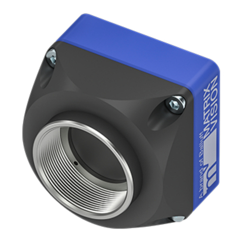
Balluff MATRIX VISION mvBlueGEMINI User manual

Version: 2.6
Date: 21.11.2019
mvBlueGEMINI Technical
Manual (EN)

mvBlueGEMINI Technical Manual (EN) v2.6
TABLE OF CONTENTS 1
Table of contents
1Imprint.................................................................................................3
1.1 Address............................................................................................................................ 3
2Revisions............................................................................................4
3Notes, Warnings, Attentions .............................................................5
3.1 Declaration of Conformity statement............................................................................. 5
4About this user manual .....................................................................7
5Proper use..........................................................................................8
6Scope of delivery ...............................................................................9
6.1 Accessories..................................................................................................................... 9
7Technical data..................................................................................10
7.1 Dimensional drawing .................................................................................................... 10
7.2 Connections................................................................................................................... 11
7.2.1 PWR/IO........................................................................................................................... 11
7.2.2 LAN................................................................................................................................. 14
7.3 LED states...................................................................................................................... 15
7.3.1 PWR (Power) .................................................................................................................. 15
7.3.2 NET (Netzwerk)............................................................................................................... 15
7.3.3 I/O (Digital inputs and outputs ......................................................................................... 15
7.4 Image sensor................................................................................................................. 16
7.5 Hardware........................................................................................................................ 17
7.6 Software......................................................................................................................... 17

mvBlueGEMINI Technical Manual (EN) v2.6
TABLE OF CONTENTS 2
8First steps.........................................................................................18
8.1 Connect the smart camera............................................................................................ 18
8.2 Connect with the smart camera.................................................................................... 18
8.2.1 If you wish to access ICS in another subnetwork ............................................................ 20
8.3 How to continue? .......................................................................................................... 20
9Updates.............................................................................................21
9.1 Update software............................................................................................................. 21
10 Resetting the smart camera ............................................................22
10.1 Making a factory reset................................................................................................... 22
10.2 Resetting user passwords............................................................................................ 23
11 Appendix...........................................................................................24
11.1 Troubleshooting Table.................................................................................................. 24
11.2 Notes on network connections..................................................................................... 27
11.2.1 Background information................................................................................................... 27
11.2.2 Terms (simplified description).......................................................................................... 28
11.2.3 Server and client not separated by a firewall ................................................................... 28
11.2.4 Server and client separated by a firewall......................................................................... 30
11.3 Choice of the right lens and lighting system............................................................... 33
11.3.1 Find the correct lens........................................................................................................ 33
11.3.2 Find the correct lighting system....................................................................................... 39

mvBlueGEMINI Technical Manual (EN) v2.6
IMPRINT 3
1 Imprint
1.1 Address
MATRIX VISION GmbH
Talstrasse 16
DE - 71570 Oppenweiler
Phone: +49-7191-9432-0
Fax: +49-7191-9432-288
Website: http://www.matrix-vision.de
E-Mail: info@matrix-vision.de
All material in this publication is subject to change without notice and is copyright MATRIX VISION
GmbH.
Given that the documentation is published electronically, the user himself is responsible to update
his printouts.
The mvBlueGEMINI smart camera uses embedded Linux/GNU as its operating system. It also
makes use of a number of freely available tools that are released under different open source
licences. Some of these licences require us to republish the source code used including any
modifications that may have been made. Theses sources are published on following website:
http://gpl.matrix-vision.com/mvbluegemini/

mvBlueGEMINI Technical Manual (EN) v2.6
REVISIONS 4
2 Revisions
Rev.
Date
Description
2.6
21.11.2019
•Updated minimum requirements for browsers.
2.5
18.07.2019
Keine Änderungen.
2.4
08.03.2019
•Updated "Resetting the smart camera".
2.3
25.10.2018
•Updated minimum requirements for browsers.
2.2
25.04.2018
No changes.
2.1
30.11.2017
•Moved chapters "Communication via RS232" and "Communication via
UDP" to "mvIMPACT Configuration Studio (mvIMPACT-CS) User Manual
(EN)".
2.0
20.07.2017
•Updated "Communication via RS232" and "Communication via UDP".
1.4
30.03.2017
•Added mvIMPACT-CS Service Port in "Communication via UDP".
•Added "Resetting the smart camera".
1.3
14.09.2016
•Added "Communication via RS232".
1.2.2
21.07.2016
•Extended description of the LEDs.
•Renamed ICS to mvIMPACT-CS
•Added "Expert knowledge" in "Find object" and "Check object".
1.2
04.05.2016
•Added Testing the communication.
1.1
31.03.2016
•Added control commands.
•Added details about the digital inputs and outputs.
1.02
•Added declaration of conformity.
1.01
11.01.2016
•Added more detail about power supply and scope of delivery.
•Added accessories table.
1.0
21.12.2015
•First release

mvBlueGEMINI Technical Manual (EN) v2.6
NOTES, WARNINGS, ATTENTIONS 5
3 Notes, Warnings, Attentions
NOTE
A note indicates important information that helps you optimize usage of the products.
WARNING
A warning indicates how to avoid either potential damage to hardware or loss of data.
ATTENTION
An attention indicates a potential for property damage, personal injury, or death.
All due care and attention has been taken in preparing this manual. In view of our policy of
continuous product improvement, however, we can accept no liability for completeness and
correctness of the information contained in this manual. We make every effort to provide you with a
flawless product.
In the context of the applicable statutory regulations, we shall accept no liability for direct damage,
indirect damage or third-party damage resulting from the acquisition or operation of a MATRIX
VISION product. Our liability for intent and gross negligence is unaffected. In any case, the extend
of our liability shall be limited to the purchase price.
3.1 Declaration of Conformity statement
The manufacturer MATRIX VISION GmbH herewith declares, that this product complies with the
provisions of the following European Directives:
2014/30/EU (EMC Directive) based on the following harmonized standards
Electromagnetic compatibility (EMC)
•Interference emission EN 61000-6-3 / 2007
•Interference immunity EN 61000-6-2 / 2005

mvBlueGEMINI Technical Manual (EN) v2.6
NOTES, WARNINGS, ATTENTIONS 6

mvBlueGEMINI Technical Manual (EN) v2.6
ABOUT THIS USER MANUAL 7
4 About this user manual
Purpose of
this manual
This manual provides you with an overview of the smart camera's technical data
and the handling of the camera. For a quick summary of the product, we
recommend that you read the manual in the specified order.
Content of
this manual
In the section entitled "Proper use" the camera will be introduced, followed by the
camera's technical data and the scope of delivery.
The subsequent "First steps" section, you will learn how to plug in the camera and
how to connect it via your web browser. As soon as you are connected with the
camera, you can create an inspection program. Please consult the "mvIMPACT
Configuration Studio (mvIMPACT-CS) User Manual".
The next section Updates describes, how you can update the software of the
smart camera.
Technical details are explained in the Appendix and Glossary.

mvBlueGEMINI Technical Manual (EN) v2.6
PROPER USE 8
5 Proper use
The mvBlueGEMINI is a Smart Camera for creating inspection applications for different industrial
areas. The camera provides a user interface for connecting the camera via your web browser over
network. Furthermore you create and configure inspection programs with the user interface
software "mvIMPACT Configuration Studio (mvIMPACT-CS)". You can monitor and analyze the
results of the inspection program.
The user interface is kept simple and understandable in order to enable a fast learning process and
to allow intuitive working. You will find more details in the "mvIMPACT Configuration Studio
(mvIMPACT-CS) User Manual".

mvBlueGEMINI Technical Manual (EN) v2.6
SCOPE OF DELIVERY 9
6 Scope of delivery
The scope of delivery includes the following components:
•camera hardware
•already installed configuration software mvIMPACT-CS (mvIMPACT Configuration Studio)
For connecting the camera, you will need the following accessories:
•a suitable power supply (via suitable power supply unit or via suitable M12 cable conntected to
suitable power supply)
•a suitable lens as well as
•a suitablle network cable
According to the application environment, a separate lighting system could be required.
6.1 Accessories
Article name
Description
KS-RJ45-M12-8X x.xx
AL
Network cable, M12 connector, 8-pin X-coded, Cat.6A, length up to 20
m
KS-M12-PWR-IO xx.x
Shielded connection cable mvBlueGEMINI, M12 male connector to
prepared wires, UL/CSA, drag chain, up to 20 m
mv-X I/O-BOX
Break-out box for mvBlueGEMINI for connecting the camera and testing
of the digital inputs and outputs
MV-TRIPOD
ADAPTER GEMINI
Tripod adapter for mvBlueGEMINI
MV-TRIPOD ARM
1/4" Tripod with locking arm and two ball head joints
MV LENS TUBE
GEMINI 54
Lens protections tube, IP67, length 54mm
MV-DC2401 GEM IO
Power supply 24V / 1.5 A for mvBlueGEMINI with Dig. I/O on separate
cable, length Power 2.0m, I/O 1.0m

mvBlueGEMINI Technical Manual (EN) v2.6
TECHNICAL DATA 11
7.2 Connections
7.2.1 PWR/IO
Manufacturer
Binder
Description
Flanschstecker, M12 x 1, 10,5 mm
Number of contacts
12
Area
M12-A
Order code
09 3491 550 12
713/763
Figure 1 Power / IO connector
Pin
Signal
Color
1
VIN_L+
brown
2
VIN_L-
blue
3
RS232RX
white
4
RS232TX
green
5
SPSIO1
pink
6
SPSGND
yellow
7
SPSIO0
black
8
SPSIO2
gray
9
SPSIO3
red
10
SPSIO4
violet

mvBlueGEMINI Technical Manual (EN) v2.6
TECHNICAL DATA 12
Pin
Signal
Color
11
SPSIO5
gray/pink
12
NC
red/blue
7.2.1.1 Pinning of the fitting cable KS-M12-PWR-IO
Pin
Color
1
white
2
brown
3
green
4
yellow
5
gray
6
pink
7
blue
8
red
9
black
10
violet
11
gray/pink
12
red/blue
7.2.1.2 Characteristics of the I/Os
•SPSIO0 - SPSIO5 are digital in-/outputs. Each of them could be used as an input, output,
trigger line or for controlling flash lights.
•The inputs switch at approx. 11.3V (supply voltage > 18V; i.e. PLC).
•The inputs switch at approx. 50% of the supply voltage (supply voltage <= 18V).
•Max. output current for each output is 200mA.
•Current limited output (< 450mA)
•5 μs input filter for spike suppression
•Reverse polarity protection
•Overtemperature protection

mvBlueGEMINI Technical Manual (EN) v2.6
TECHNICAL DATA 13
Digital input
Delay time
typ. 3.3 µs
Measurement conditions: VCC = 24V
Digital output
Delay time
typ. 6.3 µs
Measurement conditions: VCC = 24V; RL= 1MΩ
NOTE
Delay time can increase with higher load.

mvBlueGEMINI Technical Manual (EN) v2.6
TECHNICAL DATA 14
7.2.2 LAN
Manufacturer
Binder
Description
x-coded flange receptacle
Number of contacts
8
Area
M12-D, M12-X
Order code
99 3782 210 08
Serien 825/876
Figure 2 x-coded flange receptacle
Pin
Signal
1
MDX0+
2
MDX0-
3
MDX1+
4
MDX1-
5
MDX3+
6
MDX3-
7
MDX2-
8
MDX2+
NOTE
The Ethernet signals are galvanically isolated from the camera electronics.

mvBlueGEMINI Technical Manual (EN) v2.6
TECHNICAL DATA 15
7.3 LED states
7.3.1 PWR (Power)
Color
Description
Green
Power on
Green flashing
FPGA loaded.
Once software is running:
Software is in Configruation mode.
Green permanent
Inspection programm is running.
Red flashing
Software updating.
WARNING
DO NOT disconnect from power supply.
Red permanent
Software stalled, please reboot.
7.3.2 NET (Netzwerk)
Color
Description
Green
Link
Orange flashing
Activity
7.3.3 I/O (Digital inputs and outputs
The LED "I/O" is not implemented in this software version.

mvBlueGEMINI Technical Manual (EN) v2.6
TECHNICAL DATA 16
7.4 Image sensor
CMOS
Model1
G / C
Resolution
1280 x 1024
MPixel
1.3
Shutter type
Pipelined / Global
Sensor size
1/1.8"
Unit cell size [µm]
5.3 x 5.3
Exposure time
10 µs - 1 s
ADC resolution / output
10 bit (10-8 companding) → 8 bit
SNR
41 dB
DR (normal / HDR)
62 dB / -
Trigger (HW / SW)
yes / yes
Spectral densitivity
Sensor manufacturer
E2V
Sensor name
EV76C560
1G = Gray scale, C = Color

mvBlueGEMINI Technical Manual (EN) v2.6
TECHNICAL DATA 17
7.5 Hardware
•FPGA/SoC with Dual-Core Cortex-A9 each with 800 MHz
•1 GB DDR3 SDRAM memory
•4 GB NAND Flash
•Connections:
o1 GBit Ethernet LAN,
o6 digital in-/outputs (valid modes: input, output, trigger, flash)
•Size without lens (B x H x L): 65 x 40 x 99.5 mm
•IP67
•Power consumption less than 5W
•Power supply: 12V to 24V DC +/- 10%
oPower consumption: 360mA @12V or 180mA @24V
oReverse polarity protection
•Permissible ambient temperature
oOperation: 0 °C .. +55 °C, without airflow
oStorage: -25 °C .. +70 °C
•RoHS
7.6 Software
•Operating system: Linux®
•Configuration software mvIMPACT Configuartion Studio (mvIMPACT-CS) with modern and
intuitive user interface

mvBlueGEMINI Technical Manual (EN) v2.6
FIRST STEPS 18
8 First steps
8.1 Connect the smart camera
Figure 3 Connector side
•Connect the smart camera with the local network using the NET (2) connector .
•Power the camera using the connector PWR/IO (1).
•Now, the smart camera will start which will take approx. 30 seconds.
•The smart camera will load the most recently opened inspection program and will continue with
the most recently used operating mode (active/inactive).
8.2 Connect with the smart camera
•The smart camera is configured via PC, tablet or smartphone. It is assumed that the device
used for this purpose
ohas a minimum resolution of 1024 x 768 pixels,
ohas an supported web browser and
ois connected to the same network as the smart camera. In Windows, you need to
apply the setting "Obtain an IP address automatically" (DHCP) for the network
adapter for the PC or smart camera.
Supported web browsers are:
•Google Chrome version 32.0 and above
•Mozilla Firefox version 24.0 and above
•Microsoft Internet Explorer version 11 and above

mvBlueGEMINI Technical Manual (EN) v2.6
FIRST STEPS 19
•Microsoft Edge version 40 and above
NOTE
JavaScript must be enabled in the web browser.
NOTE
If you connect the smart camera to your PC or laptop directly and cannot access the smart
camera via the web broser, then you have to switch of your Wi-Fi or internet connection.
Some internet service providers forward local address requests, which they do not know, to
own addresses.
•Access is then via the web browser. To go to the configuration software page,
a. open the web browser,
b. enter the address or URL of the device on which mvIMPACT-CS is running.
For the mvBlueGEMINI smart camera, this may look something like: "http://gemini-
000110".
c. Confirm your entries.
Please replace 000110 with the serial number of the used smart camera (without "MS").
You will find the serial number on the rear side of the camera printed on a label (starting
with "MS").
•If there are other smart cameras in the network, you can also connect to them.
If you are connected to the smart camera correctly, you will see the homepage of mvIMPACT
Configuration Studios (mvIMPACT-CS).
Alternatively, you can use Windows Explorer to find the smart camera or the PC in the network. To
do this,
•select the network folder to display all connected network devices or
•press Windows + R and enter the address of the smart camera (e.g. \\gemini-000110\).
As soon as you have chosen a smart camera, the shared folders of the smart camera are
displayed:
•images
Here you can drop *.bmp images, which can be opened using the camera simulation ("File
Device") (see chapter "Tool Box" → "Image capturing tools" → "Set up camera" → "Active
camera" in the "mvIMPACT Configuration Studio (mvIMPACT-CS) User Manual").
•logs
Here you can find the log files of the smart camera (see chapter "User Interface" → "System
Table of contents
Other Balluff Digital Camera manuals

Balluff
Balluff SMARTCAMERA IO User manual

Balluff
Balluff BVS SC Series User manual

Balluff
Balluff SMARTCAMERA User manual

Balluff
Balluff BVS SC 1280Z00-07-000 Series User manual

Balluff
Balluff MATRIX VISION mvBlueNAOS User manual

Balluff
Balluff BVS CA 31 Series User manual

Balluff
Balluff MATRIX VISION GiGE VISION BVS CA-GX0-XAS2... User manual

Balluff
Balluff MATRIX VISION mvBlueFOX Series User manual