SICK C4000 Select User manual

OPERATING INSTRUCTIONS
C4000 Select Ex
Safety light curtain

Described product
C4000 Select Ex
Manufacturer
SICK AG
Erwin-Sick-Str. 1
79183 Waldkirch
Germany
Legal information
This work is protected by copyright. Any rights derived from the copyright shall be
reserved for SICK AG. Reproduction of this document or parts of this document is
only permissible within the limits of the legal determination of Copyright Law. Any modi‐
fication, abridgment or translation of this document is prohibited without the express
written permission of SICK AG.
The trademarks stated in this document are the property of their respective owner.
© SICK AG. All rights reserved.
Original document
This document is an original document of SICK AG.
2O P E R A T I N G I N S T R U C T I O N S | C4000 Select Ex 8017025/1DVD/2023-04-28 | SICK
Subject to change without notice

Contents
1 About this document........................................................................ 4
2 Safety information............................................................................ 5
2.1 Correct use................................................................................................ 5
2.2 General safety notes................................................................................ 6
3 Mounting............................................................................................. 8
3.1 Safety......................................................................................................... 8
3.2 Unpacking.................................................................................................. 9
3.3 Installation................................................................................................ 9
3.3.1 Mount the safety light curtain in the explosion-proof enclo‐
sure (only if the safety light curtain is used in North Amer‐
ica)............................................................................................ 10
3.3.2 Mounting the optional cable gland......................................... 12
3.3.3 Mounting the handles onto the cover of the explosion-
proof enclosure........................................................................ 12
3.3.4 Mounting the safety light curtain............................................ 13
4 Electrical installation........................................................................ 20
4.1 Safety......................................................................................................... 20
5 Aligning the sender and receiver.................................................... 22
6 Maintenance...................................................................................... 24
6.1 Regular cleaning....................................................................................... 24
7 Technical data.................................................................................... 25
7.1 Data sheet................................................................................................. 25
7.2 Table of weights........................................................................................ 25
7.3 Dimensional drawings.............................................................................. 26
8 Ordering information........................................................................ 29
8.1 Scope of delivery....................................................................................... 29
8.2 Ordering information C4000 Select Ex................................................... 29
9 Accessories........................................................................................ 30
9.1 Brackets.................................................................................................... 30
9.2 Connectivity............................................................................................... 30
9.3 Alignment aid............................................................................................ 31
10 Annex.................................................................................................. 32
10.1 Conformities and certificates................................................................... 32
10.1.1 EU declaration of conformity................................................... 32
11 List of figures..................................................................................... 33
12 List of tables....................................................................................... 34
CONTENTS
8017025/1DVD/2023-04-28 | SICK O P E R A T I N G I N S T R U C T I O N S | C4000 Select Ex 3
Subject to change without notice

1 About this document
These operating instructions are available to all those who work with the C4000 Select
Ex safety light curtain.
Please read these operating instructions carefully and make sure that you understand
the content fully before working with the C4000 Select Ex safety light curtain.
Scope
These operating instructions only apply to the C4000 Select Ex safety light curtain with
one of the following type label entries in the Operating Instructions field:
•8017106
•8017106/YIZ2
•8017106/YSV4
•8017106/1DVD
These operating instructions are only valid in conjunction with the underlying operating
instructions “C4000 Select Safety Light Curtain” (SICK part number 8012198, change
index TI77 or newer).
Unless otherwise specified in this document, the information in the underlying operat‐
ing instructions will apply with reference to the C4000 Select safety light curtain without
an extension connection and with the respective protective field height and resolution.
This document is included with the following SICK part numbers (this document in all
available language versions):
8017106/1DVD
1 ABOUT THIS DOCUMENT
4O P E R A T I N G I N S T R U C T I O N S | C4000 Select Ex 8017025/1DVD/2023-04-28 | SICK
Subject to change without notice

2 Safety information
In addition to the information in the underlying operating instructions for the C4000
Select safety light curtain, please observe the following points when using the C4000
Select Ex safety light curtain.
2.1 Correct use
The C4000 Select Ex safety light curtain is an electro-sensitive protective device (ESPE)
and is suitable for the following applications:
•Hazardous point protection
•Access protection
•Hazardous area protection
The C4000 Select Ex safety light curtain is suitable for use in enclosed spaces only.
It has UL/cUL certification for the following hazardous areas defined in the National
Electrical Code® and Canadian Electrical Code®:
•Class I, Groups C, D
•Class II, Groups E, F, G
•Class III
The C4000 Select Ex safety light curtain also complies with the following standards:
EN IEC 60079-0:2018/IEC 60079-0 Edition 7.0, EN 60079-1:2014/IEC 60079-1
Edition 7.0, EN 60079-31:2014/IEC 60079-31 Edition 2.0 and is certified for the
following hazardous areas:
• 0539 X II 2 G Ex db IIB T6 Gb
• 0539 X II 2 D Ex tb IIIC T56°C Db
•Ex db IIB T6 Gb
•Ex tb IIIC T56°C Db
DEMKO 14 ATEX 1315X
IECEx UL 14.0034X
The C4000 Select Ex safety light curtain does not emit any paint wetting impairment
substances or volatile silicones and does not expel any fixed parts or materials into the
surrounding area.
Foreseeable misuse
The C4000 Select Ex safety light curtain is not suitable for the following applications:
•Outdoors
•Under water
•In areas where there may be flying sparks
SAFETY INFORMATION 2
8017025/1DVD/2023-04-28 | SICK O P E R A T I N G I N S T R U C T I O N S | C4000 Select Ex 5
Subject to change without notice

DANGER
Risk of ignition
Failure to observe this information could result in a risk of ignition.
►The sender, receiver, and cables delivered with the C4000 Select safety light
curtain are not explosion-proof. The person purchasing, assembling, and using the
safety light curtain is responsible for fitting the cables in suitable explosion-proof
conduits and/or cable glands to ensure the integrity of the system.
►The type label on each individual explosion-proof enclosure contains information
on the device's hazardous area class and group. Every device that penetrates
the explosion-proof enclosure must be suitable for the environment in which the
explosion-proof enclosure is installed with regard to its hazardous area class and
group or zone.
DANGER
Risk of ignition
Failure to observe this information could result in a risk of ignition.
►If the device is used in an environment classified as tbIIIC, tcIIIB or tcIIIC, the
cover must not be removed, not even temporarily (e.g. for maintenance purposes).
DANGER
Risk of ignition
Failure to observe this information could result in a risk of ignition.
Only if the device is used outside North America:
►A cable gland must be mounted.
►The cable gland must be certified for d and tb environments.
DANGER
Risk of ignition
Failure to observe this information could result in a risk of ignition.
Only if the device is used in North America:
►Any conduit openings that are not in use must be sealed. Sealing fittings must turn
at least five (5) full revolutions and be at least 3.175 mm thick (1/8 of an inch).
►Conduit sealing fittings must be applied in each installed conduit run (located a
maximum of 457 mm (18 inches) away from the explosion-proof enclosure) in
order to comply with the provisions of the most recent version of the National Elec‐
trical Code, Article 501.15 and/or 502.15, and all other applicable regulations.
2.2 General safety notes
DANGER
Hazard due to lack of effectiveness of the protective device
In the case of non-compliance, it is possible that the dangerous state of the machine
may not be stopped or not stopped in a timely manner.
►Please read this document carefully and make sure that you understand the
content fully before working with the device.
►Follow all safety notes in this document.
2 SAFETY INFORMATION
6O P E R A T I N G I N S T R U C T I O N S | C4000 Select Ex 8017025/1DVD/2023-04-28 | SICK
Subject to change without notice
WARNING
Risk of ineffectiveness of the protective device
Please observe the following information to ensure that you are using the C4000 Select
Ex safety light curtain safely and correctly.
►National and international regulations and guidelines must be observed when
mounting, using, and commissioning electrical devices as well as when carrying
out regular technical inspections in explosion-hazardous areas. Article 500 of the
National Electrical Code and ATEX Directive 2014/34/EU shall apply in particular.
Manufacturers of and entities operating machines using the safety light curtain
are responsible for ensuring that all applicable safety regulations and guidelines
are complied with.
►These operating instructions must be made available to the operator of the
machine on which the safety light curtain is used. Qualified safety personnel must
instruct the operator in how to use the device. The operator must also be directed
to read and follow the operating instructions.
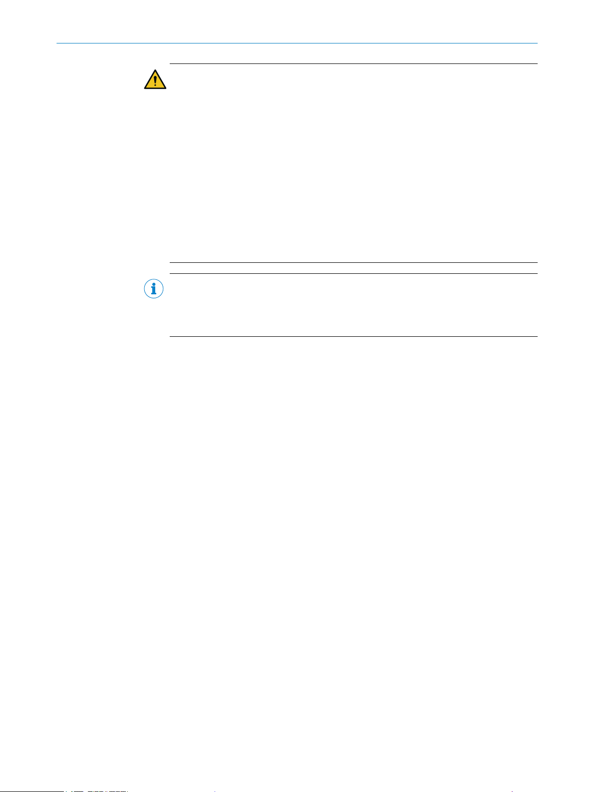
NOTE
SICK provides more information about the following explosion-proof connections:
•Joint between glass and cover
•Joint between cover and explosion-proof enclosure
SAFETY INFORMATION 2
8017025/1DVD/2023-04-28 | SICK O P E R A T I N G I N S T R U C T I O N S | C4000 Select Ex 7
Subject to change without notice

3 Mounting
This section contains instructions on how to mount the safety light curtain.
An optional alignment bracket is also available with extended adjustment possibilities,
see "Accessories", page 30.
NOTE
Mount the safety light curtain in the following order.
3.1 Safety
In addition to the information in the underlying operating instructions, please observe
the following points when mounting the safety light curtain.
DANGER
Risk of ignition or explosion
►Disconnect the voltage supply before starting to mount the explosion-proof enclo‐
sure to avoid igniting hazardous atmospheres.
►Only reconnect the voltage supply once you have completed the mounting process.
DANGER
Risk of ignition
Failure to observe this information could result in a risk of ignition.
►If the device is used in an environment classified as tbIIIC, tcIIIB or tcIIIC, the
cover must not be removed, not even temporarily (e.g. for maintenance purposes).
DANGER
Risk of ignition or explosion
►If you have to remove the cover when working on the safety light curtain, make
sure that the joints and o-ring are clean and undamaged before refitting the cover.
DANGER
Risk of ignition or explosion
►The safety light curtain must be mounted so that there is a gap of more than
30mm between all other objects and the flange joints between the housing and
the cover.
DANGER
Dangerous state of the machine
►Make sure that the dangerous state of the machine is (and remains) switched off
during mounting, electrical installation, and commissioning.
►Make sure that the outputs of the safety light curtain do not affect the machine
during mounting, electrical installation, and commissioning.
3 MOUNTING
8O P E R A T I N G I N S T R U C T I O N S | C4000 Select Ex 8017025/1DVD/2023-04-28 | SICK
Subject to change without notice

DANGER
Risk of ineffectiveness of the protective device
Persons or parts of the body to be protected are not recognized in case of non-obser‐
vance.
►Only use brackets recommended by SICK for mounting.
►Take appropriate measures for vibration dampening if the vibration and shock
requirements are above the values and test conditions specified in the data sheet,
see "Data sheet", page 25.
CAUTION
Risk of injury due to heavy weight
Lifting and moving heavy loads may cause injury.
Unsecured heavy loads may, for example, fall over and cause bruising.
►Only lift the device using equipment or two persons.
►Wear suitable protective clothing and safety shoes.
3.2 Unpacking
►Check the components for completeness and the integrity of all parts, see "Scope
of delivery", page 29.
►Please contact your respective SICK subsidiary should you have any complaints.
3.3 Installation
DANGER
Risk of ignition or explosion
►Disconnect the voltage supply before starting to mount the explosion-proof enclo‐
sure to avoid igniting hazardous atmospheres.
►Only reconnect the voltage supply once you have completed the mounting process.
DANGER
Risk of ignition
Failure to observe this information could result in a risk of ignition.
►If the device is used in an environment classified as tbIIIC, tcIIIB or tcIIIC, the
cover must not be removed, not even temporarily (e.g. for maintenance purposes).
DANGER
Risk of ignition or explosion
►If you have to remove the cover when working on the safety light curtain, make
sure that the joints and o-ring are clean and undamaged before refitting the cover.
The mounting process is comprised of either three or four stages:
1. If you have purchased the safety light curtain in pre-mounted condition, please
skip this step.
First mount the C4000 Select safety light curtain in the explosion-proof enclosure
using the two swivel mount brackets supplied. The swivel mount bracket makes
it possible to rotate the sender and receiver around the axis of the device and to
align them accurately.
MOUNTING 3
8017025/1DVD/2023-04-28 | SICK O P E R A T I N G I N S T R U C T I O N S | C4000 Select Ex 9
Subject to change without notice

2. Install the cable glands if necessary.
3. Secure the handles supplied onto the enclosure cover.
4. Mount the safety light curtain in the explosion-proof enclosure on the machine.
The explosion-proof enclosure can either be attached directly or using the align‐
ment bracket (available as an accessory, see "Accessories", page 30).
NOTE
►Read this section in full before mounting the safety light curtain.
►Read the section "Aligning the sender and receiver", page 22.
3.3.1 Mount the safety light curtain in the explosion-proof enclosure (only if the safety light curtain is
used in North America)
NOTE
If the device in pre-mounted condition has been purchased, please skip this section.
DANGER
Risk of ignition or explosion
►Use fixing screws with a yield point of at least 640MPa to attach the cover to the
explosion-proof enclosure.
NOTE
Only safety light curtains with a resolution of 30mm are suitable for mounting in the
explosion-proof enclosure.
1. Unscrew the fixing screws on the cover and remove the cover from the explosion-
proof enclosure.
2. Attach the swivel mount brackets to the upper and lower end caps on the safety
light curtain.
3. Position the safety light curtain in the explosion-proof enclosure so that the con‐
necting cable is at the same end of the explosion-proof enclosure as the 3/4" NPT
opening.
4. Using the fixing screws supplied, attach the swivel mount brackets to the mounting
holes provided in the explosion-proof enclosure.
5. Tighten the fixing screws on the swivel mount brackets with a torque of 2.5 to 3
Nm. Too high a torque could damage the swivel mount brackets while too low a
torque does not provide sufficient protection against vibration.
3 MOUNTING
10 O P E R A T I N G I N S T R U C T I O N S | C4000 Select Ex 8017025/1DVD/2023-04-28 | SICK
Subject to change without notice

Figure 1: Mount the safety light curtain in the explosion-proof enclosure
1
2
Figure 2: Align the safety light curtain in the explosion-proof enclosure
1Measure the distance from the end of the cover to the first rib.
2Detailed view
MOUNTING 3
8017025/1DVD/2023-04-28 | SICK O P E R A T I N G I N S T R U C T I O N S | C4000 Select Ex 11
Subject to change without notice
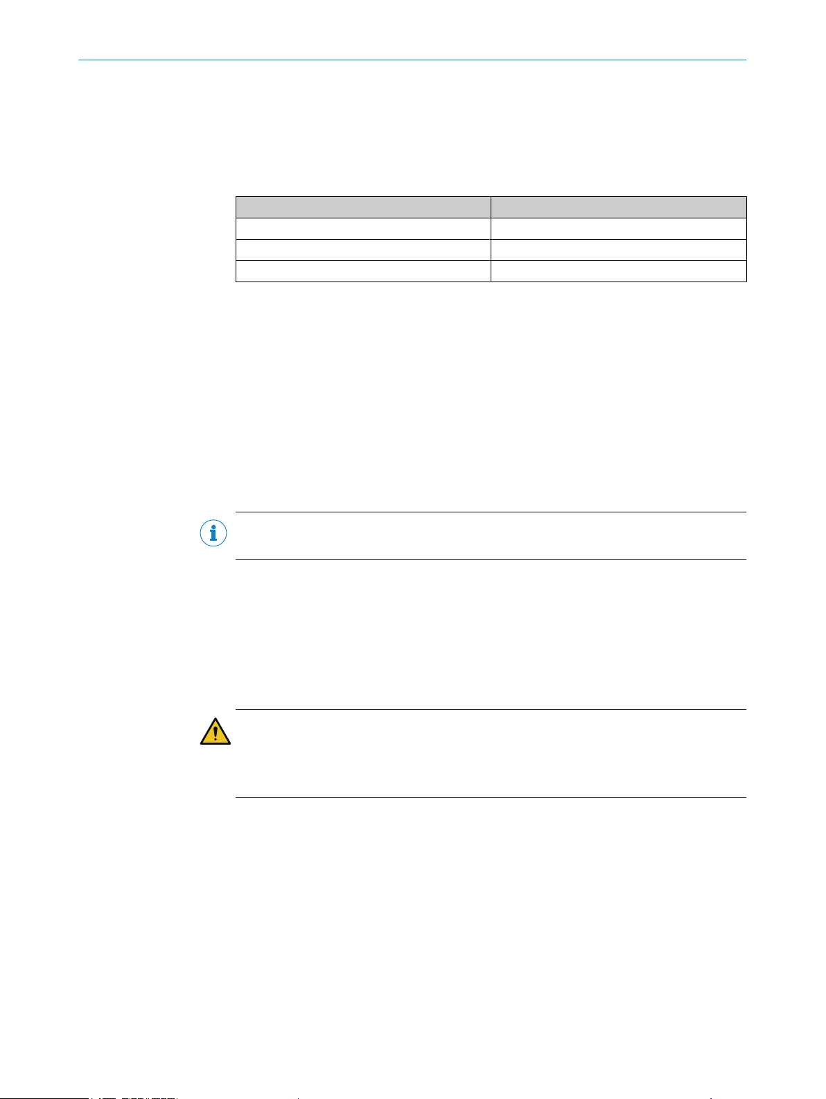
6. Align the safety light curtain in the explosion-proof enclosure so that it meets the
following criteria:
°Each rib in the window on the cover must cover no more than one optical
lens.
°Depending on the protective field height, the first rib on the side of the
connection must cover the following optical lenses:
Protective field height Optical lenses covered
600 mm Tenth optical lens
900 mm Second optical lens
1,200 mm Second optical lens
7. Turn the safety light curtain in the swivel mount brackets so that the front screen
of the safety light curtain faces the opening in the explosion-proof enclosure.
The infra-red rays must be able to pass through the window in the cover without
obstruction.
8. Tighten the screws used to secure the safety light curtain in the swivel mount
brackets with a torque of 2.5 to 3Nm.
9. Guide the connecting cable through the 3/4" NPT opening. Make sure that the
thread for the 3/4" NPT opening is not damaged.
10. If a cable gland is required, follow the instructions to mount the gland, see "Mount‐
ing the optional cable gland", page 12.
11. Fit the cover to the explosion-proof enclosure using the supplied fixing screws and
washers. Tighten the fixing screws with a torque of 11.5 to 14.5Nm.
NOTE
The washers must be used to obtain enclosure rating IP 66.
3.3.2 Mounting the optional cable gland
Depending on national regulations and requirements, a cable gland may have to be
installed. The cable gland is available as an accessory.
1. Guide the cable through the cable gland.
2. Screw the cable gland into the 3/4" NPT opening on the explosion-proof enclosure.
3. Pull the collar on the cable gland so that the cable is securely attached.
DANGER
Risk ofignition or explosion
►Check the 3/4" NPT opening on the thread for damage.
►Do not use the device if the thread for the 3/4" NPT opening is damaged.
3.3.3 Mounting the handles onto the cover of the explosion-proof enclosure
1. Use the supplied M6 screws to secure the two handles onto the cover of the
explosion-proof enclosure.
2. Tighten the screws with a torque of 4.5 to 5 Nm.
3 MOUNTING
12 O P E R A T I N G I N S T R U C T I O N S | C4000 Select Ex 8017025/1DVD/2023-04-28 | SICK
Subject to change without notice

Figure 3: Mounting the two handles
3.3.4 Mounting the safety light curtain
General notes
►Find a place to mount the safety light curtain that is stable enough to hold its
weight.
►Mount the sender and receiver on a level surface.
►Mount the sender and receiver at the same height.
►The end with the connecting cable must point in the same direction for both
devices.
Figure 4: The sender and receiver are mounted incorrectly
MOUNTING 3
8017025/1DVD/2023-04-28 | SICK O P E R A T I N G I N S T R U C T I O N S | C4000 Select Ex 13
Subject to change without notice
►Sender and receiver must not be installed at 180° rotated relative to each other.
►Make sure that the sender and receiver are aligned correctly. The optical lens
systems of the sender and the receiver must be located opposite one another.
►If necessary, use a water level to check that the components are parallel.
►The alignment bracket makes it possible to rotate the sender and receiver around
the axis of the device and to align them accurately, see "Aligning the sender and
receiver", page 22.
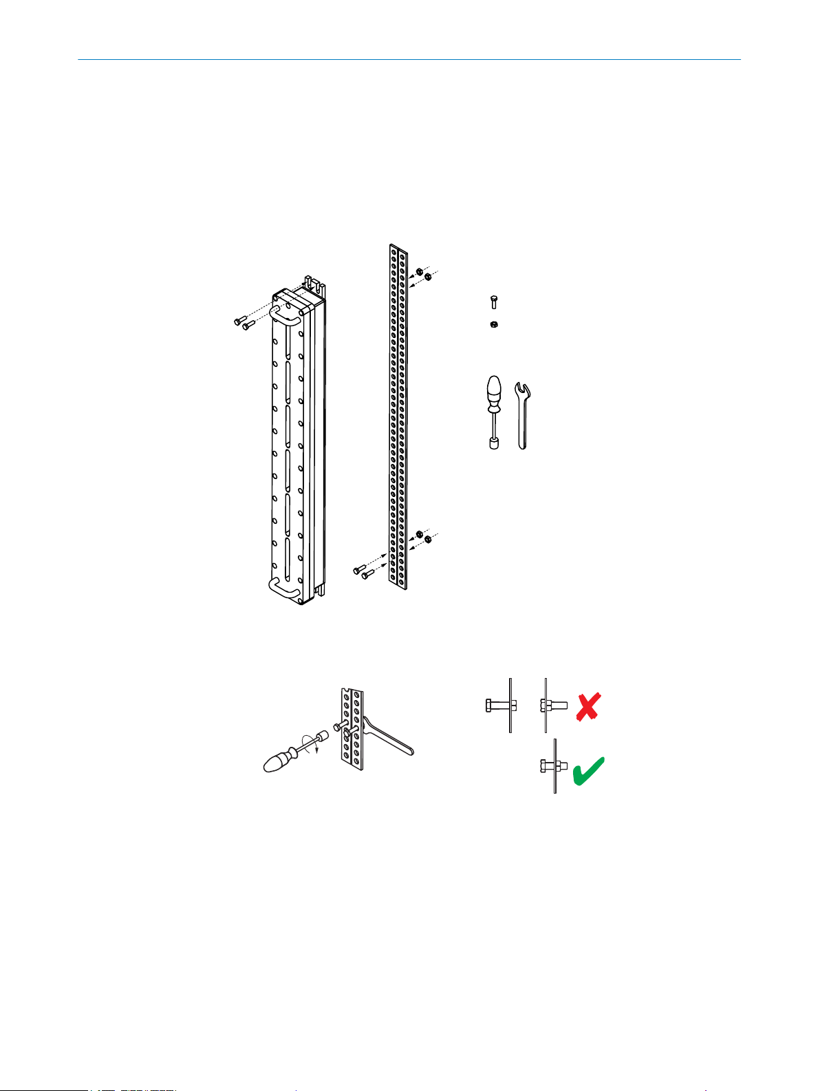
Mounting the safety light curtain without the alignment bracket
4 x
4 x
WS
13 mm
Scope of delivery
Required tools
Figure 5: Mounting the safety light curtain without the alignment bracket
►Use wrench size 13 mm.
Figure 6: Mounting the safety light curtain without the alignment bracket: Step 1
1. Using 6 to 8 revolutions, screw in the two M8 screws for mounting the lower end
of the explosion-proof enclosure. Make sure you leave enough space between
the screws and the mounting surface for the lower end of the explosion-proof
enclosure.
3 MOUNTING
14 O P E R A T I N G I N S T R U C T I O N S | C4000 Select Ex 8017025/1DVD/2023-04-28 | SICK
Subject to change without notice

Figure 7: Mounting the safety light curtain without the alignment bracket: Step 2
2. Position the explosion-proof enclosure on the two screws so that the mounting
holes are directly over the partly-tightened screws.
Figure 8: Mounting the safety light curtain without the alignment bracket: Steps 3 and 4
3. Fix the upper end of the explosion-proof enclosure to the mounting surface using
two M8 screws.
4. Tighten the two lower M8 screws.
MOUNTING 3
8017025/1DVD/2023-04-28 | SICK O P E R A T I N G I N S T R U C T I O N S | C4000 Select Ex 15
Subject to change without notice

Mounting the safety light curtain using the alignment brackets
2 x
Part no. 2072525
4 x
4 x
4 x
WS
13 mm
Scope of delivery
Required tools
Figure 9: Mounting the safety light curtain using the alignment brackets
Figure 10: Assembling the alignment brackets
3 MOUNTING
16 O P E R A T I N G I N S T R U C T I O N S | C4000 Select Ex 8017025/1DVD/2023-04-28 | SICK
Subject to change without notice

1. Mount the lower alignment bracket so that the threaded hole faces up and the
head of the lock screw faces down.
2. Rotate the alignment bracket as far to one side as possible. Secure the alignment
bracket on the open side by screwing the first M8 screw into the through hole.
3. Rotate the lower alignment bracket to the other side. Secure the alignment bracket
using the second M8 screw.
4. Mount the upper alignment bracket so that the threaded hole faces down and the
head of the lock screw faces up.
5. Rotate the upper alignment bracket as far to one side as possible. Secure the
alignment bracket on the open side by screwing the first M8 screw into the
through hole.
6. Rotate the upper alignment bracket to the other side. Secure the alignment
bracket using the second M8 screw.
Figure 11: Mounting the safety light curtain using the alignment brackets: Steps 1 to 6
7. Using 6 to 8 revolutions, screw the two M8 screws for mounting the lower end
of the explosion-proof enclosure into the lower alignment bracket. Make sure you
leave enough space between the screws and the alignment bracket for the lower
end of the explosion-proof enclosure.
Figure 12: Mounting the safety light curtain using the alignment brackets: Step 7
8. Position the explosion-proof enclosure on the two screws so that the mounting
holes are directly over the partly-tightened screws.
MOUNTING 3
8017025/1DVD/2023-04-28 | SICK O P E R A T I N G I N S T R U C T I O N S | C4000 Select Ex 17
Subject to change without notice

Figure 13: Mounting the safety light curtain using the alignment brackets: Step 8
9. Fix the upper end of the explosion-proof enclosure to the upper alignment bracket
using two M8 screws.
10. Tighten the two lower screws.
Figure 14: Mounting the safety light curtain using the alignment brackets: Steps 9 and 10
11. Turn the safety light curtains so that they face one another and so that the
receiver receives the strongest signal possible.
3 MOUNTING
18 O P E R A T I N G I N S T R U C T I O N S | C4000 Select Ex 8017025/1DVD/2023-04-28 | SICK
Subject to change without notice

28 Nm to 28.5 Nm
28 Nm to 28.5 Nm
Figure 15: Mounting the safety light curtain using the alignment brackets: Steps 11 and 12
12. Tighten the locking screws on all alignment brackets with a torque of 28 to
28.5Nm in order to secure the safety light curtain in this position.
MOUNTING 3
8017025/1DVD/2023-04-28 | SICK O P E R A T I N G I N S T R U C T I O N S | C4000 Select Ex 19
Subject to change without notice

4 Electrical installation
4.1 Safety
In addition to the information in the underlying operating instructions, please observe
the following points when installing the electrics for the safety light curtain.
DANGER
Ignition Hazard
Failure to observe this information could result in a risk of ignition
►Always switch the voltage supply off before disconnecting a connecting cable from
the device.
►Ensure that all electrical connections to the device or to the connections are
protected.
►The IP enclosure rating for the connections and therefore for the device is only
guaranteed if the connections are protected. Otherwise foreign objects can get
into the terminal compartment. This can cause an explosion the next time the
device is switched on.
►Put in place measures for ensuring supply reliability and delivery dependability.
DANGER
Risk of ignition
Failure to observe this information could result in a risk of ignition.
►If the device is used in an environment classified as tbIIIC, tcIIIB or tcIIIC, the
cover must not be removed, not even temporarily (e.g. for maintenance purposes).
DANGER
Risk of ignition or explosion
►If you have to remove the cover when working on the safety light curtain, make
sure that the joints and o-ring are clean and undamaged before refitting the cover.
DANGER
Risk of ignition or explosion
►Disconnect the power supply before opening the explosion-proof enclosure to
avoid igniting hazardous atmospheres.
►Do not reconnect the power supply until you have completed the electrical installa‐
tion.
4 ELECTRICAL INSTALLATION
20 O P E R A T I N G I N S T R U C T I O N S | C4000 Select Ex 8017025/1DVD/2023-04-28 | SICK
Subject to change without notice
Other manuals for C4000 Select
5
Table of contents
Other SICK Lighting Equipment manuals

SICK
SICK deTec4 Core User manual

SICK
SICK C 4000 Series User manual

SICK
SICK C 4000 User manual

SICK
SICK deTec4 Core User manual

SICK
SICK deTec4 Core User manual

SICK
SICK C4-RD User manual

SICK
SICK deTec4 Core User manual

SICK
SICK deTec4 Core User manual

SICK
SICK C4-RD User manual

SICK
SICK deTem4 Core Ex User manual


Popular Lighting Equipment manuals by other brands

Lightolier
Lightolier Calculite C6P30MH specification

Flash
Flash FL-233 BEAM user manual

Vision & Control
Vision & Control LDLF60x240-W5K7/UDC Instructions for use

EuroLite
EuroLite LED KLS-2001 user manual

OMEZ LIGHTING
OMEZ LIGHTING Titan Wash 36*4 in 1 Moving Heads User instructions

HERA
HERA DS-2 User manual & installation guide


