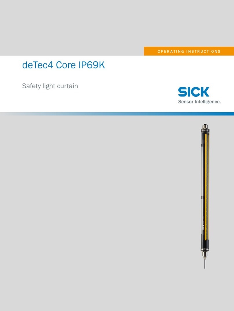
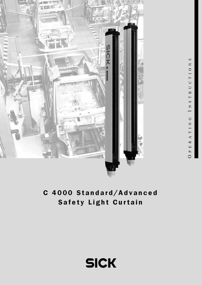
SICK C 4000 Series User manual

OPERATING INSTRUCTIONS
Safety Light Curtain
C 4000

Operating Instructions
C 4000
2©SICK AG • Safety Systems • Germany • All rights reserved 8 009 221/16-11-00

Operating Instructions
C4000
8 009 221/16-11-00 ©SICK AG • Safety Systems • Germany • All rights reserved 3

Operating Instructions
C 4000
List of contents
4©SICK AG • Safety Systems • Germany • All rights reserved 8 009 221/16-11-00
List of contents
1 About this document .................................................................................................................. 6
1.1 Function of this document ..................................................................................... 6
1.2 Target group ............................................................................................................ 6
1.3 Information depth ................................................................................................... 6
1.4 Abbreviations .......................................................................................................... 7
1.5 Symbols used .......................................................................................................... 7
2 On safety ........................................................................................................................................ 8
2.1 Specialist personnel ............................................................................................... 8
2.2 Range of uses of the device .................................................................................. 8
2.3 Proper use ............................................................................................................... 8
2.4 General protective notes and protective measures ............................................ 9
2.5 Protection of the environment ............................................................................... 9
3 Product description .................................................................................................................. 10
3.1 Special features .................................................................................................... 10
3.2 Mode of function of the device ............................................................................ 10
3.2.1 Components of the device ...................................................................... 10
3.2.2 The light curtain principle ........................................................................ 11
3.2.3 Cascading ................................................................................................. 11
3.3 Examples of range of use .................................................................................... 12
3.4 Configurable functions ......................................................................................... 12
3.4.1 Restart interlock ....................................................................................... 13
3.4.2 External device monitoring (EDM) .......................................................... 14
3.4.3 Beam coding ............................................................................................ 14
3.4.4 Scanning range ........................................................................................ 15
3.4.5 Fixed blanking .......................................................................................... 16
3.4.6 Floating blanking ...................................................................................... 17
3.4.7 Reduced resolution .................................................................................. 19
3.5 Indicator elements ............................................................................................... 20
3.5.1 Operation status indicators of the sender ............................................. 20
3.5.2 Indicator elements of the receiver .......................................................... 21
4 Installation and mounting ....................................................................................................... 22
4.1 Determining the safety distance ......................................................................... 22
4.1.1 Safety distance from the hazardous area .............................................. 22
4.1.2 Minimum distance from reflecting surfaces .......................................... 24
4.2 Steps for mounting the device ............................................................................ 25
4.2.1 Mounting with swivel mount bracket ...................................................... 26
4.2.2 Mounting with side bracket ..................................................................... 28
5 Electrical installation ................................................................................................................ 30
5.1 System connection M26×11 + FE ...................................................................... 30
5.2 Configuration connection
M8×4 (serial interface) ........................................................................................ 31
5.3 Extension connection M26×11 + FE .................................................................. 32
5.4 External Device Monitoring (EDM) ....................................................................... 33
5.5 Reset button/restart button ................................................................................ 34

Operating Instructions
C4000
List of contents
8 009 221/16-11-00 ©SICK AG • Safety Systems • Germany • All rights reserved 5
6 Commissioning ........................................................................................................................... 35
6.1 Display sequence during power-up ..................................................................... 35
6.2 Aligning sender and receiver ............................................................................... 35
6.3 Test notes ............................................................................................................. 36
6.3.1 Tests before the first commissioning ..................................................... 36
6.3.2 Regular inspection of the protective device by qualified personnel .... 36
6.3.3 Daily function checks of the protective device ..................................... 37
7 Configuration .............................................................................................................................. 38
7.1 Delivery status ...................................................................................................... 38
7.2 Preparing the configuration ................................................................................ 38
8 Care and maintenance ............................................................................................................. 39
9 Fault diagnosis ........................................................................................................................... 40
9.1 What to do in case of faults ................................................................................ 40
9.2 SICK Support ........................................................................................................ 40
9.3 Error displays of the LEDs ................................................................................... 40
9.4 Error displays of the 7-segment display ............................................................. 41
9.5 Extended diagnosis .............................................................................................. 42
10 Technical specifications ......................................................................................................... 43
10.1 Data sheet ............................................................................................................ 43
10.2 Response time ..................................................................................................... 45
10.3 Table of weights ................................................................................................... 47
10.4 Dimensional drawings ......................................................................................... 48
10.4.1 Standard system (not cascadable) ........................................................ 48
10.4.2 Cascadable system ................................................................................. 49
10.4.3 Swivel mount bracket .............................................................................. 50
10.4.4 Side mounting .......................................................................................... 50
10.4.5 Deflector mirror ....................................................................................... 51
11 Ordering information ................................................................................................................. 52
11.1 Delivery ................................................................................................................. 52
11.2 Standard system .................................................................................................. 53
11.2.1 Standard system without function package .......................................... 53
11.2.2 Standard system with function package B ............................................ 54
11.3 Cascadable system .............................................................................................. 55
11.3.1 Cascadable system without function package ...................................... 55
11.3.2 Cascadable system with function package B ........................................ 56
11.4 Additional front screen (welding spark guard) ................................................... 56
11.5 Deflector mirror .................................................................................................... 57
11.5.1 Deflector mirror PNS 80 for protective field width 0 … 4 m (total) ...... 57
11.5.2 Deflector mirror PNS 120 for protective field width 4 … 15 m (total) . 57
11.6 Accessories .......................................................................................................... 58
12 Annex ............................................................................................................................................ 59
12.1 Declaration of conformity .................................................................................... 59
12.2 Checklist for the manufacturer ........................................................................... 60
12.3 List of tables ......................................................................................................... 61
12.4 List of illustrations ............................................................................................... 62

Operating Instructions Chapter 1
C 4000
6©SICK AG • Safety Systems • Germany • All rights reserved 8 009 221/16-11-00
About this document
1About this document
Please read this chapter carefully before working with this documentation and the C 4000.
1.1 Function of this document
These operating instructions are designed to address the technical personnel of the
machine manufacturer or the machine operator in regards to safe mounting, installation,
parameterisation, electrical installation, commissioning, operation and maintenance of the
Safety Light Curtain C 4000.
These operating instructions do not provide instructions for operating machines in which
the safety light curtain is, or will be, integrated. Information on these items is found in the
appropriate operating instructions of the machine.
1.2 Target group
These operating instructions addresses planning engineers, developers and the operators
of plants and systems which are to be secured by one or several safety light curtains
C 4000. It also addresses persons who integrate the C 4000 into a machine, initialize its
use, or who are in charge of servicing and maintaining the unit.
1.3 Information depth
These operating instructions contain information on:
of the safety light curtain C 4000.
Planning and using safety devices such as the C 4000 also require specific technical skills
which are not conveyed in this documentation.
When operating the C 4000, the national, local and statutory rules and regulations must
be observed.
General information on health and safety at work and accident prevention using opto-elec-
tronic safety devices is found in the brochure “Safe machinery with opto-electronic protec-
tion”.
Note We also refer you to the C 4000 homepage in the Internet at
www.c4000.com
Here you will find information on:
·Sample applications
·A list of frequently asked questions on the C 4000
·These operating instructions in different languages for viewing and printing
·Installation and mounting
·Electrical installation
·Commissioning and parameterisation
·Care and maintenance
·Fault and error diagnosis and
troubleshooting
·Part numbers
·Conformity and approval

Operating Instructions Chapter 1
C4000
About this document
8 009 221/16-11-00 ©SICK AG • Safety Systems • Germany • All rights reserved 7
1.4 Abbreviations
ESPE Electro-sensitive protective equipment (e.g. C 4000)
CDS SICK Configuration & Diagnostic Software = software for the configuration of your safety
light curtain C 4000
EDM External device monitoring
OSSD Output signal switching device
1.5 Symbols used
Recommendation Recommendations are designed to give you some assistance in your decision-making proc-
ess with respect to a certain function or a technical measure.
Note Refer to notes for special features of the device.
lL@! Display indicators show the status of the 7-segment display of sender or receiver:
fConstant display of the letter F
FFlashing display of the letter F
f@2 Alternating display of F and 2
{[]}LED symbols denote a flashing LED (upright orientation, 7-segment display, bottom)
>Take action … Instructions for taking action are shown by an arrow. Carefully read and follow the instruc-
tions for action.
WARNING
Warning notice!
A warning notice indicates an actual or potential risk or health hazard. They are designed
to help you to prevent accidents.
Carefully read and follow the warning notices!
nSoftware notes show the location in the CDS (Configuration & Diagnosis Software) where
you can make the appropriate settings and adjustments. Go to the menu View,Dialogue
windows of the CDS and activate the item File Cards to view the named dialogue fields as
needed. Alternatively, the Software Assistant will guide you through the appropriate setting.
IHSender and receiver
In drawings and diagrams, the symbol sdenotes the sender and the symbol rdenotes
the receiver.
The term “dangerous state”
The dangerous state (standard term) of the machine is always shown in the drawings and
diagrams of this document as a movement of a machine part. In practical operation, there
may be a number of different dangerous states:
·Machine movements
·Electrical current carrying parts
·Visible or invisible radiation
·A combination of several risks and hazards

Operating Instructions Chapter 2
C 4000
8©SICK AG • Safety Systems • Germany • All rights reserved 8 009 221/16-11-00
On safety
2On safety
This chapter deals with your own safety and the safety of the equipment operators.
>Please read this chapter carefully before working with the C 4000 or with the machine
protected by the C 4000.
2.1 Specialist personnel
The safety light curtain C 4000 must be installed, commissioned and serviced only by spe-
cialist personnel. Specialist personnel is defined as persons who
·have undergone the appropriate technical training
and
·who have been instructed by the responsible machine operator in the operation of the
machine and the currently valid safety guidelines
and
·who have access to these operating instructions
2.2 Range of uses of the device
The safety light curtain C 4000 is an electro-sensitive protective equipment (ESPE). The
physical resolution is 14, 20, 30 or 40 mm with a maximum protective field width of 19 me-
ters (resolution 20 mm and higher). The realisable protective field height is between 300
and 1,800 mm.
The device is a Type 4 ESPE as defined by IEC 61496-1 and -2 and is therefore allowed for
use with controls in safety category 4 in compliance with EN 954. The device is suitable for
·Hazardous point protection (finger and hand protection)
·Hazardous area protection
·Access protection
Access to the hazardous area must be allowed only through the protective field. The plant/
system is not allowed to start as long as personnel are within the hazardous area. Refer to
chapter 3.3 “Examples of range of use” on page 12 for an illustration of the protection
modes.
Depending on the application, mechanical protection devices may be required in addition
to the safety light curtain.
Note The safety light curtain C 4000 operates as standalone system, comprising a sender and
receiver, or in combination with other cascadable C 4000 systems. This means that the
protective field can be adapted to suit individual safety requirements.
2.3 Proper use
The safety light curtain C 4000 must be used only as defined in the chapter 2.2 “Range of
uses of the device”. It must be used only by qualified personnel and only on the machine
where it has been installed and initialized by qualified personnel.
If the device is used for any other purposes or modified in any way – also during mounting
and installation – any warranty claim against SICK AG shall become void.

Operating Instructions Chapter 2
C4000
On safety
8 009 221/16-11-00 ©SICK AG • Safety Systems • Germany • All rights reserved 9
2.4 General protective notes and protective measures
WARNING
Safety notes
Please observe the following items in order to ensure the proper and safe use of the safety
light curtain C 4000.
·The national/international rules and regulations apply to the installation, use and recur-
ring technical inspections of the safety light curtain, in particular:
– Machine Directive 98/37 EG
– Equipment Usage Directive 89/655 EWG
– the work safety regulations/safety rules
– other relevant health and safety regulations
Manufacturers and users of the machine by which the safety light curtain is used are re-
sponsible for obtaining and observing all applicable safety regulations and rules.
·The notices, in particular the test regulations (see “Test notes” on page 36) of these op-
erating instructions (e.g. on use, mounting, installation or integration into the existing ma-
chine controller) must be observed.
·The tests must be carried out by specialist personnel or specially qualified and authorized
personnel and must be recorded and documented to ensure that the tests can be recon-
structed and retraced at any time.
·The operating instructions must be made available to the user of the machine where the
safety light curtain C 4000 is fitted. The machine operator is to be instructed in the use
of the device by specialist personnel and must be instructed to read the operating in-
structions.
·The external voltage supply of the device must be capable of buffering brief mains fail-
ures of 20 ms as specified in EN 60204. Suitable power supplies are available as acces-
sories from SICK (Siemens type series 6 EP 1).
2.5 Protection of the environment
The safety light curtain C 4000 has been designed to minimize environmental impact. It
uses only a minimum of power and natural resources.
At work, always act in an environmentally responsible manner. For this reason please note
the following information on disposal.
Disposal
>Always dispose of unserviceable or irreparable units in compliance with local/national
rules and regulations with respect to waste disposal.
>Remove the plastic panel and dispose of the aluminium housing of the light curtain as
recyclable waste.
>Dispose all electronic assemblies as special or hazardous waste. The electronic assem-
blies are easy to dismantle.
Note SICK AG will not accept unserviceable or irreparable units returned to the company.

Operating Instructions Chapter 3
C 4000
10 ©SICK AG • Safety Systems • Germany • All rights reserved 8 009 221/16-11-00
Product description
3Product description
This chapter provides information on the special feature and properties of the safety light
curtain C 4000. It describes the structure and the mode of function of the unit, in particular
the different operating modes.
>Please read this chapter before mounting, installing and commissioning the unit.
3.1 Special features
·Protective operation, optionally with internal or external machine-integrated restart
interlock
·Connecting options for the reset button
·External device monitoring (EDM)
·Beam coding
·Status display with 7-segment display
·Optional: Function package B
–Blankingseveralareas
– Blanking with tolerance of up to 2 beams
– Floating blanking
– Reduced resolution
– Monitoring the blanked area
3.2 Mode of function of the device
3.2.1 Components of the device
Fig. 1: Components
of the C 4000
Please refer to chapter 10 “Technical specifications” on page 43 for the data sheet.
Please refer to pages 48 ff. for the dimensional drawings.
Host (standard system, or
–with Guest 1 connected–
cascadable system)
Optional: 1. Guest system
(standard system, or
–with Guest 2 connected–
cascadable system)
Optional: 2. Guest system
(standard system)

Operating Instructions Chapter 3
C4000
Product description
8 009 221/16-11-00 ©SICK AG • Safety Systems • Germany • All rights reserved 11
3.2.2 The light curtain principle
The safety light curtain C 4000 consists of a sender and a receiver (figure 1). Between
these two units is the protective field, defined as the protective field height and the protec-
tive field width.
The construction size height determines the height of the protective field of the appropriate
system. The upper and lower limit of the protective field is shown by markings on the profile
sections.
The width of the protective field is derived from the length of the light path between sender
and receiver and must not exceed the maximum rated width of the protective field (see
“Technical specifications” on page 43).
Sender and receiver automatically synchronize themselves optically. An electrical connec-
tion between both these components is not required.
The C 4000 is modular in structure. All optical and electronic components and assemblies
are housed in a slim and torsionally rigid housing.
3.2.3 Cascading
To provide an effective point-of-operation guard, a maximum of three C 4000 can be con-
nected in series for cascading configuration. The device connected to the control cabinet
is the main sensor, called Host. The subsequent sensors are called Guests (cf. figure 1 on
page 10).
Benefits of cascading
·No additional external circuitry required
·Resolution and protective field height may differ among the individual systems
Limits of cascading
·The maximum protective field width must be guaranteed for each individual system!
·The maximum total number of beams must be 480 beams in non-coded operation,
and a maximum of 405 beams in coded operation.
·The maximum cable length between two cascaded systems must not exceed 3 meters.

Operating Instructions Chapter 3
C 4000
12 ©SICK AG • Safety Systems • Germany • All rights reserved 8 009 221/16-11-00
Product description
3.3 Examples of range of use
Fig. 4: Access guarding using a
safety light curtain C 4000
The safety light curtain C 4000 operates as a proper protective device only if the following
conditions are met:
·The control of the machine must be electrical.
·The dangerous state of the machine must be transferable at any time into a safe state.
·Sender and receiver unit must be so mounted that objects penetrating the hazardous
area are safely identified by the C 4000.
·The restart button must be fitted outside the hazardous area such that it cannot be
operated by a person working inside the hazardous area.
·The statutory and local rules and regulations must be observed when installing and using
the device.
3.4 Configurable functions
This chapter describes the functions of the safety light curtain C 4000 selectable via soft-
ware. Some of the functions can be combined.
WARNING
Test the protective device after any changes!
The entire protective device must be tested for proper operation after each change of the
configuration (see 6.3 on page 36).
nWhen starting to configure the device, you may save an application name with a maximum
of 22 characters. Use this function as a “memory jogger”, e.g. to describe the application
of the current device configuration.
Fig. 2 (left): Securing danger-
ous points with a safety light
curtain C 4000
Fig. 3 (right): Securing danger-
ous areas with a safety light
curtain C 4000

Operating Instructions Chapter 3
C4000
Product description
8 009 221/16-11-00 ©SICK AG • Safety Systems • Germany • All rights reserved 13
3.4.1 Restart interlock
Fig. 5: Outline drawing of the
protective operation
The dangerous state of the machine () is interrupted if the light curtain () is disrupted
and will not be reinstated () until the user actuates the restart button.
The restart interlock can be implemented in two different ways:
·With the internal restart interlock of the C 4000:
The C 4000 controls the restart.
·With the restart interlock of the machine:
The C 4000 has no control over the restart.
The possible combinations are shown in the following table:
WARNING
Always configure the C 4000 with restart interlock!
The C 4000 is unable to verify if the restart interlock of the machine is connected. If you
deactivate both the C 4000 and the machine-internal restart interlock, the users and oper-
ators of the machine will be at an acute risk of injury.
The electrical connection of the restart button is described in the chapter “Reset button/
restart button” on page 34.
nDevice symbol C 4000 receiver, context menu Configuration draft, Edit, file card General,
option Restart interlock.
Reset
If you activate both the C 4000 and the machine-internal restart interlock, each restart
interlock will have its own button designated to it.
When actuating the button for the internal restart interlock
·the C 4000 will reset its switch outputs
·the light curtain changes to green
Restart interlock of
the C 4000
Restart interlock of
the machine
Permissible application
deactivated deactivated Only if the light curtain cannot be stood
behind. Observe EN 60204-1!
deactivated activated All
activated deactivated Only if the light curtain cannot be stood
behind. Observe EN 60204-1!
activated activated All. Restart interlock of the C 4000 handles
the reset function (see below).
T
a
b
.
1
:
P
erm
i
ss
ibl
e
configuration of the restart
interlock

Operating Instructions Chapter 3
C 4000
14 ©SICK AG • Safety Systems • Germany • All rights reserved 8 009 221/16-11-00
Product description
The machine-internal restart interlock prevents the machine from restarting. This is why the
button of the internal restart interlock only fulfills the reset function in this configuration
and is called Reset Button.
After activating the reset button, the user must also press the restart button. If the reset
button and the restart button are not pressed in this specified sequence, the dangerous
status remains unchanged.
Recommendation The reset button prevents the accidental and inadvertent operation of the restart button.
The user must first acknowledge the dangerous state with the reset button.
The electrical connection of the reset button is described in chapter “Reset button/restart
button” on page 34.
3.4.2 External device monitoring (EDM)
The EDM function controls the contact elements (if used) activated by both of the device out-
puts (e.g. external contacts). The machine must be allowed to restart only if both contactors
have been opened.
The C 4000 controls the contactors after every disruption of the light path and before the
machine restart. The EDM can so identify if one of the contactors has fused, for instance.
In this case
·the error message appears 8(in the 7-segment display)
·the safety light curtain changes to red
·with the internal restart interlock activated, the safety light curtain signals by flashing yel-
low LED [“Reset required”
Note If the system is unable to change to a safe operational state (e.g. after contactor failure),
the system interlocks and shuts down completely (“Lock-out”). The 7-segment display will
then show the error message (.
The electrical connection of the EDM is described in chapter “System connection
M26×11 + FE” on page 30.
nDevice symbol C 4000 receiver, context menu Configuration draft, Edit, file card General,
option EMD
3.4.3 Beam coding
If several safety light curtains operate in close proximity to each other, the sender beams
of one system may interfere with the receiver of the other system. With code 1 or 2
activated, the receiver distinguishes the beams destined for it from other beams. The fol-
lowing settings are available: non-coded, code 1 and code 2.
WARNING
Use different beam codings if the systems are located close to each other!
Systems mounted in close proximity to each other must be operated with different beam
codings (non-coded, code 1 or code 2). If this precaution is neglected, the system may be
impaired in its protective function by the beams from the neighbouring system and so
change to the unsafe state. This would mean that the user/operator is at risk.

Operating Instructions Chapter 3
C4000
Product description
8 009 221/16-11-00 ©SICK AG • Safety Systems • Germany • All rights reserved 15
Fig. 6: Schematic layout of the
beam coding
Notes ·Beam coding increases the availability of the protected machine. Beam coding also en-
hances the resistance to optical interference such as welding sparks and similar.
·In a cascaded system, host and guest can be operated only with the same beam coding.
·Beam coding will increase the response time of the system. This may also change the re-
quired safety distance. For details refer to chapter 4.1 “Determining the safety distance”
on page 22.
·After activating the system, sender and receiver will briefly display the coding.
·If operated with beam coding, the number of beams in cascaded systems must not ex-
ceed 405 beams.
nDevice symbol C 4000 receiver or sender, context menu Configuration draft, Edit, file card
General, option Beam coding.
3.4.4 Scanning range
WARNING
aMatch the scanning range with the protective field width!
The scanning range of the system (host, guest 1 and guest 2) must be adapted to the width
of the protective field.
·If the scanning range is too small, the light curtain will not change to green.
·If the scanning range is too great, the light curtain may malfunction. This would mean that
the user/operator is at risk.
Note If you are using the additional front screen (see page 56) available as an accessory, the
useful scanning range will be reduced by 8% for each additional front screen.
The available settings depend on the physical resolution of the system:
nDevice symbol C 4000 receiver or sender, context menu Configuration draft, Edit, file card
General, option Scanning range.
Code 1
Code 2
Physical resolution Selectable
scanning ranges
Scanning range with
1 additional front
screen
Scanning range with
2 additional front
screens
14 mm 0-2.5 m
2-6 m
0-2.3 m
1.8-5.5 m
0-2.1 m
1.7-5 m
20 mm, 30 mm,
40 mm
0-6 m
2.5-19 m
0-5.5 m
2.3-17.4 m
0-5 m
2.1-16 m
T
a
b
.
2
:
Ph
ys
i
ca
l
reso
l
ut
i
on an
d
s
canning range

Operating Instructions Chapter 3
C 4000
16 ©SICK AG • Safety Systems • Germany • All rights reserved 8 009 221/16-11-00
Product description
3.4.5 Fixed blanking
Fig. 7: Schematic layout
of the fixed blanking
The light curtain C 4000 is capable of fixed-blanking one or several adjacent beams, e.g. to
allow continued operation in spite of an obstruction such as a table placed permanently in
the light path.
The blanked area will no longer be part of the protective field. Blanked objects must there-
fore be permanently located inside the blanked area (). As soon as the object is removed
from the beam path, the light curtain will send a signal to disrupt the dangerous movement
(). Protection is otherwise no longer guaranteed.
WARNING
Completely protect the blanked area!
The object must cover the entire distance between sender and receiver.
>If necessary, protect the areas to the left and right of the object against intrusion by fit-
ting mechanical barriers!
Fig. 8: Protecting a fixed blank-
ing using mechanical barriers
>Also, make sure that the object can only me removed as a whole together with the bar-
riers.
>After adapting the blanking, check the protective field with the test rod. Instructions are
found in chapter 6.3.3 on page 37.
Blanked area, sides protected by
mechanical barriers

Operating Instructions Chapter 3
C4000
Product description
8 009 221/16-11-00 ©SICK AG • Safety Systems • Germany • All rights reserved 17
Properties of fixed blanking
·The C 4000 is capable of blanking a total of four areas simultaneously. A minimum of one
beam spacing must exist between two blanked areas.
·The first beam of the light curtain (close to the 7-segment display) must not be blanked.
It is needed for the synchronisation between sender and receiver.
·For vibrating objects, you can select a position tolerance of the area of a maximum of
±2 beams.
·In addition, you can define a size tolerance of –1 beam.
Notes ·If you configure a blanked area without position and without size tolerance, the move-
ment of the object within the area is very limited before the light curtain changes to red.
·The maximum selectable tolerance values depend on the size of the blanked area: The
actual tolerance expansion in millimetres differs. It depends on the physical resolution of
the device.
·With fixed blanking, the 7-segment display indicates ras soon as sender and receiver
are aligned.
nDevice symbol C 4000 receiver, context menu Configuration draft, Edit, file card Blanking
of the appropriate system, Type of blanking = fixed. With the help of selection fields, the
size of the area and the tolerance values (in millimetres) for size and position can be
selected.
3.4.6 Floating blanking
Fig. 9: Schematic layout
of the floating blanking
The light curtain C 4000 is capable of blanking an area of two or more adjacent beams ().
In contrast to fixed blanking, the blanked area is allowed to move () without the light cur-
tain changing to red.
The blanked area will no longer be part of the protective field. Moving objects must there-
fore be permanently within the protective field (and ). As soon as the object is removed
from the protective field, the light curtain will send a signal to disrupt the dangerous move-
ment (). Protection is otherwise no longer guaranteed.
Properties of floating blanking
·The C 4000 is capable of blanking a total of four areas simultaneously.
·Fixed and floating blanking can be mixed.
·The size of the movable area must be at least equal to the effective resolution (see page
19 if you use reduced resolution).
·Areas of floating blanking must not be allowed to make contact or overlap during opera-
tion. The CDS (Configuration & Diagnostic Software) will check this automatically.

Operating Instructions Chapter 3
C 4000
18 ©SICK AG • Safety Systems • Germany • All rights reserved 8 009 221/16-11-00
Product description
·The first beam of the light curtain (close to the 7-segment display) cannot be blanked. It
is needed for the synchronisation between sender and receiver.
·Size tolerances of 1 or 2 beams may be selected for moving areas. In case of 2 beams
(increased size tolerance), the effective resolution at the edges of the moving area will be
reduced! For this reason the moving area must always be greater than the effective res-
olution at the edges of the area (see table 3).
·The size tolerance of 2 beams can be used only in devices with a physical resolution of
14 mm and 20 mm.
WARNING
Check the safety distance S!
In case of floating blanking and increased size tolerance (2 beams), the required safety dis-
tance S will depend on the effective resolution.
>If required, recalculate the safety distance and readjust it on the machine.
Example: – Physical resolution 14 mm
– Increased size tolerance (2 beams)
– Effective resolution 22 mm
Calculate the safety distance with a resolution of 22 mm.
>Mark the effective resolution on the notice label of sender and receiver.
Fig. 10: Marking the effective
resolution on the device label
Note With floating blanking, the 7-segment display indicates ras soon as sender and receiver
are aligned.
nDevice symbol C 4000 receiver, context menu Configuration draft, Edit, file card Blanking
of the appropriate system Type of blanking = floating. With the help of the selection fields,
the size of the area can be selected (in millimetres).
Physical resolution Size
tolerance
Effective resolution at the edges
of the area with floating blanking
14 mm 1 beam 14 mm
2 beams 22 mm
20 mm 1 beam 20 mm
2 beams 30 mm
30 mm 1 beam 30 mm
2 beams Not possible
40 mm 1 beam 40 mm
2 beams Not possible
T
a
b
.
3
:
Eff
ect
i
ve reso
l
ut
i
on
i
n
floating blanking with size
tolerance

Operating Instructions Chapter 3
C4000
Product description
8 009 221/16-11-00 ©SICK AG • Safety Systems • Germany • All rights reserved 19
3.4.7 Reduced resolution
Under reduced resolution, the light curtain allows the disruption of 1, 2 or 3 adjacent
beams. Objects which are not larger then specified in table table 4 may be moved through
the light curtain without the light curtain changing to red (Fig. 11, and ).
Fig. 11: Schematic outline of
the operation with reduced res-
olution (example: reduction by
one beam)
Notes ·The function Reduced Resolution can be used only in devices with a physical resolution
of 14 mm and 20 mm.
·The first beam of the light curtain (close to the 7-segment display) must not be interrupt-
ed. Otherwise, the safety light curtain will change to red.
·The system response time does not change under reduced resolution.
·With reduced resolution, the 7-segment display indicates ras soon as sender and re-
ceiver are aligned.
WARNING
Check the safety distance S!
The safety distance S required under reduced resolution depends on the effective resolu-
tion.
>If required, recalculate the safety distance and readjust it on the machine.
Example: – Physical resolution 14 mm
– Resolution reduced by 1 beam
– Effective resolution 22 mm
Calculate the safety distance with a resolution of 22 mm.
>Mark the effective resolution on the notice label of sender and receiver.
Fig. 12: Marking the effective
resolution on the device label
Physical resolution Reduction Effective resolution Maximum size of
movable objects
14 mm 1 beam 22 mm 10 mm
2 beams 30 mm 18 mm
3 beams 37 mm 25 mm
20 mm 1 beam 30 mm 14 mm
2 beams 40 mm 24 mm
3 beams Not possible —
SS
T
a
b
.
4
:
Eff
ect
i
ve reso
l
ut
i
on an
d
maximum size of moving
objects under reduced
resolution

Operating Instructions Chapter 3
C 4000
20 ©SICK AG • Safety Systems • Germany • All rights reserved 8 009 221/16-11-00
Product description
3.5 Indicator elements
The LEDs and the 7-segment display of sender and receiver signal the operating status of
the C 4000.
3.5.1 Operation status indicators of the sender
Fig. 13: Indicator elements
of the sender
Display Meaning
[Yellow: Power supply OK
eSystem error. The device is defective. Replace the sender.
oThe device is in the test mode.
uNon-coded operation (only after switching on)
-Operation with code 1 (only after switching on)
,Operation with code 2 (only after switching on)
Other
displays
All other displays are error messages. Please refer to chapter “Fault
diagnosis” on page 40.
Yellow
7-segment display
Tab. 5: Meaning of the
operation indicator elements
of the sender
Table of contents
Other SICK Lighting Equipment manuals
SICK
SICK deTec2 Core User manual
SICK
SICK deTec4 Core User manual
SICK
SICK deTec4 Core User manual
SICK
SICK C4000 Advanced Ex User manual

SICK
SICK C4000 Select User manual
SICK
SICK C4-RD User manual

SICK
SICK C4-RD User manual
SICK
SICK deTec4 Core User manual
SICK
SICK deTem4 Core Ex User manual
SICK
SICK C 4000 User manual
