SICK C 4000 User manual
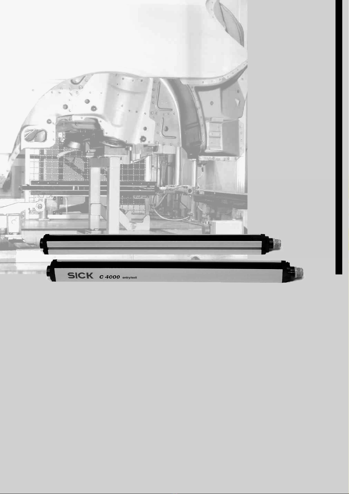
C4000 Entry/Exit
Safety Light Curtain
O
P E R A T I N G IN S T R U C T I O N S

Operating Instructions
C4000 Entry/Exit
2©SICK AG • Industrial Safety Systems • Germany • All rights reserved 8 010 241/NA55/23-10-03
This document is protected by the law of copyright, whereby all rights established therein remain with the com-
pany SICK AG. Reproduction of this document or parts of this document is only permissible within the limits of the
legal determination of Copyright Law. Alteration or abridgement of the document is not permitted without the ex-
plicit written approval of the company SICK AG.

Operating Instructions
C4000 Entry/Exit
8010 241/NA55/23-10-03 © SICK AG • Industrial Safety Systems • Germany • All rights reserved 3
Contents
Contents
1About this document .......................................................................................................................... 5
1.1 Function of this document ........................................................................................5
1.2 Target group...............................................................................................................5
1.3 Scope..........................................................................................................................5
1.4 Depth of information .................................................................................................5
1.5 Abbreviations .............................................................................................................6
1.6 Symbols used.............................................................................................................6
2 n safety ................................................................................................................................................. 8
2.1 Specialist personnel ..................................................................................................8
2.2 Applications of the device .........................................................................................8
2.3 Correct use.................................................................................................................9
2.4 General safety notes and protective measures.......................................................9
2.5 Environmental protection........................................................................................10
3 Product description...........................................................................................................................11
3.1 Special features.......................................................................................................11
3.2 Operating principle of the device............................................................................11
3.2.1 Device components.....................................................................................11
3.2.2 The light curtain principle ...........................................................................12
3.3 Examples of range of use........................................................................................12
3.4 Status indicators......................................................................................................13
3.4.1 Status indicators of the sender ..................................................................13
3.4.2 Status indicators of the receiver ................................................................14
4 Configurable functions.....................................................................................................................15
4.1 Restart interlock ......................................................................................................15
4.2 External device monitoring (EDM) ..........................................................................16
4.3 Emergency stop .......................................................................................................16
4.4 Signal output (ADO) .................................................................................................17
4.5 Beam coding ............................................................................................................18
4.6 Scanning range........................................................................................................18
4.7 Multiple sampling ....................................................................................................19
4.8 Self-teach dynamic blanking...................................................................................20
4.9 Sender test...............................................................................................................23
5 Installation and mounting ...............................................................................................................24
5.1 Determining the safety distance.............................................................................24
5.1.1 Safety distance from the hazardous point.................................................24
5.1.2 Minimum distance to reflective surfaces ..................................................26
5.2 Steps for mounting the device................................................................................27
5.2.1 Mounting with swivel mount bracket .........................................................28
5.2.2 Mounting with side bracket ........................................................................30
6 Electrical installation........................................................................................................................32
6.1 System connection M26×11 + FE .........................................................................33
6.2 Configuration connection M8× 4 (serial interface) ................................................34
6.3 Extension connection M26×11 + FE .....................................................................35
6.4 External device monitoring (EDM) ..........................................................................36
6.5 Reset button ............................................................................................................37
6.6 Emergency stop .......................................................................................................38
6.7 Signal output (ADO) .................................................................................................39
6.8 Test input (sender test) ...........................................................................................39

Operating Instructions
C4000 Entry/Exit
4©SICK AG • Industrial Safety Systems • Germany • All rights reserved 8 010 241/NA55/23-10-03
Contents
7 Commissioning....................................................................................................................................40
7.1 Display sequence during start-up........................................................................... 40
7.2 Aligning sender and receiver .................................................................................. 40
7.3 Test notes ................................................................................................................ 41
7.3.1 Tests before the first commissioning ........................................................ 41
7.3.2 Regular inspection of the protective device by qualified personnel........ 41
7.3.3 Daily functional checks of the protective device ......................................42
8 Configuration .......................................................................................................................................43
8.1 Default delivery status ............................................................................................ 43
8.2 Preparing the configuration.................................................................................... 43
9 Care and maintenance .....................................................................................................................44
10 Fault diagnosis....................................................................................................................................45
10.1 In the event of faults or errors................................................................................ 45
10.2 SICK support............................................................................................................ 45
10.3 Error displays of the diagnostics LEDs................................................................... 45
10.4 Error displays of the 7-segment display................................................................. 46
10.5 Extended diagnostics.............................................................................................. 48
11 Technical specifications..................................................................................................................49
11.1 Data sheet ............................................................................................................... 49
11.2 Response time ........................................................................................................ 52
11.3 Table of weights ...................................................................................................... 54
11.3.1 C 4000 Entry/Exit ....................................................................................... 54
11.3.2 Deflector mirrors PNS 75 and PNS 125.................................................... 54
11.4 Dimensional drawings ............................................................................................ 55
11.4.1 C 4000 Entry/Exit without extension connection ..................................... 55
11.4.2 C 4000 Entry/Exit with extension connection........................................... 56
11.4.3 Swivel mount bracket ................................................................................. 57
11.4.4 Side bracket ................................................................................................ 57
11.4.5 Deflector mirror PNS 75 ............................................................................. 58
11.4.6 Deflector mirror PNS 125........................................................................... 59
12 rdering information .........................................................................................................................60
12.1 Delivery .................................................................................................................... 60
12.2 C 4000 Entry/Exit.................................................................................................... 60
12.3 Additional front screen (weld spark guard)............................................................ 60
12.4 Deflector mirror ....................................................................................................... 61
12.4.1 Deflector mirror PNS 75 for protective field width 0 … 4 m (total) .......... 61
12.4.2 Deflector mirror PNS 125 for protective field width 4 … 15 m (total) ..... 61
12.5 Accessories.............................................................................................................. 62
13 Annex......................................................................................................................................................63
13.1 Declaration of conformity ....................................................................................... 63
13.2 Manufacturer’s checklist ........................................................................................ 64
13.3 List of tables............................................................................................................ 65
13.4 List of illustrations................................................................................................... 66

Operating Instructions Chapter 1
C4000 Entry/Exit
8010 241/NA55/23-10-03 © SICK AG • Industrial Safety Systems • Germany • All rights reserved 5
About this document
1About this document
Please read this chapter carefully before working with the documentation and the C 4000
Entry/Exit, also referred to in the following as C 4000 for short.
1.1 Function of this document
These operating instructions are designed to address the technical personnel of the
machine manufacturer or the machine operator in regards to safe mounting, installation,
configuration, electrical installation, commissioning, operation and maintenance of the
safety light curtain C 4000.
These operating instructions do not provide instructions for operating machines on which
the safety light curtain is, or will be, integrated. Information on this is to be found in the
appropriate operating instructions for the machine.
1.2 Target group
These operating instructions are addressed to planning engineers,developers and opera-
tors of plants and systems which are to be protected by one or several C 4000 safety light
curtains. It also addresses people who integrate the C 4000 into a machine, initialise its
use, or who are in charge of servicing and maintaining the device.
1.3 Scope
These operating instructions apply to the safety light curtain C 4000 Entry/Exit with the
following entry on the type label in the field Operating Instructions: 8 010 235. This docu-
ment is part of SICK part number 8 010 235 (operating instructions “C 4000 Entry/Exit
Safety Light Curtain” in all available languages).
For the configuration and diagnostics of these devices you require CDS (Configuration &
Diagnostic Software) version 2.10 or higher. To check the version of the software, on the
?menu select Info....
1.4 Depth of information
These operating instructions contain information on:
installation and mounting
electrical installation
commissioning and configuration
care and maintenance
fault, error diagnosis and trouble-
shooting
part numbers
conformity and approval
of the safety light curtain C 4000.
Planning and using protective devices such as the C 4000 also require specific technical
skills which are not detailed in this documentation.
When operating the C 4000, the national, local and statutory rules and regulations must
be observed.
General information on accident prevention using opto-electronic protective devices can
be found in the brochure “Safe Machines with opto-electronic protective devices”.
Note

Chapter 1Operating Instructions
C4000 Entry/Exit
6©SICK AG • Industrial Safety Systems • Germany • All rights reserved 8 010 241/NA55/23-10-03
About this document
We also refer you to the SICK homepage on the Internet at
www.sick.com
Here you will find information on:
sample applications
alist of frequently asked questions regarding the C 4000
these operating instructions in different languages for viewing and printing
certificates on the prototype test, the EC declaration of conformity and other documents
1.5 Abbreviations
Application diagnostic output = configurable signal output that indicates a specific status
of the protective device
Electro-sensitive protective equipment (e.g. C 4000)
SICK Configuration & Diagnostic Software
External device monitoring
Enhanced function interface = safe SICK device communication
Output signal switching device
1.6 Symbols used
Recommendations are designed to give you some assistance in your decision-making
process with respect to a certain function or a technical measure.
Refer to notes for special features of the device.
Display indicators show the status of the 7-segment display of sender or receiver:
Constant indication of characters, e.g. U
Flashing indication of characters, e.g. 8
Alternating indication of characters, e.g. L and 2
The depiction of numbers on the 7-segment display can be rotated by 180° with the aid of
the CDS. In this document the depiction of the numbers on the 7-segment display is how-
ever always in the normal, non-rotated position.
LED symbols describe the state of a diagnostics LED. Examples:
Red The red LED is illuminated constantly.
Yellow The yellow LED is flashing.
Green The green LED is off.
Instructions for taking action are shown by an arrow. Read carefully and follow the instruc-
tions for action.
Warning!
Awarning indicates an actual or potential risk or health hazard. They are designed to help
you to prevent accidents.
Read carefully and follow the warning notices!
Note
AD
ESPE
CDS
EDM
EFI
SSD
Recommendation
Note
,
Red,Yellow,
Green
Take action …
WARNING

Operating Instructions Chapter 1
C4000 Entry/Exit
8010 241/NA55/23-10-03 © SICK AG • Industrial Safety Systems • Germany • All rights reserved 7
About this document
Software notes show the location in the CDS (Configuration & Diagnostic Software) where
you can make the appropriate settings and adjustments. In the CDS open the menu View,
Dialog box and select the item File cards to go straight to the above dialog fields. Alter-
natively, the software wizard will guide you through the appropriate setting.
If you use the SICK switching amplifier UE 402, you will find the functions under the same
names, however to some extent in different places in the CDS Configuration dialog box.
This is dependent on the scope of the related function. The operating instructions for the
UE 402 contain detailed information.
Sender and receiver
In drawings and diagrams, the symbol denotes the sender and the symbol denotes
the receiver.
The term “dangerous state”
The dangerous state (standard term) of the machine is always shown in the drawings and
diagrams of this document as a movement of a machine part. In practical operation, there
may be a number of different dangerous states:
machine movements
electrical conductors
visible or invisible radiation
a combination of several risks and hazards

Chapter 2Operating Instructions
C4000 Entry/Exit
8©SICK AG • Industrial Safety Systems • Germany • All rights reserved 8 010 241/NA55/23-10-03
n safety
2n safety
This chapter deals with your own safety and the safety of the equipment operators.
Please read this chapter carefully before working with the C 4000 or with the machine
protected by the C 4000.
2.1 Specialist personnel
The safety light curtain C 4000 must be installed, commissioned and serviced only by
specialist personnel. Specialist personnel are defined as persons who
have undergone the appropriate technical training
and
who have been instructed by the responsible machine operator in the operation of the
machine and the current valid safety guidelines
and
who have access to these operating instructions.
2.2 Applications of the device
The safety light curtain C 4000 is an electro-sensitive protective equipment (ESPE).
The physical resolution is 14, 20, 30 or 40 mm with a maximum protective field width of
19 metres (resolution 20 mm and higher). The realisable protective field length is between
900 and 1,500 mm.
The device is a Type 4 ESPE as defined by IEC 61496-1 and -2 and is therefore allowed for
use with controls in control category 4 in compliance with EN 954-1. The device is suitable
for
hazardous area protection
access protection
Access to the hazardous point must be allowed only through the protective field. The
plant/system is not allowed to start as long as personnel are within the hazardous area.
Refer to chapter 3.3 “Examples of range of use” on page 12 for an illustration of the
protection modes.
nly use the safety light curtain as an indirect protective measure!
An opto-electronic protective device provides indirect protection, e.g., by switching off the
power at the source of the hazard. It cannot provide protection from parts thrown out, nor
from emitted radiation. Transparent objects are not detected.
Depending on the application, mechanical protective devices may be required in addition
to the safety light curtain.
The safety light curtain C 4000 Entry/Exit cannot be cascaded.
WARNING
Note

Operating Instructions Chapter 2
C4000 Entry/Exit
8010 241/NA55/23-10-03 © SICK AG • Industrial Safety Systems • Germany • All rights reserved 9
n safety
2.3 Correct use
The safety light curtain C 4000 must be used only as defined in chapter 2.2 “Applications
of the device”. It must be used only by qualified personnel and only on the machine where
it has been installed and initialised by qualified personnel in accordance with these operat-
ing instructions.
If the device is used for any other purposes or modified in any way — also during mounting
and installation — any warranty claim against SICK AG shall become void.
2.4 General safety notes and protective measures
Safety notes
Please observe the following procedures in order to ensure the correct and safe use of the
safety light curtain C 4000.
The national/international rules and regulations apply to the installation, commissioning,
use and periodic technical inspections of the safety light curtain, in particular:
–Machine Directive 98/37/EEC
–Work Equipment Directive 89/655/EEC
–the work safety regulations/safety rules
–other relevant health and safety regulations
Manufacturers and operators of the machine on which the safety light curtain is used
are responsible for obtaining and observing all applicable safety regulations and rules.
The notices, in particular the test regulations (see “Test notes” on page 41) of these
operating instructions (e.g. on use, mounting, installation or integration into the existing
machine controller) must be observed.
Changes to the configuration of the devices can degrade the protective function. After
every change to the configuration you must therefore check the effectiveness of the
protective device.
The person who makes the change is also responsible for the correct protective function
of the device. When making configuration changes, please always use the password
hierarchy provided by SICK to ensure that only authorised persons make changes to the
configuration. The SICK service team is available to provide assistance if required.
The tests must be carried out by specialist personnel or specially qualified and authori-
sed personnel and must be recorded and documented to ensure that the tests can be
reconstructed and retraced at any time.
The operating instructions must be made available to the operator of the machine where
the safety light curtain C 4000 is fitted. The machine operator is to be instructed in the
use of the device by specialist personnel and must be instructed to read the operating
instructions.
The external voltage supply of the device must be capable of buffering brief mains volt-
age failures of 20 ms as specified in EN 60204-1. Suitable power supplies are available
as accessories from SICK (Siemens type series 6 EP 1).
WARNING

Chapter 2Operating Instructions
C4000 Entry/Exit
10 ©SICK AG • Industrial Safety Systems • Germany • All rights reserved 8 010 241/NA55/23-10-03
n safety
2.5 Environmental protection
The safety light curtain C 4000 has been designed to minimise environmental impact. It
uses only a minimum of power and natural resources.
At work, always act in an environmentally responsible manner. For this reason please note
the following information on disposal.
Disposal
Always dispose of unserviceable or irreparable devices in compliance with local/national
rules and regulations on waste disposal.
We would be pleased to be of assistance on the disposal of this device. Contact your local
SICK representative.
Note
Operating Instructions Chapter 3
C4000 Entry/Exit
8010 241/NA55/23-10-03 © SICK AG • Industrial Safety Systems • Germany • All rights reserved 11
Product description
3Product description
This chapter provides information on the special features and properties of the safety light
curtain C 4000 Entry/Exit. It describes the construction and the operating principle of the
device, in particular the different operating modes.
Please read this chapter before mounting, installing and commissioning the device.
The descriptions of functions in this chapter only apply to the safety light curtain C 4000
Entry/Exit with the following entry on the type label in the Operating Instructions field:
8010 235.
3.1 Special features
The safety light curtain C 4000 Entry/Exit has the following characteristics:
protective operation with either internal or external (realised on the machine) restart
interlock
connection for the reset button either in the control cabinet or directly to the device
external device monitoring (EDM)
bypass for safe operational statuses (only in conjunction with SICK switching amplifier,
e.g. UE 402)
2beam codings possible in addition to non-coded operation
configurable signal output (ADO) for improved availability
status display with 7-segment display
range of functions can be expanded using switching amplifiers in the SICK Intelliface
product family
self-teach dynamic blanking of moving objects in the protective field level
operating mode switching (only in conjunction with SICK switching amplifier, e.g. UE 402)
3.2 perating principle of the device
3.2.1 Device components
Please refer to chapter 11 “Technical specifications” on page 49 for the data sheet.
Please refer to pages 55ff. for the dimensional drawings.
Note
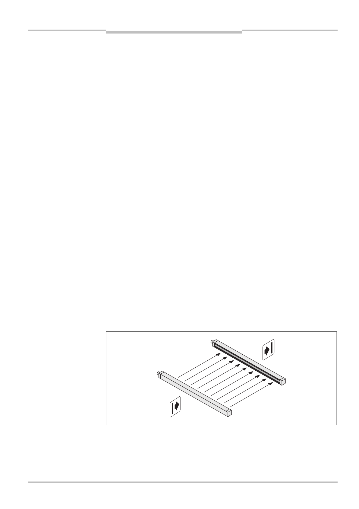
Fig.
1
:
Components of the
C4000 Entry/Exit
Sender
Receiver
Chapter 3Operating Instructions
C4000 Entry/Exit
12 ©SICK AG • Industrial Safety Systems • Germany • All rights reserved 8 010 241/NA55/23-10-03
Product description
3.2.2 The light curtain principle
The safety light curtain C 4000 consists of a sender and a receiver (Fig. 1). Between these
two units is the protective field, defined as the protective field length and the protective
field width.
The construction height determines the protective field length of the appropriate system.
For the exact protective field length, please see Tab. 22ff. in chapter 11.4 “Dimensional
drawings” on page 55.
The protective field width is derived from the dimension of the light path between sender
and receiver and must not exceed the maximum rated protective field width (see “Techni-
cal specifications” on page 49).
Sender and receiver automatically synchronise themselves optically. An electrical connec-
tion between both components is not required.
The C 4000 is modular in structure. All optical and electronic components and assemblies
are housed in a slim and torsionally rigid housing.
3.3 Examples of range of use
The safety light curtain C 4000 operates correctly as a protective device only if the follow-
ing conditions are met:
The control of the machine must be electrical.
It must be possible to achieve a safe state on the machine at any time.
Sender and receiver unit must be so mounted that objects penetrating the hazardous
area are safely identified by the C 4000.
The restart button must be fitted outside the hazardous area such that it cannot be
operated by a person working inside the hazardous area. When operating the reset
button, the operator must have full visual command of the hazardous area.
The statutory and local rules and regulations must be observed when installing and
using the device.
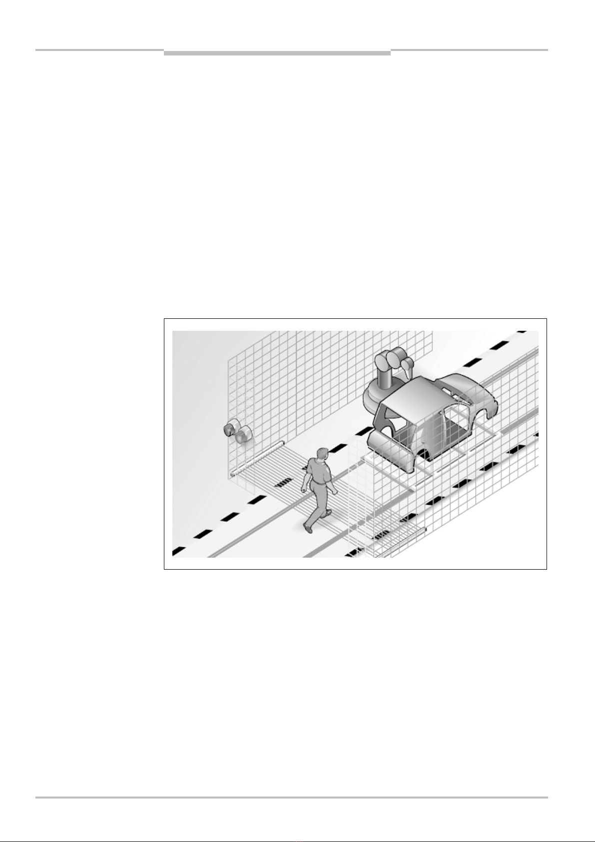
Fig.
2
:
Access protection with
self-teach dynamic blanking
Operating Instructions Chapter 3
C4000 Entry/Exit
8010 241/NA55/23-10-03 © SICK AG • Industrial Safety Systems • Germany • All rights reserved 13
Product description
3.4 Status indicators
The LEDs and the 7-segment displays of the sender and the receiver signal the operating
status of the C 4000.
The depiction of numbers on the 7-segment display can be rotated by 180° with the aid of
the CDS (Configuration & Diagnostic Software). If you rotate the numbers of the 7-segment
display, the point on the 7-segment display goes out:
Point visible: The bottom edge of the numbers on the 7-segment display is pointing
towards the configuration connection.
Point not visible: The bottom edge of the numbers on the 7-segment display is pointing
towards the LED display.
Device symbol C4000 Entry/Exit (receiver) or C4000 Entry/Exit (sender),context menu
Configuration draft,Edit,option 7-segment display of the related device.
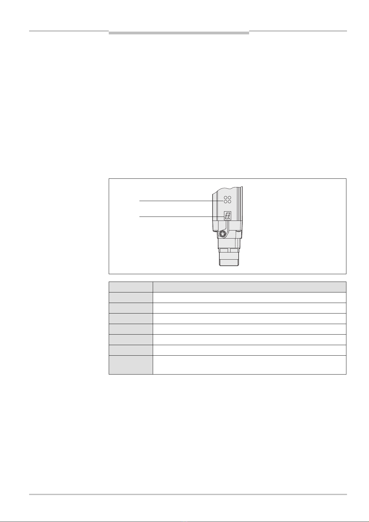
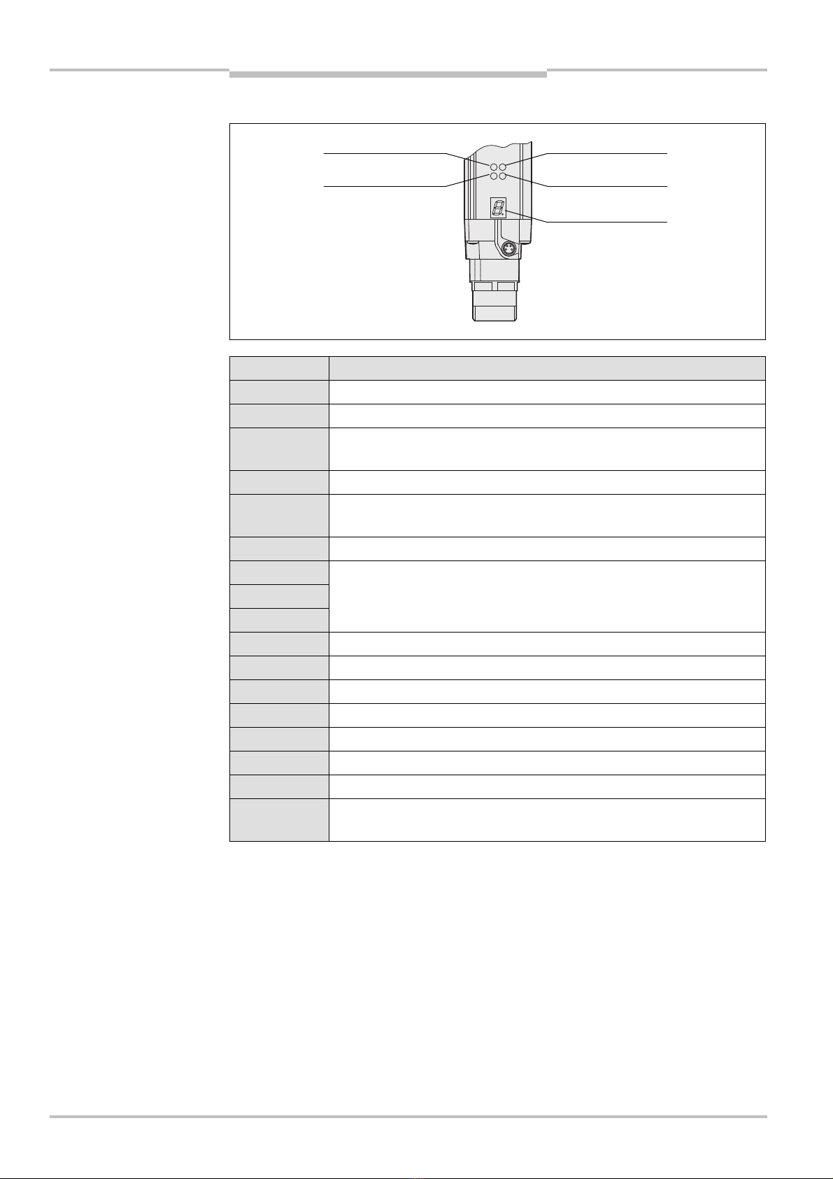
3.4.1 Status indicators of the sender
Display Meaning
Yellow Power supply OK
System error. The device is defective. Replace the sender.
The device is in the test mode.
Non-coded operation (only after switching on)
Operation with code 1 (only after switching on)
Operation with code 2 (only after switching on)
Other displays All other displays are error messages. Please refer to chapter “Fault
diagnosis” on page 45.
Note
Fig.
3
:
Status indicators o
f
the sender
Tab.
1
:
Status indicators of
the sender
Yellow
7-segment display
Chapter 3Operating Instructions
C4000 Entry/Exit
14 ©SICK AG • Industrial Safety Systems • Germany • All rights reserved 8 010 241/NA55/23-10-03
Product description
3.4.2 Status indicators of the receiver
Display Meaning
Orange Cleaning or realignment required
Yellow Reset required
Red System providing signals for shutting down the machine (output signal
switching devices off)
Green System enabled (output signal switching devices on)
Bypass active (only in conjunction with SICK switching amplifier, e.g.
UE 402.)
System error. The device is defective. Replace the receiver.
Poor alignment to sender.
Please refer to chapter 7.2 “Aligning sender and receiver” on page 40.
Operation with large protective field width (only after switching on)
Self-teach dynamic blanking active
Object in the protective field with activated self-teach dynamic blanking
Non-coded operation (only after switching on)
Operation with code 1 (only after switching on)
Operation with code 2 (only after switching on)
Emergency stop active
Other displays All other displays are error messages. Please refer to chapter “Fault
diagnosis” on page 45.
Fig.
4
:
Status indicators of
the receiver
Tab.
2
:
Status indicators of
the receiver
Orange
Yellow
Red
Green
7-segment display

Operating Instructions Chapter 4
C4000 Entry/Exit
8010 241/NA55/23-10-03 © SICK AG • Industrial Safety Systems • Germany • All rights reserved 15
Configurable functions
4Configurable functions
This chapter describes the functions of the safety light curtain C 4000 Entry/Exit which are
selectable via software.
Test the protective device after any changes!
The entire protective device must be tested for correct operation after each change of the
configuration (see chapter 7.3 “Test notes” on page 41).
When starting to configure the device, you may save an application name with a maximum
of 22 characters. Use this function as a “memory jog”, e.g. to describe the application of
the current device configuration. Device symbol C4000 Entry/Exit (receiver) or C4000
Entry/Exit (sender),context menu Configuration draft,Edit,file card General,option
Application name.
4.1 Restart interlock
Always configure the application with restart interlock!
Ensure that there is always a restart interlock. The C 4000 is unable to verify if the restart
interlock of the machine is operable. If you deactivate both the internal and the machine’s
restart interlock, the operators of the machine will be at an acute risk of injury.
The dangerous state of the machine is interrupted if the light path is broken, and is not re-
enabled until the operator presses the reset button.
Do not confuse the restart interlock with the starting interlock on the machine. The start
interlock prevents the machine starting after switching on. The restart interlock prevents
the machine starting again after an error or an interruption in the light path.
The possible combinations are shown in the following table:
Restart interlock of
the C 4000
Restart interlock of
the machine
Permissible
application
Deactivated Activated All
Activated Activated All. Restart interlock of the C 4000 handles
the reset function (see “Reset” below).
Activated Deactivated Not permitted
Deactivated Deactivated Not permitted
The electrical connection of the reset button is described in chapter “Reset button” on
page 37.
Device symbol C4000 Entry/Exit (receiver),context menu Configuration draft,Edit,file
card General,option Restart interlock.
You can indicate the status Reset required using a signal lamp. The C 4000 has a dedi-
cated output for this purpose. The electrical connection of the signal lamp is described in
chapter “Connection of a signal lamp to the output Reset required”on page 37.
WARNING
WARNING
Note
Tab.
3
:
Permissible
configuration of the restart
interlock
Recommendation

Chapter 4Operating Instructions
C4000 Entry/Exit
16 ©SICK AG • Industrial Safety Systems • Germany • All rights reserved 8 010 241/NA55/23-10-03
Configurable functions
Reset
If you want to activate the restart interlock on the C 4000 (internal) and also a restart inter-
lock on the machine (external), then each restart interlock has its own button.
When actuating the reset button for the internal restart interlock …
the C 4000 activates the output signal switching devices.
the safety light curtain changes from red to green.
Only the external restart interlock prevents the machine from restarting. After pressing the
reset button for the C 4000, the operator must also press the restart button for the ma-
chine. If the reset button and the restart button are not pressed in the specified sequence,
the dangerous state remains disrupted.
The reset button prevents the accidental and inadvertent operation of the external restart
button. The operator must first acknowledge the dangerous state with the reset button.
4.2 External device monitoring (EDM)
The external device monitoring (EDM) checks if the contactors actually de-energise when
the protective device responds. If you activate external device monitoring, then the C 4000
checks the contactors after each interruption to the light path and prior to machine restart.
The EDM can so identify if one of the contacts has fused, for instance. In this case …
the error message appears in the 7-segment display.
the safety light curtain remains red.
with the internal restart interlock activated, the safety light curtain uses the flashing
LED Yellow to signal “Reset required”.
If the system is unable to change to a safe operational state (e.g. after contactor failure),
the system locks and shuts down completely (lock-out). The 7-segment display will then
show the error message .
The electrical connection for the external device monitoring is described in chapter 6.4
“External device monitoring (EDM)” on page 36.
Device symbol C4000 Entry/Exit (receiver),context menu Configuration draft,Edit,file
card General,option EDM.
4.3 Emergency stop
The C 4000 has an input for a two-channel emergency stop button. The emergency stop
monitoring in the device corresponds to stop category 0 in accordance with EN 418. You
can connect e.g. a door contact or an emergency stop button to the emergency stop input.
The operation of the emergency stop button has the following effect:
The safety light curtain deactivates the OSSDs.
The C 4000 Entry/Exit switches to red.
The 7-segment display on the C 4000 Entry/Exit indicates .
The emergency stop function deactivates the OSSDs even if the bypass function is acti-
vated.
Take into account the response time of the emergency stop function! The response time of
the safety light curtain on interruption via the emergency stop input is up to 200 ms.
Pay attention to the way in which the emergency stop function works!
The emergency stop button connected to the extension connection on the C 4000 affects
only the output signal switching devices (OSSDs) on the C 4000.
Recommendation
Note
Notes
WARNING

Operating Instructions Chapter 4
C4000 Entry/Exit
8010 241/NA55/23-10-03 © SICK AG • Industrial Safety Systems • Germany • All rights reserved 17
Configurable functions
The C 4000 checks after switch on whether an emergency stop function has been confi-
gured and whether a door switch or similar switch is connected. If the configuration and
the electrical connection do not match, the system locks completely (lock-out). The 7-seg-
ment display will then show the error message .
The safety light curtain has a signal output (ADO) at which the status of the emergency
stop input can be signalled. For details refer to the next section.
Regularly check the connected emergency stop button or door contact!
By means of organisational measures ensure that the emergency stop button or door
contact is operated once at a specified interval.
This is necessary so that the C 4000 can detect any fault that has occurred on the emer-
gency stop button or door switch. The interval is to be defined to suit the specific case
dependant on the application.
Always check whether the output signal switching devices on the light curtain are deacti-
vated on the operation of the emergency stop button or door switch.
The electrical connection of the emergency stop is described in chapter 6.6 “Emergency
stop” on page 38.
Device symbol C4000 Entry/Exit (receiver),context menu Configuration draft,Edit,file
card General,option Emergency stop active.
4.4 Signal output (AD )
The C 4000 has a signal output (ADO) that can be configured. With the aid of the signal
output, the safety light curtain can signal specific states. You can use this output for a
relay or a FPLC.
You must not use the signal output for safety-relevant functions!
You are only allowed to use the signal output for signalling. You must never use the signal
output for controlling the application or with safety-relevant functions.
The connection can signal one of the following states:
Assignment Possible uses
Contamination Eases diagnostics in case of contaminated front screen.
OSSD status with
delay of [s]
Signals the status of the output signal switching devices. If the
safety light curtain switches to red, then it signals the status
immediately. If it switches to green, then it signals the status only
after an adjustable delay in the range from 0.1 to 3.1 seconds.
Status of the
emergency stop
Signal is present if the button connected to the emergency stop
input on the C 4000 has been pressed.
Device symbol C4000 Entry/Exit (receiver),context menu Configuration draft,Edit,file
card General,option Assignment of the signal output.
The electrical connection of a PLC/controller to the signal output is described in chap-
ter 6.7 “Signal output (ADO)” on page 39.
Notes
WARNING
WARNING
Tab.
4
:
Possible
configuration for the signal
output

Chapter 4Operating Instructions
C4000 Entry/Exit
18 ©SICK AG • Industrial Safety Systems • Germany • All rights reserved 8 010 241/NA55/23-10-03
Configurable functions
4.5 Beam coding
If several safety light curtains operate in close proximity to each other, the sender beams
of one system may interfere with the receiver of another system. With code 1 or 2 activa-
ted, the receiver can distinguish the beams designated for it from other beams. The follow-
ing settings are available: non-coded, code 1 and code 2.
Use different beam codings if the systems are mounted in close proximity!
Systems mounted in close proximity to each other must be operated with different beam
codings (code 1 or code 2). If this precaution is neglected, the system may be impaired in
its protective function by the beams from the neighbouring system and so change to the
unsafe state. This would mean that the operator is at risk.
Beam coding increases the availability of the protected machine. Beam coding also
enhances the resistance to optical interference such as weld sparks or similar.
Beam coding will increase the response time of the system. This may also change the
required safety distance. Instructions can be found in chapter 5.1 “Determining the
safety distance” on page 24.
After activating the system, sender and receiver will briefly display the coding.
Device symbol C4000 Entry/Exit (receiver) or C4000 Entry/Exit (sender),context menu
Configuration draft,Edit,file card General,option Beam coding.
4.6 Scanning range
Match the scanning range with the protective field width!
The scanning range of the system must be adapted to the protective field width.
If the scanning range is set too low, the light curtain may not switch to green.
If the scanning range is too great, the light curtain may malfunction. This would mean
that the operator is at risk.
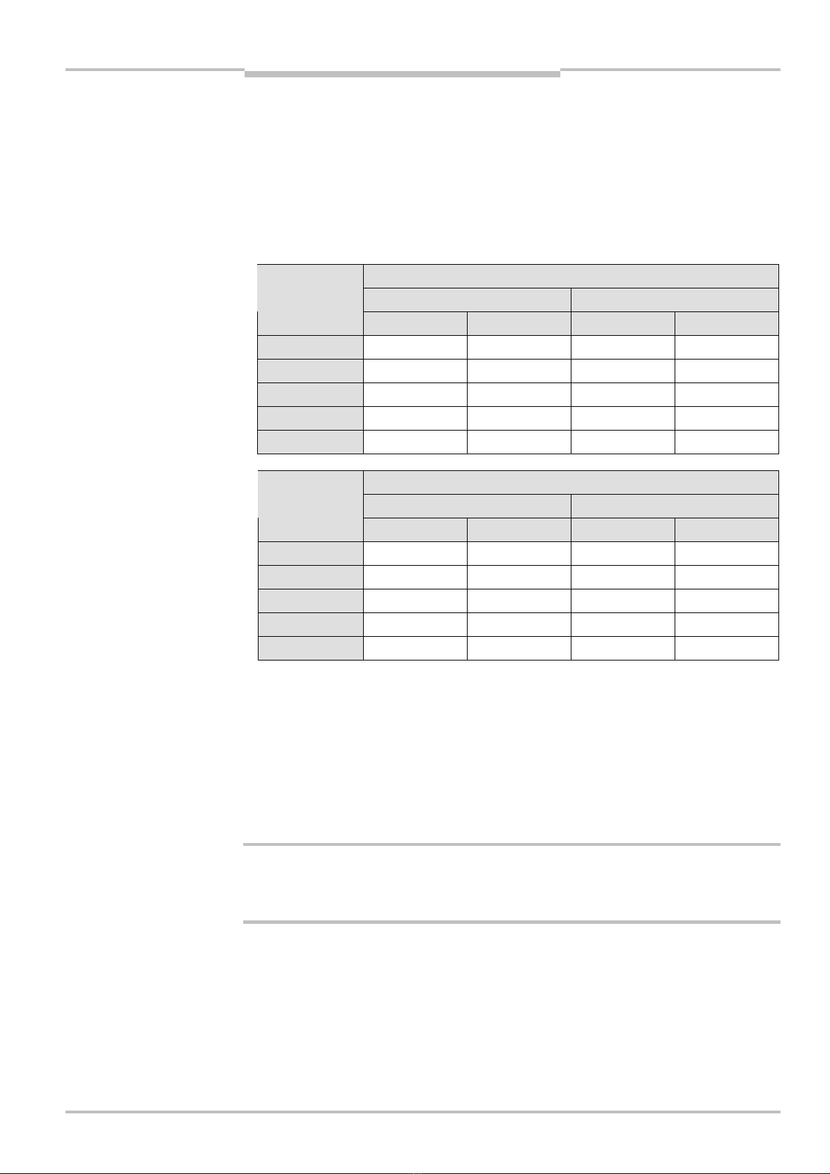
The available settings depend on the physical resolution of the system:
Physical resolution Selectable
scanning ranges
Scanning range with
1additional front screen
Scanning range with
2additional front screens
14 mm 0.5–2.5 m
2–6 m
0.5–2.3 m
1.8–5.5 m
0.5–2.1 m
1.7–5 m
20 mm, 30 mm,
40 mm
0.5–6 m
5–19 m
0.5–5.5 m
4.6–17.4 m
0.5–5 m
4.2–16 m
Device symbol C4000 Entry/Exit (receiver),context menu Configuration draft,Edit,file
card Standalone,option Scanning range [m].
WARNING
Fig.
5
:
Schematic layout of
the beam coding
Notes
WARNING
Tab.
5
:
Physical resolution
and scanning range
Code 1
Code 2
Operating Instructions Chapter 4
C4000 Entry/Exit
8010 241/NA55/23-10-03 © SICK AG • Industrial Safety Systems • Germany • All rights reserved 19
Configurable functions
If you are using the additional front screen (see page 60) available as an accessory, the
overall scanning range will be reduced by 8%for each additional front screen.
The deflector mirrors available as accessories (see page 58f.) reduce the overall scan-
ning range as a function of the number of deflector mirrors in the light path (see Tab. 6
for PNS 75 and Tab. 7 for PNS 125). When using deflector mirrors, you must configure
the light curtain for a long scanning range.
The usage of deflector mirrors is not allowed if the formation of droplets or heavy con-
tamination of the deflector mirrors is to be expected.
Scanning range for physical resolution/number of deflector mirrors
14 mm 20, 30 or 40 mm
Protective field
length [mm]
1 × PNS 75 2 × PNS 75 1 × PNS 75 2 × PNS 75
900 4.8 m 3.3 m 7.4 m 8.0 m
1050 4.8 m 3.2 m 6.8 m 7.5 m
1200 4.8 m 2.9 m 6.4 m 7.1 m
1350 4.8 m 2.6 m 6.0 m 6.6 m
1500 4.6 m 2.3 m 5.8 m 6.3 m
Scanning range for physical resolution/number of deflector mirrors
14 mm 20, 30 or 40 mm
Protective field
length [mm]
1 × PNS 125 2 × PNS 125 1 × PNS 125 2 × PNS 125
900 4.8 m 3.8 m 14.2 m 12.3 m
1050 4.8 m 3.8 m 13.6 m 12.3 m
1200 4.8 m 3.6 m 13.0 m 12.3 m
1350 4.8 m 3.5 m 12.6 m 12.3 m
1500 4.8 m 3.3 m 12.0 m 12.3 m
4.7 Multiple sampling
When multiple sampling is set, the C 4000 Entry/Exit must detect an object several times,
before it deactivates its OSSDs. In this way you can reduce the probability that objects
falling through the protective field, for example welding sparks or other particles, result in
the shutdown of the plant.
With a multiple sampling configuration of, e.g., 3, the C 4000 Entry/Exit must detect an
object three times in succession before it switches off the OSSDs.
Check the total response time!
The total response time is increased by the multiple sampling! If you change the multiple
sampling, then you must recalculate the response time (see Tab. 19 on page 53).
On the C 4000 Entry/Exit, a multiple sampling of 2 is the default setting. You can set the
multiple sampling to up to 3 with the aid of the CDS.
Device symbol C4000 Entry/Exit (receiver),context menu Configuration draft,Edit,
selection System,file card Standalone,option Multiple sampling.
Notes
Tab.
6
:
Scanning range when
using 1 or 2 PNS 75 deflector
mirrors
Tab.
7
:
Scanning range when
using 1 or 2 PNS 125
deflector mirrors
WARNING
Note
Chapter 4Operating Instructions
C4000 Entry/Exit
20 ©SICK AG • Industrial Safety Systems • Germany • All rights reserved 8 010 241/NA55/23-10-03
Configurable functions
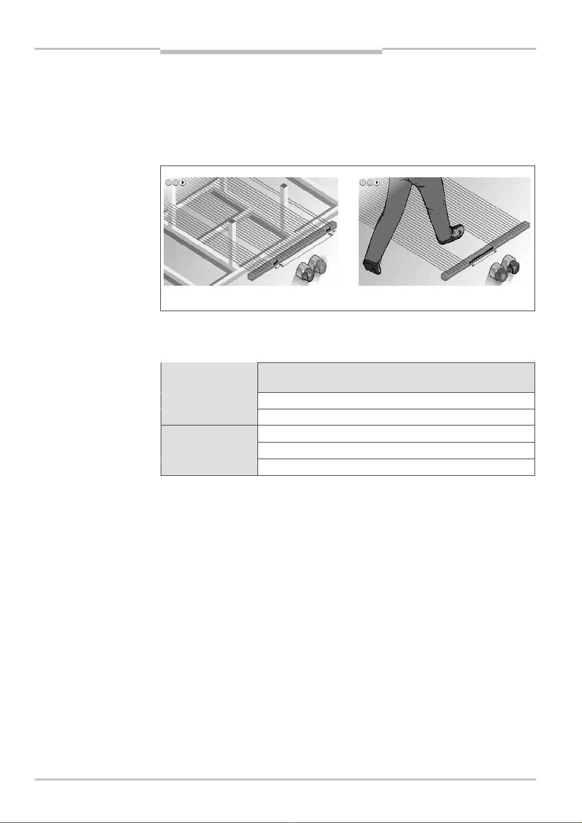
4.8 Self-teach dynamic blanking
On the C 4000 Entry/Exit you configure the self-teach dynamic blanking.
The self-teching dynamic blanking provides access protection in which precisely defined
objects (e.g. transport trolleys for car body shells) have access to a system or machine (see
Fig. 6, ). However, if other objects, particularly people, enter the protective field, the
C4000 shuts down the output signal switching devices (see Fig. 6, ).
The self-teach dynamic blanking enables several objects in the beam path to be blanked
dynamically, depending on the protective field length (see Tab. 8). In addition, these
objects are allowed to move in both directions.
Protective field length
[mm]
Maximum number of dynamic blanked objects
900 3
1050 4
1200 4
1350 5
1500 5
If you configure e.g. three objects which are allowed to be blanked dynamically, transport
trolleys with one, two or three legs or transport trolleys with one, two or three pairs of
aligned legs can be used.
On light curtains with a resolution of 30 or 40 mm only one object is allowed!
Device symbol C4000 Entry/Exit (receiver),context menu Configuration draft,Edit,file
card Self-teach dynamic blanking,option Maximum number of floating objects.
While the object passes through the protective field, the C 4000 monitors the speed at
which the object moves. This must not exceed 2 m/s.
The objects must enter the beam path of the C 4000 from the same direction. During this
process the C 4000 first dynamically teaches itself the distance between the objects. The
C4000 monitors this distance until the objects leave the beam path.
Fig.
6
:
Schematic diagram of
the self-teach dynamic
blanking
Tab.
8
:
Maximum number of
dynamic blanked objects,
depending on the protective
field length
Note
Other manuals for C 4000
2
Table of contents
Other SICK Lighting Equipment manuals

SICK
SICK deTec4 Core User manual

SICK
SICK deTec4 Core User manual

SICK
SICK C4-RD User manual

SICK
SICK C 4000 User manual

SICK
SICK C4000 Select User manual

SICK
SICK deTec4 Core User manual

SICK
SICK deTem4 Core Ex User manual

SICK
SICK deTec4 Core User manual

SICK
SICK C 4000 Series User manual

SICK
SICK deTec2 Core User manual


Popular Lighting Equipment manuals by other brands

Robus
Robus VEGAS Series quick start guide

Zhiyun
Zhiyun FIVERAY V60 user guide

Pro Audio Trade
Pro Audio Trade nono light RGB LASER DMX 3000 user manual

SLV Elektronik
SLV Elektronik 160331 instruction manual

Bathology
Bathology Spectrum 440 Installation and operation manual

Soltech
Soltech NUVO quick start guide


