SICK C 4000 User manual

C 4000 Standard/Advanced
Safety Light Curtain
OPERATING INSTRUCTIONS
&

Operating Instructions
C 4000 Standard/Advanced
2© SICK AG • Industrial Safety Systems • Germany • All rights reserved 8 009 861/OE59/19-11-04
This document is protected by the law of copyright, whereby all rights established therein remain with the com-
pany SICK AG. Reproduction of this document or parts of this document is only permissible within the limits of the
legal determination of Copyright Law. Alteration or abridgement of the document is not permitted without the
explicit written approval of the company SICK AG.

Operating Instructions
C 4000 Standard/Advanced
8 009 861/OE59/19-11-04 © SICK AG • Industrial Safety Systems • Germany • All rights reserved 3
List of contents
List of contents
1 About this document....................................................................................................................... 6
1.1 Function of this document ........................................................................................6
1.2 Target group...............................................................................................................6
1.3 Scope .........................................................................................................................6
1.4 Depth of information .................................................................................................6
1.5 Abbreviations .............................................................................................................7
1.6 Symbols used.............................................................................................................7
2 On safety............................................................................................................................................. 9
2.1 Specialist personnel..................................................................................................9
2.2 Applications of the device.........................................................................................9
2.3 Correct use.............................................................................................................. 10
2.4 General protective notes and protective measures ............................................. 10
2.5 Protection of the environment ............................................................................... 11
3 Product description .......................................................................................................................12
3.1 Special features...................................................................................................... 12
3.2 Operating principle of the device........................................................................... 14
3.2.1 Components of the device......................................................................... 14
3.2.2 The light curtain principle .......................................................................... 14
3.2.3 Cascading ................................................................................................... 14
3.3 Examples of range of use....................................................................................... 15
3.4 Status indicators..................................................................................................... 16
3.4.1 Status indicators of the sender................................................................. 16
3.4.2 Status indicators of the receiver ............................................................... 17
4 Configurable functions .................................................................................................................18
4.1 Restart interlock ..................................................................................................... 18
4.2 External device monitoring (EDM) ......................................................................... 20
4.3 Emergency stop ...................................................................................................... 21
4.4 Bypass..................................................................................................................... 22
4.5 Output signal (ADO) ................................................................................................ 22
4.6 Beam coding........................................................................................................... 23
4.7 Scanning range....................................................................................................... 24
4.8 Blanking .................................................................................................................. 25
4.8.1 Fixed blanking ............................................................................................ 27
4.8.2 Floating blanking........................................................................................ 29
4.8.3 Effective resolution for blanking................................................................ 31
4.8.4 Teach-in of blanked areas ......................................................................... 32
4.9 Reduced resolution ................................................................................................ 34
4.10 Sender test.............................................................................................................. 35
4.11 Functions that cannot be combined...................................................................... 36
5 Installation and mounting............................................................................................................37
5.1 Determining the safety distance............................................................................ 37
5.1.1 Safety distance from the hazardous point................................................ 37
5.1.2 Minimum distance to reflective surfaces ................................................. 40
5.2 Steps for mounting the device............................................................................... 41
5.2.1 Mounting with swivel mount bracket ........................................................ 42
5.2.2 Mounting with side bracket ....................................................................... 44

Operating Instructions
C 4000 Standard/Advanced
4© SICK AG • Industrial Safety Systems • Germany • All rights reserved 8 009 861/OE59/19-11-04
List of contents
6 Electrical installation ....................................................................................................................46
6.1 System connection M26)×)11 + FE......................................................................... 47
6.2 Configuration connection M8)×)4 (serial interface)................................................48
6.3 Extension connection M26)×)11 + FE..................................................................... 49
6.4 External device monitoring (EDM)..........................................................................50
6.5 Reset button............................................................................................................ 51
6.6 Teach-in key-operated switch .................................................................................52
6.7 Emergency stop....................................................................................................... 53
6.8 Key-operated switch for bypass .............................................................................54
6.9 Output signal (ADO).................................................................................................54
6.10 Test input (sender test)........................................................................................... 55
6.11 Intelliface applications............................................................................................ 55
7 Commissioning................................................................................................................................56
7.1 Display sequence during power-up ........................................................................ 56
7.2 Aligning sender and receiver.................................................................................. 56
7.3 Test notes................................................................................................................ 57
7.3.1 Tests before the first commissioning ........................................................57
7.3.2 Regular inspection of the protective device by qualified personnel........57
7.3.3 Daily functional checks of the protective device ...................................... 58
8 Configuration ...................................................................................................................................59
8.1 Delivery status.........................................................................................................59
8.2 Preparing the configuration....................................................................................59
9 Care and maintenance..................................................................................................................60
10 Fault diagnosis................................................................................................................................61
10.1 What to do in case of faults.................................................................................... 61
10.2 SICK Support ...........................................................................................................61
10.3 Error displays of the diagnostics LEDs...................................................................61
10.4 Error displays of the 7-segment display................................................................. 62
10.5 Status indicators on the C 4000............................................................................64
10.6 Extended diagnosis.................................................................................................65
11 Technical specifications ..............................................................................................................66
11.1 Data sheet ............................................................................................................... 66
11.2 Response time ........................................................................................................69
11.3 Table of weights ...................................................................................................... 72
11.3.1 C 4000 Standard/Advanced...................................................................... 72
11.3.2 Deflector mirrors PNS 75 and PNS 125.................................................... 72
11.4 Dimensional drawings ............................................................................................73
11.4.1 C 4000 Standard/Advanced without extension connection....................73
11.4.2 C 4000 Standard with angled system connection and without
extension connection .................................................................................74
11.4.3 C 4000 Standard/Advanced with extension connection .........................75
11.4.4 Swivel mount bracket.................................................................................76
11.4.5 Side bracket................................................................................................ 76
11.4.6 Deflector mirror PNS 75............................................................................. 77
11.4.7 Deflector mirror PNS 125...........................................................................78

Operating Instructions
C 4000 Standard/Advanced
8 009 861/OE59/19-11-04 © SICK AG • Industrial Safety Systems • Germany • All rights reserved 5
List of contents
12 Ordering information .....................................................................................................................79
12.1 Delivery....................................................................................................................79
12.2 System without extension connection................................................................... 80
12.2.1 C 4000 Standard without extension connection...................................... 80
12.2.2 C 4000 Standard with angled system connection and without
extension connection................................................................................. 81
12.2.3 C 4000 Advanced without extension connection..................................... 81
12.2.4 C 4000 Standard without extension connection with
pre-configuration C..................................................................................... 82
12.2.5 C 4000 Standard without extension connection with
pre-configuration D..................................................................................... 83
12.2.6 C 4000 Standard without extension connection with
pre-configuration E..................................................................................... 84
12.2.7 C 4000 Standard without extension connection with
pre-configuration F ..................................................................................... 85
12.3 System with extension connection ........................................................................ 86
12.3.1 C 4000 Standard with extension connection........................................... 86
12.3.2 C 4000 Advanced with extension connection.......................................... 87
12.4 Additional front screen (weld spark guard) ........................................................... 88
12.5 Deflector mirror....................................................................................................... 88
12.5.1 Deflector mirror PNS 75 for protective field width 0 … 8 m (total).......... 88
12.5.2 Deflector mirror PNS 125 for protective field width 4 … 17 m
(total)........................................................................................................... 89
12.6 Accessories ............................................................................................................. 89
13 Annex .................................................................................................................................................91
13.1 Declaration of conformity....................................................................................... 91
13.2 Checklist for the manufacturer.............................................................................. 92
13.3 List of tables ........................................................................................................... 93
13.4 List of illustrations .................................................................................................. 94

Chapter 1Operating Instructions
C 4000 Standard/Advanced
6© SICK AG • Industrial Safety Systems • Germany • All rights reserved 8 009 861/OE59/19-11-04
About this document
1About this document
Please read this chapter carefully before working with this documentation and the C 4000.
1.1 Function of this document
These operating instructions are designed to address the technical personnel of the
machine manufacturer or the machine operator in regards to safe mounting, installation,
configuration, electrical installation, commissioning, operation and maintenance of the
safety light curtain C 4000.
These operating instructions do not provide instructions for operating machines on which
the safety light curtain is, or will be, integrated. Information on this is to be found in the
appropriate operating instructions of the machine.
1.2 Target group
These operating instructions are addressed to planning engineers, developers and the
operators of plants and systems which are to be protected by one or several safety light
curtains C 4000. It also addresses persons who integrate the C 4000 into a machine,
initialise its use, or who are in charge of servicing and maintaining the unit.
1.3 Scope
These operating instructions apply to the safety light curtain C 4000 Standard and C 4000
Advanced with the following entry on the type label in the field Operating Instructions:
8 009 855/OE59. This document is part of SICK part number 8 009 855/OE59 (operating
instructions “C 4000 Safety Light Curtain” in all available languages).
For the configuration and diagnostics of these devices you require CDS (Configuration &
Diagnostic Software) version 2.10 or higher. To determine the version of your software
version, select the Module-Info... option in the ?menu.
1.4 Depth of information
These operating instructions contain information on:
$installation and mounting
$electrical installation
$commissioning and configuration
$care and maintenance
$fault, error diagnosis and
troubleshooting
$part numbers
$conformity and approval
of the safety light curtain C 4000.
Planning and using protective devices such as the C 4000 also require specific technical
skills which are not detailed in this documentation.
When operating the C 4000, the national, local and statutory rules and regulations must
be observed.
General information on health and safety at work and accident prevention using opto-elec-
tronic protective devices can be found in the brochure “Safe Machines with opto-electronic
protective devices”.
Note

Operating Instructions Chapter 1
C 4000 Standard/Advanced
8 009 861/OE59/19-11-04 © SICK AG • Industrial Safety Systems • Germany • All rights reserved 7
About this document
We also refer you to the SICK homepage on the Internet at
www.sick.com
Here you will find information on:
$sample applications
$a list of frequently asked questions about the C 4000
$these operating instructions in different languages for viewing and printing
$certificates on the prototype test, the EC declaration of conformity and other documents
1.5 Abbreviations
Application diagnostic output = configurable output signal that indicates a specific status
of the protective device
Electro-sensitive protective equipment (e.g. C 4000)
SICK Configuration & Diagnostic Software
External device monitoring
Enhanced function interface = safe SICK device communication
Output signal switching device
1.6 Symbols used
Recommendations are designed to give you some assistance in your decision-making
process with respect to a certain function or a technical measure.
Refer to notes for special features of the device.
Display indicators show the status of the 7-segment display of sender or receiver:
BConstant indication of characters, e.g. U
Flashing indication of characters, e.g. 8
;O) Alternating indication of characters, e.g. L and 2
The depiction of numbers on the 7-segment display can be rotated by 180° with the aid of
the CDS. In this document the depiction of the numbers on the 7-segment display is how-
ever always in the normal, non-rotated position.
LED symbols describe the state of a diagnostics LED. Examples:
,Red The red LED is illuminated constantly.
+Yellow The yellow LED is flashing.
-Green The green LED is off.
Instructions for taking action are shown by an arrow. Read carefully and follow the instruc-
tions for action.
Warning!
A warning indicates an actual or potential risk or health hazard. They are designed to help
you to prevent accidents.
Read carefully and follow the warnings!
Note
ADO
ESPE
CDS
EDM
EFI
OSSD
Recommendation
Note
, ;O)
,Red, +Yellow,
-Green
Take action …
%
WARNING

Chapter 1Operating Instructions
C 4000 Standard/Advanced
8© SICK AG • Industrial Safety Systems • Germany • All rights reserved 8 009 861/OE59/19-11-04
About this document
Software notes show the location in the CDS (Configuration & Diagnostic Software) where
you can make the appropriate settings and adjustments. Go to the menu View, Dialog box
of the CDS and activate the item File cards to view the named dialog fields as required.
Alternatively, the Software Assistant will guide you through the appropriate setting.
If you use the SICK switching amplifier UE 402, you will find the functions under the same
names, however to some extent in different places in the CDS Configuration dialog box.
This is dependent on the scope of the related function. The operating instructions for the
UE 402 contain detailed information.
Sender and receiver
In drawings and diagrams, the symbol #denotes the sender and the symbol "denotes
the receiver.
The term “dangerous state”
The dangerous state (standard term) of the machine is always shown in the drawings and
diagrams of this document as the movement of a machine part. In practical operation,
there may be a number of different dangerous states:
$machine movements
$electrical conductors
$visible or invisible radiation
$a combination of several risks and hazards
!
#"

Operating Instructions Chapter 2
C 4000 Standard/Advanced
8 009 861/OE59/19-11-04 © SICK AG • Industrial Safety Systems • Germany • All rights reserved 9
On safety
2On safety
This chapter deals with your own safety and the safety of the equipment operators.
Please read this chapter carefully before working with the C 4000 or with the machine
protected by the C 4000.
2.1 Specialist personnel
The safety light curtain C 4000 must be installed, commissioned and serviced only by
specialist personnel. Specialist personnel are defined as persons who
$have undergone the appropriate technical training
and
$who have been instructed by the responsible machine operator in the operation of the
machine and the current valid safety guidelines
and
$who have access to these operating instructions.
2.2 Applications of the device
The safety light curtain C 4000 is an item of electro-sensitive protective equipment (ESPE).
The physical resolution is 14, 20, 30 or 40 mm with a maximum protective field width of
19 metres (resolution 20 mm and higher). The realisable protective field height is between
300 and 1,800 mm.
The device is a Type 4 ESPE as defined by IEC 61)496-1 and -2 and is therefore allowed for
use with controls in control category 4 in compliance with EN 954-1. The emergency stop
monitoring in the device corresponds to stop category 0 in accordance with EN 418. The
device is suitable for:
$hazardous point protection (finger and hand protection)
$hazardous area protection
$access protection
Access to the hazardous point must be allowed only through the protective field. The
plant/system is not allowed to start as long as personnel are within the hazardous area.
Refer to chapter 3.3 “Examples of range of use” on page 15 for an illustration of the
protection modes.
Only use the safety light curtain as an indirect protective measure!
An opto-electronic protective device provides indirect protection, e.g., by switching off the
power at the source of the hazard. It cannot provide protection from parts thrown out, nor
from emitted radiation. Transparent objects are not detected.
Depending on the application, mechanical protection devices may be required in addition
to the safety light curtain.
The safety light curtain C 4000 operates as a standalone system, comprising a sender and
receiver, or in combination with other cascadable C 4000 systems. This means that the
protective field can be adapted to suit individual safety requirements.
%
WARNING
Note

Chapter 2Operating Instructions
C 4000 Standard/Advanced
10 © SICK AG • Industrial Safety Systems • Germany • All rights reserved 8 009 861/OE59/19-11-04
On safety
2.3 Correct use
The safety light curtain C 4000 must be used only as defined in chapter 2.2 “Applications
of the device”. It must be used only by qualified personnel and only on the machine where
it has been installed and initialised by qualified personnel.
If the device is used for any other purposes or modified in any way-also during mounting
and installation-any warranty claim against SICK AG shall become void.
2.4 General protective notes and protective measures
Safety notes
Please observe the following procedures in order to ensure the correct and safe use of the
safety light curtain C 4000.
$The national/international rules and regulations apply to the installation, use and
periodic technical inspections of the safety light curtain, in particular:
–Machine Directive 98/37/EEC
–Equipment Usage Directive 89/655/EEC
–the work safety regulations/safety rules
–other relevant health and safety regulations
Manufacturers and operators of the machine with which the safety light curtain is used
are responsible for obtaining and observing all applicable safety regulations and rules.
$The notices, in particular the test regulations (see “Test notes” on page 57) of these
operating instructions (e.g. on use, mounting, installation or integration into the existing
machine controller) must be observed.
$Changes to the configuration of the devices can degrade the protective function. After
every change to the configuration you must therefore check the effectiveness of the
protective device.
The person who makes the change is also responsible for the correct protective function
of the device. When making configuration changes, please always use the password
hierarchy provided by SICK to ensure that only authorised persons make changes to the
configuration. The SICK service team is available to provide assistance if required.
$The tests must be carried out by specialist personnel or specially qualified and autho-
rised personnel and must be recorded and documented to ensure that the tests can be
reconstructed and retraced at any time.
$The operating instructions must be made available to the operator of the machine where
the safety light curtain C 4000 is fitted. The machine operator is to be instructed in the
use of the device by specialist personnel and must be instructed to read the operating
instructions.
$The external voltage supply of the device must be capable of buffering brief mains vol-
tage failures of 20 ms as specified in EN 60)204-1. Suitable power supplies are available
as accessories from SICK (Siemens type series 6 EP 1).
%
WARNING

Operating Instructions Chapter 2
C 4000 Standard/Advanced
8 009 861/OE59/19-11-04 © SICK AG • Industrial Safety Systems • Germany • All rights reserved 11
On safety
2.5 Protection of the environment
The safety light curtain C 4000 has been designed to minimise environmental impact. It
uses only a minimum of power and natural resources.
At work, always act in an environmentally responsible manner. For this reason please note
the following information on disposal.
Disposal
Always dispose of unserviceable or irreparable devices in compliance with local/national
rules and regulations with respect to waste disposal.
We would be pleased to be of assistance on the disposal of this device. Contact your local
SICK representative.
Note

Chapter 3Operating Instructions
C 4000 Standard/Advanced
12 © SICK AG • Industrial Safety Systems • Germany • All rights reserved 8 009 861/OE59/19-11-04
Product description
3Product description
This chapter provides information on the special features and properties of the safety light
curtain C 4000. It describes the construction and the operating principle of the device, in
particular the different operating modes.
Please read this chapter before mounting, installing and commissioning the device.
The descriptions of functions in this chapter only apply to the safety light curtain C 4000
Standard and C 4000 Advanced with the following entry on the type label in the field
Operating Instructions: 8 009 855/OE59.
3.1 Special features
C 4000 Standard
$protection with either internal or external (realised on the machine) restart interlock
$connection for the reset button either in the control cabinet or directly to the device
$connection option on device for an emergency stop button or a key-operated
switch for bypass
$external device monitoring (EDM)
$2 beam codings possible in addition to non-coded operation
$configurable output signal (ADO) for improved availability
$status display with 7-segment display
$range of functions can be expanded using switching amplifiers in the SICK Intelliface
product family
$EFI connection. Functional enhancement for C 4000 (with the type label entry in the
software field: 3.00 and greater) and switching amplifiers of the SICK Intelliface product
family
C 4000 Advanced
In addition to the features of the C 4000 Standard, the Advanced version offers:
$blanking of several areas
$blanking with tolerance of up to 2 beams
$floating blanking
$reduced resolution
$object monitoring for areas with floating blanking
$increased size tolerance for areas with fixed blanking
Note

Operating Instructions Chapter 3
C 4000 Standard/Advanced
8 009 861/OE59/19-11-04 © SICK AG • Industrial Safety Systems • Germany • All rights reserved 13
Product description
C 4000
Standard
C 4000
Advanced
Function that can be
configured
Without extension
connection
With extension
connection
Without extension
connection
With extension
connection
Special features
Emergency stop can be
connected to the device
Reset button can be
connected directly to the
device
Output for “Reset
required” on the device
= On devices without an
extension connection, these
functions can be accessed using
the terminal strip in the control
cabinet from the system
connection for the C 4000!
Output signal (ADO)
External device
monitoring (EDM)
Reduced resolution
Blanking
Teaching in blanked
areas
PSDI mode
Bypass
Operating mode
switching
= Only in conjunction with SICK
switching amplifier, e.g. UE 402
Tab. 1: Comparison of the
special features and con-
figurable functions of the
C 4000

Chapter 3Operating Instructions
C 4000 Standard/Advanced
14 © SICK AG • Industrial Safety Systems • Germany • All rights reserved 8 009 861/OE59/19-11-04
Product description
3.2 Operating principle of the device
3.2.1 Components of the device
Please refer to chapter 11 “Technical specifications” on page 66 for the data sheet.
Please refer to pages 73ff. for the dimensional drawings.
3.2.2 The light curtain principle
The safety light curtain C 4000 consists of a sender and a receiver (Fig. 1). Between these
two units is the protective field, defined as the protective field height and the protective
field width.
The construction height determines the height of the protective field of the appropriate
system. For the exact protective field height, please see Tab. 30)ff. in chapter 11.4
“Dimensional drawings” on page 73.
The width of the protective field is derived from the dimension of the light path between
sender and receiver and must not exceed the maximum rated width of the protective field
(see “Technical specifications” on page 66).
Sender and receiver automatically synchronise themselves optically. An electrical connec-
tion between both components is not required.
The C 4000 is modular in construction. All optical and electronic components and assemb-
lies are housed in a slim and torsionally rigid housing.
3.2.3 Cascading
To provide effective point-of-operation protection, a maximum of three C 4000 can be
connected in series as cascade.)The device connected to the control cabinet is the main
sensor, called Host. The subsequent sensors are called Guest (cf. Fig. 1 on page 14).
Benefits of cascading
$no additional external circuitry required
$resolution and protective field height may differ among the individual systems
Fig. 1: Components of the
C 4000
Host without extension
connection or — in case
g
ues
t
1 connected — with
extension connection
Optional: 1. Guest system
without extension
connection or — in case
g
ues
t
2 connected — with
extension connection
Optional: 2. Guest system
with or without extension
connection
Operating Instructions Chapter 3
C 4000 Standard/Advanced
8 009 861/OE59/19-11-04 © SICK AG • Industrial Safety Systems • Germany • All rights reserved 15
Product description
Limits of cascading
$The maximum protective field width must be guaranteed for each individual system!
$The maximum total number of beams must not exceed 480 beams in non-coded
operation, and a maximum of 405 beams in coded operation.
$The maximum cable length between two cascaded systems must not exceed 3 metres.
With the exception of the last guest, for cascading you will require devices with an exten-
sion connection. It is worthwhile choosing devices with an extension connection because
the extension connection provides additional possible connection methods and facilitates
a significant reduction in the wiring effort.
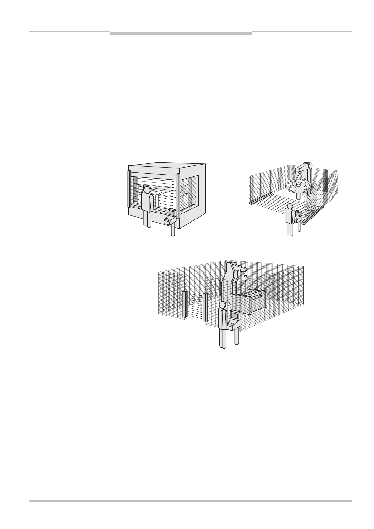
3.3 Examples of range of use
The safety light curtain C 4000 operates correctly as a protective device only if the follow-
ing conditions are met:
$The control of the machine must be electrical.
$The dangerous state of the machine must be transferable at any time into a safe state.
$Sender and receiver unit must be so mounted that objects penetrating the hazardous
area are safely identified by the C 4000.
$The restart button must be fitted outside the hazardous area such that it cannot be
operated by a person working inside the hazardous area. When operating the reset
button, the operator must have full visual command of the hazardous area.
$The statutory and local rules and regulations must be observed when installing and
using the device.
Recommendation
Fig. 2: Hazardous poin
t
protection using a safety light
curtain C 4000
(left)
Fig. 3: Hazardous area
protection using a safety light
curtain C 4000
(right)
Fig. 4:
A
ccess protection
using a safety light curtain
C 4000

Chapter 3Operating Instructions
C 4000 Standard/Advanced
16 © SICK AG • Industrial Safety Systems • Germany • All rights reserved 8 009 861/OE59/19-11-04
Product description
3.4 Status indicators
The LEDs and the 7-segment displays of the sender and the receiver signal the operational
status of the C 4000.
The depiction of numbers on the 7-segment display can be rotated by 180° with the aid of
the CDS (Configuration & Diagnostic Software). In this case the point on the 7-segment
display goes out:
$Point visible: The bottom edge of the numbers on the 7-segment display is pointing
towards the configuration connection.
$Point not visible: The bottom edge of the numbers on the 7-segment display is pointing
towards the LED display.
Device symbol C 4000 Host (receiver) or C 4000 Host (sender), context menu Configura-
tion draft, Edit, option 7-segment display of the related device.
3.4.1 Status indicators of the sender
Display Meaning
,Yellow Supply voltage OK
6System error. Disconnect the supply voltage to the C 4000 for at least
3 seconds. If the problem persists, replace the unit.
=The device is in the test mode.
BNon-coded operation (only after switching on)
%Operation with code 1 (only after switching on)
$Operation with code 2 (only after switching on)
Other
displays
All other displays are error messages. Please refer to chapter “Fault
diagnosis” on page 61.
Note
!
Fig. 5: Status indicators of
the sender
Tab. 2: Status indicators o
f
the sender
Yellow
7-segment display

Operating Instructions Chapter 3
C 4000 Standard/Advanced
8 009 861/OE59/19-11-04 © SICK AG • Industrial Safety Systems • Germany • All rights reserved 17
Product description
3.4.2 Status indicators of the receiver
Display Meaning
,Orange Cleaning or realignment required
+Yellow Reset required
,Red System providing signals for shutting down the machine (switching
output off)
,Green System enabled (switching output on)
3Bypass active
6System error. Disconnect the supply voltage to the C 4000 for at least
3 seconds. If the problem persists, replace the unit.
'
(
)
Poor alignment to sender.
Please refer to chapter 7.2 “Aligning sender and receiver” on page 56.
9Operation with large protective field width (only after switching on)
?Operation with reduced resolution and/or blanking
BNon-coded operation (only after switching on)
%Operation with code 1 (only after switching on)
$Operation with code 2 (only after switching on)
ZEmergency stop active
Other
displays
All other displays are error messages. Please refer to chapter “Fault
diagnosis” on page 61.
Fig. 6: Status indicators o
f
the receiver
Tab. 3: Status indicators o
f
the receiver
Orange
Yellow
Red
Green
7-segment displa
y

Chapter 4Operating Instructions
C 4000 Standard/Advanced
18 © SICK AG • Industrial Safety Systems • Germany • All rights reserved 8 009 861/OE59/19-11-04
Configurable functions
4Configurable functions
This chapter describes the functions of the safety light curtain which are selectable via
software C 4000. Some of the functions can be combined. An overview of the possible
combinations and possible limitation is given in chapter 4.11 “Functions that cannot be
combined” on page 36.
Test the protective device after any changes!
Changes to the configuration of the devices can degrade the protective function. After
every change to the configuration you must therefore check the effectiveness of the
protective device (see section 7.3 on page 57).
The person who makes the change is also responsible for the correct protective function of
the device. When making configuration changes, please always use the password hierar-
chy provided by SICK to ensure that only authorised persons make changes to the configu-
ration. The SICK service team is available to provide assistance if required.
When starting to configure the device, you may save an application name with a maximum
of 22 characters. Use this function as a “memory jog”, e.g. to describe the application of
the current device configuration. Device symbol C 4000 Host (receiver) or C 4000 Host
(sender), context menu Configuration draft, Edit, file card General, option Application
name.
4.1 Restart interlock
The dangerous state of the machine () is interrupted if the light path is broken (), and
is not re-enabled () until the operator presses the reset button.
Do not confuse the restart interlock with the starting interlock on the machine. The start
interlock prevents the machine starting at switch on. The restart interlock prevents the
machine starting again after an error or an interruption in the light path.
The restart interlock can be implemented in two different ways:
$With the internal restart interlock of the C 4000:
The C 4000 controls the restart.
$With the restart interlock of the machine (external):
The C 4000 has no control over the restart.
%
WARNING
!
Fig. 7: Schematic layou
t
o
f
the protective operation
Note

Operating Instructions Chapter 4
C 4000 Standard/Advanced
8 009 861/OE59/19-11-04 © SICK AG • Industrial Safety Systems • Germany • All rights reserved 19
Configurable functions
The possible combinations are shown in the following table:
Restart interlock of
the C 4000
Restart interlock of
the machine
Permissible
application
Deactivated Deactivated Only if one cannot stand between the light
curtain and the machine. Observe
EN 60)204-1!
Deactivated Activated All
Activated Deactivated Only if one cannot stand between the light
curtain and the machine. Observe
EN 60)204-1!
Activated Activated All. Restart interlock of the C 4000 handles
the reset function (see “Reset” below).
Always configure the application with restart interlock!
Ensure that there is always a restart interlock. The C 4000 is unable to verify if the restart
interlock of the machine is operable. If you deactivate both the internal and the machine’s
restart interlock, the operators of the machine will be at an acute risk of injury.
The electrical connection of the reset button is described in chapter “Reset button” on
page 51.
Device symbol C 4000 Host (receiver), context menu Configuration draft, Edit, file card
General, option Restart interlock.
You can indicate the status “Reset required” using a signal lamp. The C 4000 has a dedi-
cated output for this purpose. The electrical connection of the signal lamp is described in
chapter “Connection of a signal lamp to the output Reset required” on page 51.
You can define whether the operator must press the reset button, or press and release it
to start the function. If you configure Press, then the reset is performed before the
operator releases the reset button again. This can be useful if you want, for example, to
use a two-hand control unit also as the reset button for the safety light curtain.
Never configure Reset after press if it is possible to stand behind the light curtain!
Reason: If pressing the reset button (without releasing it) is sufficient as the reset signal,
then the safety light curtain cannot differentiate the operation of the reset button from a
short-circuit to 24 V. In case of a short-circuit, the light curtain would be inadvertently
reset. In this case the operator would be in serious danger.
Device symbol C 4000 Host (receiver), context menu Configuration draft, Edit, file card
General, option Reset button active.
Tab. 4: Permissible configu-
ration of the restart interlock
%
WARNING
!
Recommendation
Note
%
WARNING
!

Chapter 4Operating Instructions
C 4000 Standard/Advanced
20 © SICK AG • Industrial Safety Systems • Germany • All rights reserved 8 009 861/OE59/19-11-04
Configurable functions
Reset
If you want to activate the restart interlock on the C 4000 (internal) and also a restart inter-
lock on the machine (external), then each restart interlock has its own button.
When actuating the reset button (for the internal restart interlock) …
$the C 4000 activates the switching outputs.
$the safety light curtain changes to green.
Only the external restart interlock prevents the machine from restarting. After pressing the
reset button for the C 4000, the operator must also press the restart button for the
machine. If the reset button and the restart button are not pressed in this specified
sequence, the dangerous state remains unchanged.
The reset button prevents the accidental and inadvertent operation of the external restart
button. The operator must first acknowledge the safe state with the reset button.
4.2 External device monitoring (EDM)
The EDM checks if the contactors actually de-energise when the protective device
responds. If you activate external device monitoring, then the C 4000 checks the con-
tactors after each interruption to the light path and prior to machine restart. The EDM can
so identify if one of the contactors has fused, for)instance. In this case …
$the error message /appears in the 7-segment display.
$the safety light curtain remains red.
$with the internal restart interlock activated, the safety light curtain uses the flashing LED
+Yellow to signal “Reset required”.
If the system is unable to change to a safe operational state (e.g. after contactor failure),
the system locks and shuts down completely (lock-out). The 7-segment display will then
show the error message .
The electrical connection for the external device monitoring is described in chapter
“External device monitoring (EDM)” on page 50.
Device symbol C 4000 receiver, context menu Configuration draft, Edit, file card General,
option EDM.
Recommendation
Note
!
Other manuals for C 4000
2
Table of contents
Other SICK Lighting Equipment manuals

SICK
SICK deTec4 Core User manual

SICK
SICK C 4000 User manual

SICK
SICK deTem4 Core Ex User manual

SICK
SICK C4000 Select User manual

SICK
SICK C4000 Advanced Ex User manual

SICK
SICK C 4000 Series User manual

SICK
SICK deTec4 Core User manual

SICK
SICK C4-RD User manual

SICK
SICK deTec4 Core User manual

SICK
SICK deTec2 Core User manual


Popular Lighting Equipment manuals by other brands

Audibax
Audibax Aurora 300T user manual

GAME OF BRICKS
GAME OF BRICKS Optimus Prime 10302 instruction manual

LED Lighting
LED Lighting C-LITE C-BD-A-BLD Series installation instructions

Philip Payne
Philip Payne 250CM manual

pro-emit
pro-emit DIY-M-KIT 100W Assembly instructions

Commercial Electric
Commercial Electric SPKM-14W03 Use and care guide


