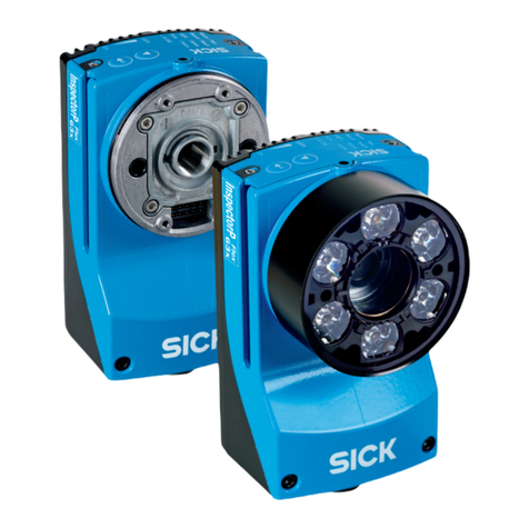
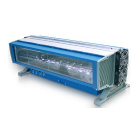
SICK Visionary-B Two User manual

OPERATING INSTRUCTIONS
Visionary-B Two
3D machine vision

Described product
Visionary-B Two
Manufacturer
SICK AG
Erwin-Sick-Str. 1
79183 Waldkirch
Germany
Legal information
This work is protected by copyright. Any rights derived from the copyright shall be
reserved for SICK AG. Reproduction of this document or parts of this document is
only permissible within the limits of the legal determination of Copyright Law. Any modi‐
fication, abridgment or translation of this document is prohibited without the express
written permission of SICK AG.
The trademarks stated in this document are the property of their respective owner.
© SICK AG. All rights reserved.
Original document
This document is an original document of SICK AG.
2O P E R A T I N G I N S T R U C T I O N S | Visionary-B Two 8028562/2023-12-07 | SICK
Subject to change without notice

Contents
1 About this document........................................................................ 5
1.1 Information on the operating instructions.............................................. 5
1.2 Symbols and document conventions...................................................... 5
1.3 Further information................................................................................... 5
2 Safety information............................................................................ 7
2.1 Basic safety notes..................................................................................... 7
2.2 Intended use............................................................................................. 7
2.3 Improper use............................................................................................. 8
2.4 Programmable device............................................................................... 8
2.5 Cybersecurity............................................................................................ 8
2.6 Qualification of personnel........................................................................ 9
3 Product description........................................................................... 10
3.1 Scope of delivery....................................................................................... 10
3.2 Type label.................................................................................................. 10
3.3 Product overview....................................................................................... 11
3.4 Display and control elements.................................................................. 11
3.5 SICK AppSpace......................................................................................... 12
3.6 Functionality.............................................................................................. 12
3.7 Interface standards.................................................................................. 15
3.7.1 GenICam™............................................................................... 15
3.7.2 GigE Vision®®......................................................................... 15
4 Mounting............................................................................................. 16
4.1 Planning for mounting.............................................................................. 16
4.2 Ventilation element................................................................................... 16
4.3 Mounting the product............................................................................... 17
5 Electrical installation........................................................................ 18
5.1 Prerequisites for safe operation of the device........................................ 18
5.2 Calculation rule......................................................................................... 21
5.3 Cable reserve on system plug.................................................................. 22
5.4 Pin assignment......................................................................................... 23
6 Configuration..................................................................................... 25
6.1 Software installation................................................................................. 25
6.1.1 Network settings...................................................................... 25
6.1.2 Installing SICK AppManager................................................... 25
6.1.3 Installing SICK AppStudio........................................................ 26
6.1.4 Installing SensorApp................................................................ 26
6.2 Programming the device.......................................................................... 27
6.3 Parameterizing GigE_Streamer_Basic..................................................... 27
6.4 Changing the IP address using GigE_Streamer_Basic .............................. 30
6.5 Changing the IP address using SICK AppManager................................. 30
CONTENTS
8028562/2023-12-07 | SICK O P E R A T I N G I N S T R U C T I O N S | Visionary-B Two 3
Subject to change without notice

7 Maintenance...................................................................................... 31
7.1 Maintenance............................................................................................. 31
7.2 Cleaning the product................................................................................ 31
8 Troubleshooting................................................................................. 32
8.1 Troubleshooting........................................................................................ 32
8.2 Repair........................................................................................................ 32
9 Decommissioning............................................................................. 33
9.1 Disposal of the product............................................................................ 33
10 Technical data.................................................................................... 34
10.1 Features.................................................................................................... 34
10.2 Mechanics and electronics...................................................................... 34
10.3 Dimensional drawing................................................................................ 35
10.4 Performance............................................................................................. 35
10.5 Interfaces.................................................................................................. 36
10.6 Ambient data............................................................................................. 37
11 Accessories........................................................................................ 38
12 Annex.................................................................................................. 39
12.1 Declarations of conformity and certificates............................................ 39
12.2 Licenses.................................................................................................... 39
CONTENTS
4O P E R A T I N G I N S T R U C T I O N S | Visionary-B Two 8028562/2023-12-07 | SICK
Subject to change without notice

1 About this document
1.1 Information on the operating instructions
Read these operating instructions carefully before starting any work in order to familiar‐
ize yourself with the product and its functions.
The operating instructions are an integral part of the product and should remain acces‐
sible to the personnel at all times. When handing this product over to a third party,
include these operating instructions.
These operating instructions do not provide information on the handling and safe
operation of the machine or system in which the product is integrated. Information on
this can be found in the operating instructions for the machine or system.
1.2 Symbols and document conventions
Warnings and other notes
DANGER
Indicates a situation presenting imminent danger, which will lead to death or serious
injuries if not prevented.
WARNING
Indicates a situation presenting possible danger, which may lead to death or serious
injuries if not prevented.
CAUTION
Indicates a situation presenting possible danger, which may lead to moderate or minor
injuries if not prevented.
NOTICE
Indicates a situation presenting possible danger, which may lead to property damage if
not prevented.
NOTE
Highlights useful tips and recommendations as well as information for efficient and
trouble-free operation.
Instructions to action
►The arrow denotes instructions to action.
1. The sequence of instructions is numbered.
2. Follow the order in which the numbered instructions are given.
✓The tick denotes the results of an action.
1.3 Further information
More information can be found on the product page.
The call is made via the SICK Product ID: pid.sick.com/{P/N}/{S/N}
{P/N} corresponds to the part number of the product, see type label.
{S/N} corresponds to the serial number of the product, see type label (if indicated).
ABOUT THIS DOCUMENT 1
8028562/2023-12-07 | SICK O P E R A T I N G I N S T R U C T I O N S | Visionary-B Two 5
Subject to change without notice

The following information is available depending on the product:
•Data sheets
•This document in all available language versions
•CAD files and dimensional drawings
•Certificates (e.g., declaration of conformity)
•Other publications
•Software
•Accessories
1 ABOUT THIS DOCUMENT
6O P E R A T I N G I N S T R U C T I O N S | Visionary-B Two 8028562/2023-12-07 | SICK
Subject to change without notice

2 Safety information
2.1 Basic safety notes
Please observe the safety notes and the warnings listed here and in other sections
of this product documentation to reduce the possibility of risks to health and avoid
dangerous situations.
CAUTION
Failure to observe the relevant work safety regulations may lead to physical injury or
cause damage to the system.
Danger due to optical radiation is product-specific. See the technical data for more
information.
Mounting and electrical installation
WARNING
Electrical voltage!
Electrical voltage can cause severe injury or death.
■Work on electrical systems must only be performed by qualified electricians.
■The power supply must be disconnected when attaching and detaching electrical
connections.
■The product must only be connected to a voltage supply as set out in the require‐
ments in the operating instructions.
■National and regional regulations must be complied with.
■Safety requirements relating to work on electrical systems must be complied with.
WARNING
Risk of injury and damage caused by potential equalization currents!
Improper grounding can lead to dangerous equipotential bonding currents, which may
in turn lead to dangerous voltages on metallic surfaces, such as the housing. Electrical
voltage can cause severe injury or death.
■Work on electrical systems must only be performed by qualified electricians.
■Follow the notes in the operating instructions.
■Install the grounding for the product and the system in accordance with national
and regional regulations.
2.2 Intended use
The Visionary-B Two 3D vision camera is suitable for 3D environment perception.
Applications
•Object detection and position determination
•Size and volume measurement
•Landmark detection
Possible uses
•Measurement data output (GigE_Streamer_Basic SensorApp pre-installed)
•Other SensorApp
•Programming a SensorApp for the product
The product is programmed within SICK AppSpace using the SICK AppStudio software
tool. SensorApps are installed using the SICK AppManager.
SAFETY INFORMATION 2
8028562/2023-12-07 | SICK O P E R A T I N G I N S T R U C T I O N S | Visionary-B Two 7
Subject to change without notice

Depending on the application, a browser-based graphical user interface (HMI) can be
created. The user interface offers options provided by the application developer for
controlling an application at the operator level.
The product offers various interfaces and operating elements for controlling, program‐
ming, and operating purposes, which can be activated as necessary via development
environments, control systems (programmable logic controllers), or applications. How‐
ever, configuration, programming, and control requires various technical skills, depend‐
ing on how the device is connected and used.
The product is intended for use in outdoor environments and mobile machines.
The product must only be used within the limits of the prescribed and specified techni‐
cal specifications and operating conditions at all times.
Incorrect use, improper modification, or tampering with the product will invalidate any
warranty offered by SICK AG. Furthermore, SICK AG shall not accept any responsibility
or liability for any resulting damage and consequential damage.
2.3 Improper use
Impermissible use
•As a safety component as defined in the relevant applicable safety standards for
machines, e.g. Machinery Directive
Impermissible ambient conditions
•Explosion-hazardous area
•Corrosive environment
2.4 Programmable device
The liability and warranty of SICK AG is limited to the device specification (hardware
functionality and any programming interfaces) according to the agreed conditions.
Therefore, SICK AG is not liable, among other things, for damages that are caused by
programming of the customer or third parties.
2.5 Cybersecurity
Overview
To protect against cybersecurity threats, it is necessary to continuously monitor and
maintain a comprehensive cybersecurity concept. A suitable concept consists of organi‐
zational, technical, procedural, electronic, and physical levels of defense and considers
suitable measures for different types of risks. The measures implemented in this
product can only support protection against cybersecurity threats if the product is used
as part of such a concept.
You will find further information at www.sick.com/psirt, e.g.:
•General information on cybersecurity
•Contact option for reporting vulnerabilities
•Information on known vulnerabilities (security advisories)
Cybersecurity of GigE Vision® and GenICam™ standard
•The product does not support operator authentication. Anyone connecting to the
product via Ethernet can carry out all processes (e.g., firmware update, restart,
configuration) without entering a password.
•All communication between the product and the computer (images, configuration,
protocols) is transmitted unencrypted via the UDP protocol.
•To receive security updates, update the product to the latest firmware.
2 SAFETY INFORMATION
8O P E R A T I N G I N S T R U C T I O N S | Visionary-B Two 8028562/2023-12-07 | SICK
Subject to change without notice

•Device detection according to GigE Vision® occurs via UDP port 3956. Other
communication occurs via dynamic UDP ports.
•When a product is connected, it must be located in a private network where the
access control is performed, for example, by separate firewalls.
2.6 Qualification of personnel
Any work on the product may only be carried out by personnel qualified and authorized
to do so.
Qualified personnel are able to perform tasks assigned to them and can independently
recognize and avoid any potential hazards. This requires, for example:
•technical training
•experience
•knowledge of the applicable regulations and standards
SAFETY INFORMATION 2
8028562/2023-12-07 | SICK O P E R A T I N G I N S T R U C T I O N S | Visionary-B Two 9
Subject to change without notice

3 Product description
3.1 Scope of delivery
No. of
units
Component Note
1 Product in the type ordered Depending on type
1 Printed safety notes, multilin‐
gual
Brief information and general safety notes
The actual scope of delivery may differ for special designs, additional orders or due to
the latest technical changes.
3.2 Type label
The type label contains information for identifying the product.
Visionary-B Two
V3S146-1AAAAAA
Product ID DC
Ptyp
Imax
IPcode
MAC 00:06:77:AC:2E:09
Manufactured: September 2023
≤ 13 W
1,6 A
IP67 / IP69 / IP6x9K
10 ... 57 V Class 2
pid.sick.com/
1234567/P/N
S/N 23020001
25 IND CONT. EQ.
4R97
SICK AG, 79183 Waldkirch, Germany Made in Germany XY
1
2
3
4
5
6
7
8
9
ß
Figure 1: Visionary-B Two type label (example)
1Product
2Supply voltage, typical power, maximum power consumption, IP enclosure rating
3MAC address
4Production date
5Conformity mark and certification mark
6Production site
7Data Matrix code
8QR code with a link to the product and more information
9Product ID
ßType designation
3 PRODUCT DESCRIPTION
10 O P E R A T I N G I N S T R U C T I O N S | Visionary-B Two 8028562/2023-12-07 | SICK
Subject to change without notice

3.3 Product overview
Product overview
1 2 3 4 5 6
8
7
9
Figure 2: Product overview for Visionary-B Two
1Power/IO connection
2Device status LED
3Application status LED
4Pressure compensation element
5Ethernet status LED
6Gigabit Ethernet connection
7Service interface
8Device coordinate origin
9Hole for mounting the mounting bracket (accessory)
Further topics
•Dimensional drawing
3.4 Display and control elements
Status LEDs
Device Application Description
O (all) O (Blue) Data transmission: API channel deactivated and diag‐
nostic channel active
O (all) Ö (Blue, flash‐
ing slowly)
Data transmission deactivated
O (all) O (Green) Data transmission: API channel active
PRODUCT DESCRIPTION 3
8028562/2023-12-07 | SICK O P E R A T I N G I N S T R U C T I O N S | Visionary-B Two 11
Subject to change without notice

Device Application Description
Ö (Blue, flash‐
ing slowly)
oSystem start
O (Green) Ö (Blue, flash‐
ing slowly)
Trigger mode active, waiting for trigger
Ö (Orange,
flashing slowly)
O (all) Device warning, e.g. temperature exceeds warning level
Ö (Red, flashing
slowly)
O (Red) Max. operating temperature exceeded
o = off; O = illuminated; Ö = flashing
3.5 SICK AppSpace
SICK AppSpace comprises software tools and programmable devices.
Support
Portal
PROGRAMMABLE DEVICES
TOOLS
APP DEVELOPERS
Sensor
AppPool
SensorApps
AM
AppManagerAppStudio
AS
Conference Sensor Integration
Machine
Figure 3: SICK AppSpace
Components and resources
•SICK AppManager: Software tool for installing and managing SensorApps and
firmware updates
•SICK AppPool: Cloud repository for storing and sharing SensorApps. SICKAppPool
can be accessed directly from SICKAppManager and SICKAppStudio as well as
via the web.
•SICK AppStudio: Software tool for developing SensorApps on programmable SICK
devices. The user interface for the machine operator can be created as a custom
web interface.
Complementary information
•Information about SICKAppSpace: www.sick.com/SICK_AppSpace
•SICK Support Portal with tutorials and instructions for programming the device in
SICK AppStudio: supportportal.sick.com
3.6 Functionality
The camera creates 3D images of the environment. Images are created using 3D
snapshot stereoscopy technology.
The camera captures two 2D images of the same scene from different angles and
superimposes the images. With the help of algorithms, a spatial representation of the
scene (3D point cloud) is created from the image overlay, comparable to human spatial
vision.
3 PRODUCT DESCRIPTION
12 O P E R A T I N G I N S T R U C T I O N S | Visionary-B Two 8028562/2023-12-07 | SICK
Subject to change without notice

Figure 4: Camera image left
Figure 5: Camera image right
PRODUCT DESCRIPTION 3
8028562/2023-12-07 | SICK O P E R A T I N G I N S T R U C T I O N S | Visionary-B Two 13
Subject to change without notice

Figure 6: 3D point cloud
The camera calculates the depth values. Depending on the product variant, the depth
map also contains color information for each measured value in the 3D point cloud.
Figure 7: Depth map
The working range can be flexibly extended thanks to the switchable field of view. The
working range and measurement accuracy can be adapted to the particular require‐
ments.
With the corresponding SensorApp for measurement data output, the camera within
a vision system can send the acquired measurement data to an external computing
unit for further processing. Alternatively, it is possible to process the acquired data
internally.
3 PRODUCT DESCRIPTION
14 O P E R A T I N G I N S T R U C T I O N S | Visionary-B Two 8028562/2023-12-07 | SICK
Subject to change without notice

3.7 Interface standards
3.7.1 GenICam™
GenICam™
GenICam™ is a standard that provides a generic application programming interface
for different kinds of cameras and devices. The standard is owned by EMVA (European
Machine Vision Association) and consists of multiple modules.
Compatible modules
Module Description
GenAPI Application Programming Interface (API) for parameterizing the
product
Standard Feature Naming
Convention (SFNC)
Standardized designations and typifications for common product
properties
GenTL General interface characteristics of the transport layer
GenTL SFNC Standardized names and types for features
Complementary information
Further information is available at www.emva.org/standards-technology/genicam/.
3.7.2 GigE Vision®®
GigE Vision®®
GigE Vision®® is an interface standard for cameras that is based on the Gigabit Ether‐
net communication protocol. The GigE Vision®® standard is owned by A3 (Association
for Advancing Automation). GigEVision®® cameras must support GenICam™.
Complementary information
Further information is available at https://www.automate.org/a3-content/vision-stand‐
ards.
PRODUCT DESCRIPTION 3
8028562/2023-12-07 | SICK O P E R A T I N G I N S T R U C T I O N S | Visionary-B Two 15
Subject to change without notice

4 Mounting
4.1 Planning for mounting
Installation site
•To prevent condensation, avoid exposing the device to rapid changes in tempera‐
ture.
•The mounting site is suitable for the weight of the device.
•Mount the device in a shock and vibration insulated manner.
•Protect the device from direct sunlight with a protection hood.
•Secure the fixing screws with threadlocker to prevent loosening. We recommend
using liquid threadlocker.
•Only mount the device using set screws in static applications or for short-term use.
For applications with permanent vibrations, secure the device using the threads on
the back of the housing.
•Do not seal off the ventilation element during installation.
Field of view
•Ensure a clear field of view for both cameras. Take the aperture angle into account
when doing so. Distance measurement is only possible if both cameras can see
the scene. An obstacle in one of the two fields of view can lead to gaps in the
depth map.
•Focus the field of view on the main area of the application. To reduce the amount
of sky in the picture, tilt the device forwards. Depth data can only be provided
for scenes with distinguishable contrast in the image and within the valid working
range.
4.2 Ventilation element
The ventilation element ensures an improved pressure equalization and allows the
exchange of air and heat between the housing and surroundings.
The breathable membrane allows ambient air to either penetrate into the device, or
escape again depending on the prevailing ambient conditions.
In particular for applications with frequently changing environmental influences (e.g.,
large temperature fluctuations or rapid temperature changes) or with standing water,
the ventilation element ensures a reliable pressure equalization and thereby relieves
the seals and adhesive joints of the housing. This can improve the expected service life
of the device in the application.
Note the following information:
•Do not affix any labels or stickers to the ventilation element.
•Do not paint over the ventilation element.
•Devices that have been subjected to a long period of moisture or very rapid
temperature changes need to first equilibrate after being switched on. In some
circumstances, therefore, a period of time should be allowed before measurement
readiness of the device because any moisture in the housing must first be taken
up by the air in the housing, which is heated up through the operation of the
device, so that it can then escape via the ventilation element. Depending on the
nature of the precipitated moisture, this time period might be several minutes or
even up to hours.
4 MOUNTING
16 O P E R A T I N G I N S T R U C T I O N S | Visionary-B Two 8028562/2023-12-07 | SICK
Subject to change without notice

4.3 Mounting the product
Approach
1. Mount the product in a suitably prepared bracket using the fixing holes provided.
Mounting brackets are available as accessories.
2. Make the electrical connection. Attach and tighten a voltage-free cable.
3. Align the vertical center line of the field of view of the product with the center of
the area to be monitored.
4. Switch on the supply voltage.
✓After successful initialization, the Device status LED lights up green. The product is
ready for operation.
5. Carry out a functional and vibration test. Realign the product if necessary. Protect
against excessive vibrations.
Further topics
•Pin assignment
•Dimensional drawing
MOUNTING 4
8028562/2023-12-07 | SICK O P E R A T I N G I N S T R U C T I O N S | Visionary-B Two 17
Subject to change without notice

5 Electrical installation
5.1 Prerequisites for safe operation of the device
Important information
WARNING
Risk of injury and damage caused by electrical current!
As a result of equipotential bonding currents between the device and other grounded
devices in the system, faulty grounding of the device can give rise to the following
dangers and faults:
•Dangerous voltages are applied to the metal housings.
•Devices will behave incorrectly or be destroyed.
•Cable shielding will be damaged by overheating and cause cable fires.
Remedial measures
•Only skilled electricians should be permitted to carry out work on the electrical
system.
•If the cable insulation is damaged, disconnect the voltage supply immediately and
have the damage repaired.
•Ensure that the ground potential is the same at all grounding points.
•Where local conditions do not meet the requirements for a safe earthing method,
take appropriate measures. For example, ensure low-impedance and current-carry‐
ing equipotential bonding.
Prerequisites for safe operation of the device
The device is connected to the peripheral devices (any local trigger sensor(s), system
controller) via shielded cables. The cable shield – for the data cable, for example –
rests against the metal housing of the device.
The device can be grounded through the cable shield or through a blind tapped hole in
the housing, for example.
If the peripheral devices have metal housings and the cable shields are also in contact
with their housings, it is assumed that all devices involved in the installation have the
same ground potential.
This is achieved by complying with the following conditions:
■Mounting the devices on conductive metal surfaces.
■Correctly grounding the devices and metal surfaces in the system.
■If necessary: low-impedance and current-carrying equipotential bonding between
areas with different ground potentials
5 ELECTRICAL INSTALLATION
18 O P E R A T I N G I N S T R U C T I O N S | Visionary-B Two 8028562/2023-12-07 | SICK
Subject to change without notice

SICK
Device
7 46
Power Supply
U
= 8
= 9
1 2 3
I
5
System
Controller
Figure 8: Example: Occurrence of equipotential bonding currents in the system configuration
1System controller
2Device
3Voltage supply
4Grounding point 2
5Closed current loop with equalizing currents via cable shield
6Ground potential difference
7Grounding point 1
8Metal housing
9Shielded electrical cable
If these conditions are not fulfilled, equipotential bonding currents can flow along the
cable shielding between the devices due to differing ground potentials and cause the
hazards specified. This is, for example, possible in cases where there are devices within
a widely distributed system covering several buildings.
Remedial measures
The most common solution to prevent equipotential bonding currents on cable shields
is to ensure low-impedance and current-carrying equipotential bonding. If this equipo‐
tential bonding is not possible, the following solution approaches serve as a suggestion.
NOTICE
We expressly advise against opening up the cable shields. This would mean that the
EMC limit values can no longer be complied with and that the safe operation of the
device data interfaces can no longer be guaranteed.
Measures for widely distributed system installations
On widely distributed system installations with correspondingly large potential differen‐
ces, the setting up of local islands and connecting them using commercially available
electro-optical signal isolators is recommended. This measure achieves a high degree
of resistance to electromagnetic interference.
ELECTRICAL INSTALLATION 5
8028562/2023-12-07 | SICK O P E R A T I N G I N S T R U C T I O N S | Visionary-B Two 19
Subject to change without notice

Electro-
optical
signal
isolator
Electro-
optical
signal
isolator
Power
Supply
SICK
Device
1 2 2 43
6 5
System
Controller
= 7= 8= 9
Figure 9: Example: Prevention of equipotential bonding currents in the system configuration by
the use of electro-optical signal isolators
1System controller
2Electro-optical signal isolator
3Device
4Voltage supply
5Grounding point 2
6Grounding point 1
7Metal housing
8Shielded electrical cable
9Optical fiber
The use of electro-optical signal isolators between the islands isolates the ground loop.
Within the islands, a stable equipotential bonding prevents equalizing currents on the
cable shields.
Measures for small system installations
For smaller installations with only slight potential differences, insulated mounting of the
device and peripheral devices may be an adequate solution.
5 ELECTRICAL INSTALLATION
20 O P E R A T I N G I N S T R U C T I O N S | Visionary-B Two 8028562/2023-12-07 | SICK
Subject to change without notice
Table of contents
Other SICK Machine Vision System manuals
