Ocular Robotics RobotEye REV25-ST User manual

ii
www.ocularrobotics.com Ocular Robotics Ltd
Revision Table
Copyright Notice and Disclaimer
Copyright 2013 Ocular Robotics Ltd (“Ocular Robotics”). All rights reserved.
No parts of this manual may be reproduced in any form without the express
written permission of Ocular Robotics.
Ocular Robotics makes no representations or warranties in relation to this User
Manual or the information and materials provided herein. Every precaution has
been taken in the preparation of this manual to include accurate and up to date
information. Ocular Robotics does not warrant that the information in this User
Manual is complete, true, accurate or non-misleading. Information contained
herein are subject to change without notice.
Ocular Robotics assumes no responsibility for errors or omissions or any
damages resulting from the use of the information contained in this handbook.
Date
Notes
27/05/2015
Initial Release

Table of Contents iii
www.ocularrobotics.com Ocular Robotics Ltd
Table of Contents
Revision Table...............................................................................................................................................................................ii
Table of Contents........................................................................................................................................................................iii
1 Introduction...............................................................................................................................................................................1
2 Basics ............................................................................................................................................................................................2
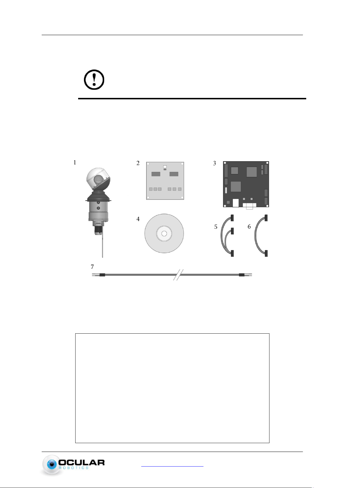
2.1 System Components ......................................................................................................................................................2
2.1.1 REV25-ST VISION - STABILIZED Unit ...........................................................................................................2
2.1.2 REV25-ST VISION - STABILIZED System .....................................................................................................3
2.2 What You Need.................................................................................................................................................................4
2.3 Handling and Transportation....................................................................................................................................4
2.4 Initial Setup .......................................................................................................................................................................5
2.4.1 REV25-ST VISION - STABILIZED Unit ...........................................................................................................5
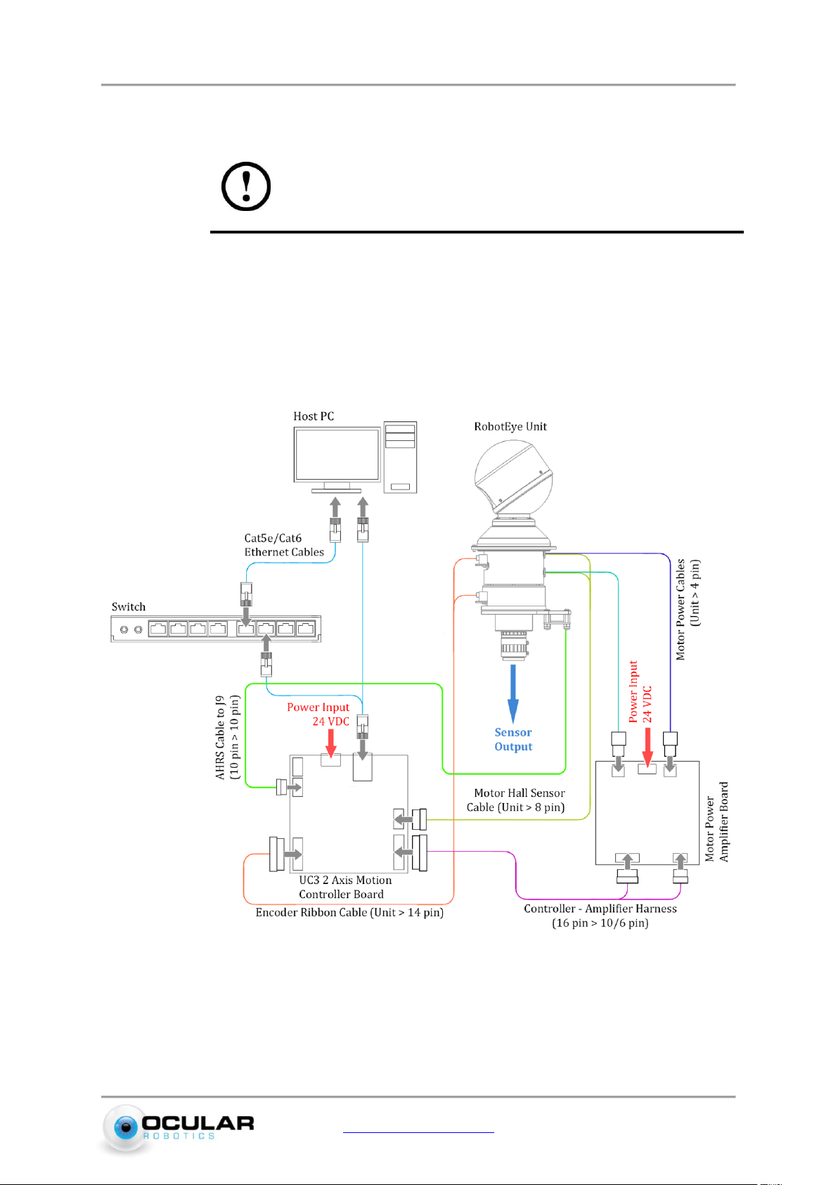
2.4.2 REV25-ST VISION - STABILIZED System .....................................................................................................7
2.5 Safety................................................................................................................................................................................. 10
2.6 Operation......................................................................................................................................................................... 11
2.7 Cleaning and Maintenance....................................................................................................................................... 12
2.7.1 Replacement Parts.............................................................................................................................................. 12
3 General Description............................................................................................................................................................. 13
3.1 Electrical.......................................................................................................................................................................... 13
3.2 Power................................................................................................................................................................................ 13
3.2.1 REV25-ST VISION - STABILIZED Unit ........................................................................................................ 13
3.2.2 REV25-ST VISION - STABILIZED System .................................................................................................. 13
3.3 Mechanical...................................................................................................................................................................... 15
3.3.1 REV25-ST VISION - STABILIZED Unit ........................................................................................................ 15
3.3.2 REV25-ST VISION - STABILIZED System .................................................................................................. 17
3.4 Ethernet ........................................................................................................................................................................... 19
3.4.1 REV25-ST VISION - STABILIZED Unit ........................................................................................................ 19
3.4.2 REV25-ST VISION - STABILIZED System .................................................................................................. 19
3.4.3 Network Topology.............................................................................................................................................. 20
3.5 Optical............................................................................................................................................................................... 21
3.5.1 Field of View.......................................................................................................................................................... 21
3.5.2 Camera Mounting................................................................................................................................................ 22
3.5.3 Camera Focus and Aperture........................................................................................................................... 23
3.5.4 Modulation Transfer Function ...................................................................................................................... 23
4 Specifications.......................................................................................................................................................................... 24

Introduction 1
www.ocularrobotics.com Ocular Robotics Ltd
1Introduction
IMPORTANT
READ CAREFULLY BEFORE USE
KEEP FOR FUTURE REFERENCE
The REV25-ST User Manual is provided as a guide to the connection, configuration and
safe use of the Ocular Robotics REV25-ST VISION - STABILIZED System. For
development of custom software applications for use with the REV25-ST system see the
RobotEye Network Interface Manual, RobotEye API Reference Manual, or contact Ocular
Robotics.
Chapter 2 Basics, describes the initial setup and basic use of the REV25-ST including
information on cleaning, maintenance and safety. Chapters 3 General Description
presents a system description in terms of the system’s Mechanical and Electrical
properties and its communication and power interfaces.
CAUTION - USE OF CONTROLS OR ADJUSTMENTS OR PERFORMANCE OF
PROCEDURES OTHER THAN THOSE SPECIFIED HEREIN MAY RESULT IN
SIGNIFICANT RISK OF INJURY. IT WILL ALSO VOID YOUR WARRANTY

Basics 2
www.ocularrobotics.com Ocular Robotics Ltd
2Basics
IMPORTANT –Before connecting the power to this system or
attempting to operate it in any way, read and follow all instructions
regarding safe operation of this system contained in section 2.5.
2.1 System Components
2.1.1 REV25-ST VISION - STABILIZED Unit
Figure 2.1 –REV25-ST Vision Unit Packing List
The Ocular Robotics RobotEye REV25-ST VISION - STABILIZED unit is supplied
standard with the following components, each of which can be seen in Figure 2.1:
1. The RobotEye REV25-ST VISION - STABILIZED unit.
2. Motor Power Amplifier Board.
3. 2-Axis Motion Controller Board.
4. Installation & documentation disk.
5. Cable Harness.
6. AHRS to Controller Board Cable Harness
7. REV25-ST VISION - STABILIZED unit power cable

Basics 3
www.ocularrobotics.com Ocular Robotics Ltd
2.1.2 REV25-ST VISION - STABILIZED System
Figure 2.2 –REV25-ST VISION - STABILIZED System Packing List
The Ocular Robotics RobotEye REV25-ST VISION - STABILIZED System is an REV25-ST
VISION - STABILIZED Unit mounted in an IP65* enclosure with power connector and
dual Ethernet connectors for RobotEye control and camera communication with the
following components, each of which can be seen in Figure 2.2:
1. The RobotEye REV25-ST VISION - STABILIZED System.
2. REV25-ST VISION - STABILIZED system power cable.
3. IP68 LAN cable (*optional).
4. Installation & documentation disk.
* To maintain the IP65 enclosure rating after installing or accessing the camera the base plate must be
replaced and base plate screws correctly tensioned

Basics 4
www.ocularrobotics.com Ocular Robotics Ltd
2.2 What You Need
In order to operate the REV25-ST VISION - STABILIZED unit and system, you will need:
1. Power supply –A 24 volt DC 10 Amp power supply with a continuous current
capacity of 10 Amps.
2. A suitable C-mount camera –Ocular Robotics can supply and mount a range of Allied
Vision Technologies GigE cameras.
3. Ethernet cable –A standard Ethernet cable (Cat5e or Cat6) is needed for control and
communication with the REV25-ST system.
4. Camera communications cable –All cameras supplied by Ocular Robotics have a
GigE communications interface.
5. A computer with a Windows or Linux operating system with one free 100 Megabit
Ethernet port.
2.3 Handling and Transportation
Avoid handling the RobotEye using the scanning head. This may result in mechanical
damage and misalignment of the sensor.
When transporting, make sure the RobotEye head will not be subject to large external
loads and stresses.
Figure 2.3 –REV25-ST Handling Zones

Basics 5
www.ocularrobotics.com Ocular Robotics Ltd
2.4 Initial Setup
NOTE –The robot eye head must be handled with extra care
during transport and installation. External loads exerted on the
head may result in damage.
2.4.1 REV25-ST VISION - STABILIZED Unit
Follow the steps below to set the REV25-ST unit up for use on a computer with a
Windows or Linux operating system. The library version number and system IP address
shipped with your system should be noted on the supplied Certificate.
Figure 2.4 Wiring and connections for the REV25-ST Unit
1. Connect Cable Harness (16 pin to 10/6 pin cable) between controller and amplifier
board.

Basics 6
www.ocularrobotics.com Ocular Robotics Ltd
2. Connect unit Encoder Sensor cable (14 pin connector) to black 2 Axis Motion
Controller board.
NOTE –Make sure the orientation of the connectors is correct.
Incorrect orientations may result in damage to the system.
3. Connect motor Hall Sensor cable (8 pin connector) from the unit to the black 2 Axis
Motion Controller board.
4. Connect Attitude and Heading Reference System (AHRS) cable (white 10 pin
connector) to the ARHS board. Connect the cable (black 10 pin connector) to J9
header on the 2 Axis Motion Controller board
WARNING - DO NOT CROSS CONNECT ARHS TO THE DIGITAL
I/O (J12) ON THE CONTROLLER BOARD. Doing so will cause
irreparable damage to circuits and/or equipment..
5. Connect motor power cables (4 pin white connectors) to the Motor Power Amplifier
board. Match the colour coding of the connectors to ensure correct operation,
incorrect connection of the motor power cables will result in uncontrolled motion of
the system on power up.
6. Connect both the 2 Axis Motion Controller board and Motor Power Amplifier board
to a 24 VDC power supply. Information on the polarity of the power connectors are
detailed in Section 3.2.
WARNING - Make sure the power supply is not powered before
connecting the cables.
7. Connect one end of the Ethernet cable to the network port on the PC or switch.
Connect the other end to the Ethernet port on the 2 Axis Motion Controller board.
8. Connect the chosen camera to the C-mount thread on the end of the REV25-ST unit.
A universal camera mount to suit all Allied Vision Technologies cameras
recommended for use with the REV25-ST VISION - STABILIZED product is supplied
with the REV25-ST VISION - STABILIZED Unit. If a different camera is chosen and it
can’t be used with the mount provided then alternative mounting arrangements
should be provided. DO NOT allow the camera to be unsupported on the camera
lens.

Basics 7
www.ocularrobotics.com Ocular Robotics Ltd
a) The camera lens should be rotated on the filter thread where it attaches to the
REV25-ST by the minimum amount required to align the body of the camera to
one of the two possible camera mount positions shown in Figure 3.11.
b) Remove two socket head screws in the base of the REV25-ST body in the chosen
position for the attachment of the camera mount (DO NOT have any more than
two screws removed from the base of the REV25-ST at any time). Place the
camera mount in position and replace the socket screws but do not tighten until
the mount is attached to the camera.
c) Use fasteners appropriate for your camera to fasten the camera to the mount and
then tighten the socket screws attaching the mount to the base of the REV25-ST
(Note –The screws used to attach the camera to the mount will need to be
loosened to focus the camera).
9. Attach power and communications cables as appropriate for your camera.
2.4.2 REV25-ST VISION - STABILIZED System
Follow the steps below to set the REV25-ST system up for use on a computer with a
Windows or Linux operating system. The library version number and system IP address
shipped with your system should be noted on the supplied Certificate.
1. Connect one end of the Ethernet cable to the network port on the PC or Switch.
Connect the other end to the REV25-ST Control Ethernet port (right-side Ethernet
connector). Refer to Figure 2.5.
2. Connect another Ethernet cable to the REV25-ST Camera Ethernet port (left-side
Ethernet connector) and a PC or Switch.

Basics 8
www.ocularrobotics.com Ocular Robotics Ltd
Figure 2.5 Wiring and connections for the REV25-ST System
3. Make sure the 24 volt power supply is switched OFF. Connect the supplied power
cable to the 24 volt power supply. On the unterminated end of the cable you will find
two wires one black and one with a red sheath on it. The black wire should be
connected to the negative terminal on the power supply. The cable with the red
sheath should be connected to the positive terminal on the power supply. The green
and yellow cable should be connected to a ground reference.
WARNING - Make sure the power supply is not powered before
connecting the cables.
4. Connect the power supply cable to the corresponding plug on the REV25-ST system.
Ensure the correct orientation by aligning the polarisation keys on the panel
connector and the plug. If forced in the incorrect orientation, damage to the system
is likely to result. Refer to Section 3.2.2 - Power for further details.
5. If your REV25-ST VISION - STABILIZED System was ordered complete with an Allied
Vision Technologies camera then your system should be ready to use. For adjusting
the Focus and Aperture of your camera see Section 3.5.3 - Camera Focus and
Aperture. Otherwise follow steps a) to i) to install your chosen camera.

Basics 9
www.ocularrobotics.com Ocular Robotics Ltd
a) Open the system enclosure by removing the eight countersunk socket screws
from the base.
b) Connect the chosen GigE camera to the C-mount thread on the end of the REV25-
ST unit. A universal camera mount to suit all Allied Vision Technologies cameras
recommended for use with the REV25-ST VISION - STABILIZED product is
supplied with the REV25-ST VISION - STABILIZED System. If a different camera
is chosen and it can’t be used with the mount provided then alternative
mounting arrangements should be provided. DO NOT allow the camera to be
unsupported on the camera lens.
c) The camera lens should be rotated on the filter thread where it attaches to the
REV25-ST by the minimum amount required to align the body of the camera to
one of the two possible camera mount positions shown in Figure 3.11.
d) Remove two socket head screws in the base of the REV25-ST body in the chosen
position for the attachment of the camera mount (DO NOT have any more than
two screws removed from the base of the REV25-ST at any time). Place the
camera mount in position and replace the socket screws but do not tighten until
the mount is attached to the camera.
e) Use fasteners appropriate for your camera to fasten the camera to the mount and
then tighten the socket screws attaching the mount to the base of the REV25-ST.
NOTE –The screws fastening the camera to the universal camera
mount must be loosened before adjusting the focus.
f) Attach the internal Ethernet cable from the enclosure camera Ethernet connector
to your GigE camera
g) The two pin connector shown in Figure 3.3 makes 24 VDC available for camera
power connection; a suitable converter from 24V to your camera’s required
voltage will need to be provided.
h) Follow the procedure in Section 3.5.3 to adjust the focus and aperture of the
camera.
i) Replace the base using the eight countersunk socket screws and tension
correctly to maintain the integrity of the seal.
6. Attach power and communications cables as appropriate for your camera.

Basics 10
www.ocularrobotics.com Ocular Robotics Ltd
2.5 Safety
The RobotEye REV25-ST VISION - STABILIZED System is a high speed device. All
instructions regarding safe operation of this system should be strictly followed.
Protection Class 3. The device operates with a separated extra low voltage
(SELV) of 24 Volts DC.
The device may only be operated as intended and in faultless condition. Safety
and warning signs must not be removed.
The REV25-ST VISION - STABILIZED System is in accordance with Ingress
Protection 65 (IP65). The device is protected against dust and jet water.
The REV25-ST VISION - STABILIZED Unit by itself is in accordance with
Ingress Protection 0 (IP00). The device is NOT protected against dust and jet
water.
All instructions regarding safe operation of this system should be strictly followed.
The user is responsible for the safe operation and maintenance of this system at all
times.
The REV25-ST is NOT intended for use by inexperienced personnel.
Installers of the sensor are responsible for ensuring their safe use in accordance
with all applicable regulations in the state, country or territory of use.
The device’s rotating head is not designed to accommodate for any alterations or
additions. High speed projectiles may result.
The device must be securely mounted during operation to prevent unstable motions.
Ensure that the Robot Eye head will not contact anything while operating in its full
range of movement.
Do not try to hold or touch the Robot Eye head while operating.
Do not attempt to disassemble the sensor. Improper disassembly will destroy the
optical alignment of the sensor and necessitate factory repairs. Tampering with any
enclosure will void warranty coverage.
The manufacturer will not accept liability for any resulting damages caused by the
non-observance of this manual or any unauthorised modification to the system.

11
www.ocularrobotics.com Ocular Robotics Ltd
2.6 Operation
Special precautions for when operating the device.
DO NOT attempt to touch or impede the Robot Eye head during operation.
Avoid strands of fabric or long exposed hair from being in the vicinity of the Robot
Eye head during operation. Significant injury and/or mechanical damage may result.
The REV25-ST's RobotEye head must be protected from direct impact.
Figure 2.6 Do not touch RE Head while in operation. Avoid impacts.
General considerations for when operating the device.
The REV25-ST should not be put into operation when the aperture is fogged or dirty.
The aperture should not be touched with bare hands. Refer to Section 2.7 for
cleaning the device.
The device must be protected against overheating. Persistent overheating of the
device will lead to reduced lifetime of the camera.
Additional protection is recommended when operating the device under extreme or
adverse environmental conditions. Rapid changes in temperature may lead to
humidity entering the device.

12
www.ocularrobotics.com Ocular Robotics Ltd
2.7 Cleaning and Maintenance
CAUTION –Power must be disconnected from the REV25-ST
system before any cleaning or maintenance is carried out.
User performable cleaning and maintenance of the RobotEye REV25-ST VISION -
STABILIZED System is limited to cleaning of the exterior housing and the aperture
window. For ANY other maintenance or repair the unit should be returned to the
factory. Unauthorised opening of the system enclosure will void warranty. Use the
following guidelines for cleaning of the system enclosure and aperture window.
It is VERY important not to abrade or scratch the system window during cleaning or
at any other time as it has the potential to significantly degrade system performance.
Use a soft non-abrasive cloth to clean the window, make sure there are no foreign
abrasive particles on the window before performing cleaning, as this may damage
the window.
DO NOT use solvents. If a cloth alone is not sufficient, water or Isopropyl Alcohol
may be used.
The rest of the REV25-ST VISION - STABILIZED System housing can be cleaned with
a soft damp cloth.
2.7.1 Replacement Parts
Replacement parts can be ordered directly through Ocular Robotics.
1) RobotEye REV25-ST System power cable.
2) IP68/IP69K Data cable (REV25-ST System).
a) An optional 5m or 10m IP68 Cable can be purchased from Ocular Robotics
3) 5mmx20mm 16A Slow Blow Fuse.
a) The fuse is located in the Fuseholder located above the left Ethernet connector.

General Description 13
www.ocularrobotics.com Ocular Robotics Ltd
3General Description
The RobotEye REV25-ST VISION - STABILIZED System is a three-axis high performance
VISION - STABILIZED system with unprecedented motion bandwidth. The REV25-ST
System is ideally suited for use on ground vehicles, surface craft, aircraft and other
dynamic platforms.
The REV25-ST’s embedded RobotEye technology allows applications such as inertial
stabilisation, object tracking, telepresence/teleoperation, environment mapping, rapid
disparate point data acquisition and persistent surveillance to be easily achieved.
3.1 Electrical
The REV25-ST VISION - STABILIZED System requires a 24 Volt DC power supply that
has a continuous current capacity of 10 amps. The output voltage of the 24 VDC power
supply used with the REV25-ST System should not vary by more than ±15% from the
nominal 24V under any circumstances otherwise damage to the REV25-ST System may
result.
3.2 Power
3.2.1 REV25-ST VISION - STABILIZED Unit
Power is supplied to the REV25-ST Unit via connectors as shown in Figure 3.1. Both the
2 Axis Motion Controller board and Power Amplifier board need to be directly powered
by the 24 VDC supply.
Figure 3.1 –Power connector on the controller and amplifier boards
3.2.2 REV25-ST VISION - STABILIZED System
Power is delivered to the REV25-ST System with the supplied 5 metre power cable. The
unterminated end of the power cable has two wires, one black and one with a red
sheath on it. The black wire should be connected to the negative terminal on the power

General Description 14
www.ocularrobotics.com Ocular Robotics Ltd
supply. The cable with the red sheath should be connected to the positive terminal on
the power supply.
During connection of the power supply cable to the corresponding plug on the REV25-
ST system, ensure the correct orientation by aligning the polarisation keys on the panel
connector and the plug. If forced in the incorrect orientation, damage to the system is
likely to result.
A 16A rated slow blow fuse is housed in the fuseholder to prevent potential damage to
internal electrical components from power surges.
Figure 3.2 –Fuseholder on the REV25-ST Enclosure
Power to the camera inside the enclosure is provided via a two-way connector. The red
wire provides 24 VDC with respect to the black wire at 0 V. A suitable voltage converter
is required if the camera operates at a different voltage.
Figure 3.3 –Power connector for the camera

General Description 15
www.ocularrobotics.com Ocular Robotics Ltd
3.3 Mechanical
3.3.1 REV25-ST VISION - STABILIZED Unit
The REV25-ST VISION - STABILIZED Unit has no environmental protection rating by
itself however as the RobotEye Head has a rating of IP65, it can adopt up to and
including this rating when housed in an appropriate enclosure. The REV25-ST can
operate in ambient temperatures of up to 70°C (The maximum operating temperature
of installed cameras may however be lower than this) making it suitable for use in a
wide range of industrial environments.
The bounding dimensions and positions of mounting holes for the REV25-ST Unit are
shown in Figure 3.4

General Description 16
www.ocularrobotics.com Ocular Robotics Ltd
Figure 3.4 –REV25-ST Unit Mechanical Dimensions

General Description 17
www.ocularrobotics.com Ocular Robotics Ltd
3.3.2 REV25-ST VISION - STABILIZED System
The REV25-ST VISION - STABILIZED System has an environmental protection rating of
IP65 and can operate in ambient temperatures of up to 70°C (The maximum operating
temperature of installed cameras may however be lower than this) making it suitable
for use in a wide range of industrial environments. The REV25-ST VISION - STABILIZED
enclosure has IP65 rating (when used with the cable socket and panel plug connectors
mated).
The bounding dimensions and positions of mounting holes for the REV25-ST System are
shown Figure 3.5.
Table of contents
Other Ocular Robotics Machine Vision System manuals
Popular Machine Vision System manuals by other brands

Safe Fleet
Safe Fleet 00-1109 R5 installation guide

Basler
Basler daA2500-60mc-SD820-DB8 Quick install guide

Panasonic
Panasonic A230 user manual

Sylvac
Sylvac VISIO 200 GL Instruction Manual Quick Start Version

Cognex
Cognex In-Sight 1700 Series user manual

Allied Vision
Allied Vision MAKO U-029B Technical manual