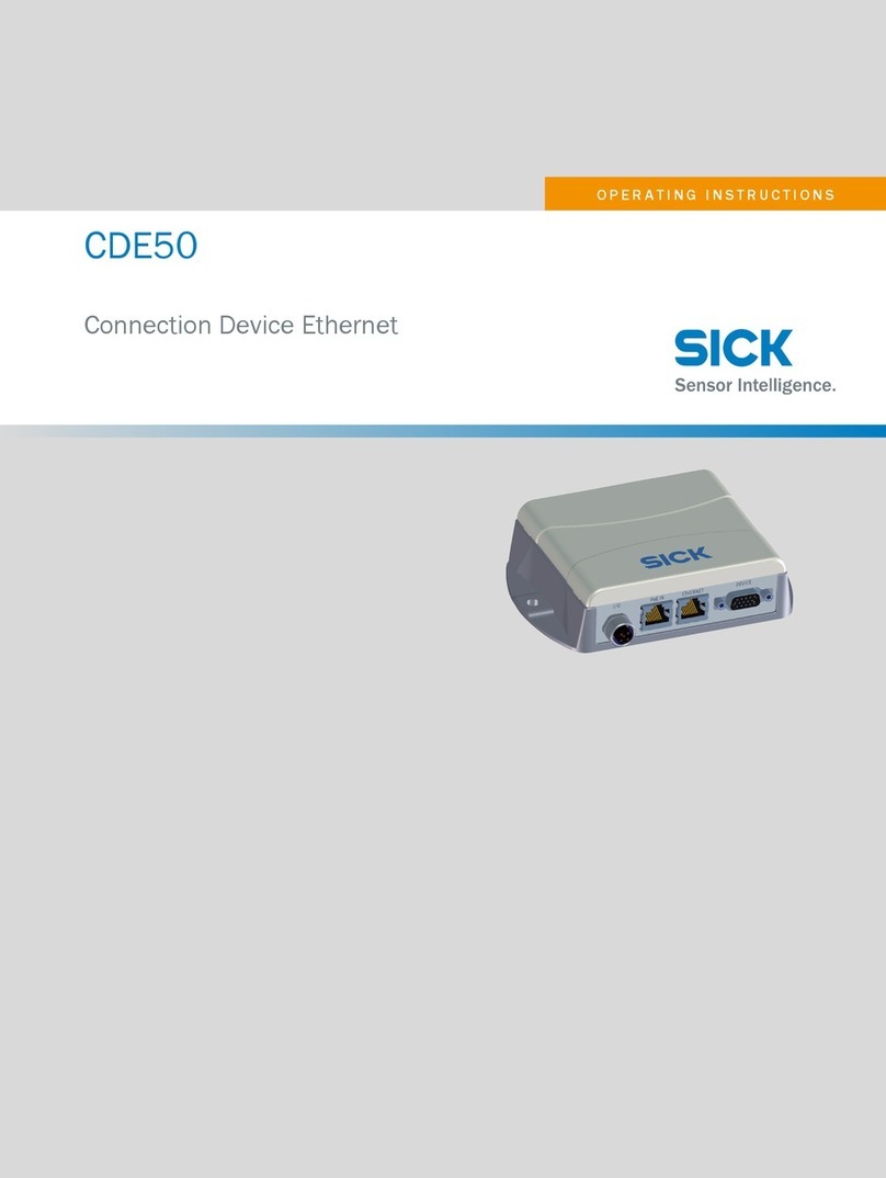
SICK IO-Link Master IOLG2EI-03208R01 EtherNet/IP User manual

EN
IOLG2EI-03208R01 – EtherNet/IP™
IO-Link Master
OPERATING INSTRUCTIONS

Operating instructions IO-Link Master IOLG2EI-03208R01 – EtherNet/IP™
2 ©SICKAG•PresenceDetection•Subjecttochangewithoutnotice•8018483
Copyright protection!
This work is protected by copyright. The associated rights
are reserved by
SICK AG. Reproduction of this document is only per-
missible within the limits of the legal determination of
copyright law. Alteration or abridgment of the document
is not permitted without the explicit written approval of
SICK AG.

©SICKAG•PresenceDetection•Subjecttochangewithoutnotice•8018483 3
Operating instructions IO-Link Master IOLG2EI-03208R01 – EtherNet/IP™
Contents
Contents
1 General information........................................................................... 5
1.1 Information on the operating instructions ...............................5
1.2 Explanationofsymbols .............................................................5
1.3 Abbreviations .............................................................................5
1.4 Limitationofliability ..................................................................6
1.5 Scopeofdelivery .......................................................................6
1.6 Customerservice.......................................................................6
1.7 EU declaration of conformity.....................................................7
2 Safety .................................................................................................. 8
2.1 Intended use .............................................................................8
2.2 Incorrect use ..............................................................................8
2.3 Requirementsforqualiedpersonnel......................................9
3 Setup and function .......................................................................... 10
3.1 Setup ....................................................................................... 10
3.2 Function................................................................................... 11
3.3 Status indicators and operating elements ........................... 11
4 Mounting .......................................................................................... 14
4.1 MountingtheIO-LinkMaster ................................................. 14
5 Electrical connection....................................................................... 14
5.1 Safety....................................................................................... 14
5.2 IO-Link Master electrical connection..................................... 15
5.3 Connection diagrams ............................................................. 16
5.3.1 Connection diagram for “POWER IN” and
“POWEROUT”supplyvoltage................................. 16
5.3.2 “EtherNet/IP™” connection diagram..................... 17
5.3.3 “IO-Link port” connection diagram ........................ 17
6 Systemintegrationandconguration............................................ 18
6.1 Integrating the IO-Link Master into the system..................... 18
6.2 ConguringtheIO-LinkMaster .............................................. 22
6.2.1 Dataconguration .................................................. 22
6.2.2 Congurationdata .................................................. 22
6.2.3 Moduleconguration.............................................. 23
6.2.4 IO-Linkportconguration....................................... 23

Operating instructions IO-Link Master IOLG2EI-03208R01 – EtherNet/IP™
Contents
4 ©SICKAG•PresenceDetection•Subjecttochangewithoutnotice•8018483
6.2.5 Input data................................................................ 24
6.2.6 Process data output ............................................... 26
6.3 IO-Linkobjectclasscode:0x96(CIPgeneric) ...................... 27
7 Operation on the IO-Link Master .................................................... 30
7.1 Statusindicatorsandoperatingbuttons .............................. 30
7.1.1 Operatingbuttons................................................... 30
7.1.2 ConguringdisplayLEDs ........................................ 31
7.2 Modes and displays................................................................ 31
7.2.1 Operating mode ...................................................... 31
7.2.2 Edit mode and fast-scroll mode............................. 31
7.2.3 Ping mode ............................................................... 31
7.3 Locking and unlocking edit mode for display ....................... 32
7.4 Commissioning ....................................................................... 32
7.5 Main menu .............................................................................. 33
7.6 “IP CONFIG” menu and changing address............................ 33
7.7 “IP SETUP” menu.................................................................... 35
7.8 “MODULEINFO”menu–
informationabouttheIO-LinkMaster ................................... 35
8 Operation via the web server .......................................................... 36
8.1 General information ............................................................... 36
8.2 Views........................................................................................ 36
9 Cleaning and maintenance ............................................................. 44
10 Disposal ............................................................................................ 44
11 Technical data.................................................................................. 45
11.1 Dimensions ............................................................................. 45
11.2 Supply...................................................................................... 46
11.3 EtherNet .................................................................................. 46
11.4 Operatingconditions .............................................................. 46
11.5 Constructional design............................................................. 46
Index .......................................................................................................... 47

©SICKAG•PresenceDetection•Subjecttochangewithoutnotice•8018483 5
Operating instructions IO-Link Master IOLG2EI-03208R01 – EtherNet/IP™
General information
1 General information
1.1 Information on the operating instructions
These operating instructions supplement the supplied QuickStart guide
andincludeadditionalinformationandmoredetaileddescriptionsofwork-
ingwiththeIOLG2EI-03208R01EtherNet/IP™IO-LinkMaster.
Theseoperatinginstructionsareintendedforqualiedpersonnelandelec-
tricalspecialistsandmustbereadbeforestartinganywork.
1.2 Explanation of symbols
Physical damage Warningsintheseoperatinginstructionsarelabeledwithsymbols.
Thesewarningsmustbeobservedatalltimesandcaremustbetakento
avoidphysicaldamage.
WARNING!
…indicatesapossiblehazardoussituationwhichmay
leadtophysicaldamageifitisnotavoided.
Tips and recommendations
NOTE!
… highlights useful tips and recommendations as well as
information for efcient and trouble-free operation.
1.3 Abbreviations
Abbreviation Description
DID DeviceID
EIP EtherNet/IP™
EMC Electromagneticcompatibility
FE Functional grounding
I Standard input port
ISDU IndexServiceDataUnit(IO-Linkservicedataparameters)
O Standard output port
VID VendorID
Table 1: Abbreviations

Operating instructions IO-Link Master IOLG2EI-03208R01 – EtherNet/IP™
General information
6 ©SICKAG•PresenceDetection•Subjecttochangewithoutnotice•8018483
1.4 Limitation of liability
Applicablestandardsandregulations,thelateststateoftechnological
development,andmanyyearsofknowledgeandexperiencehaveallbeen
takenintoaccountwhenassemblingthedataandinformationcontainedin
these operating instructions.
Themanufactureracceptsnoliabilityfordamagecausedby:
• Failingtoobservetheoperatinginstructions
• Incorrect use
• Usebyuntrainedpersonnel
• Opening the housing
• Unauthorizedconversions
• Technicalmodications
• Useofdefectivedevices
• Useofunauthorizedspareparts/consumableparts.
Withspecialvariants,whereoptionalextrashavebeenordered,orowingto
thelatesttechnicalchanges,theactualscopeofdeliverymayvaryfromthe
featuresandillustrationsshownhere.
1.5 Scope of delivery
Includedwithdelivery:
• IOLG2EI-03208R01 EtherNet/IP™ IO-Link Master
• 4M12blindplugsforsealingunusedIO-Linkports
• M4groundstrapwithM4x6screw
• 20labels
Supplieddocumentation:
• QuickStart
1.6 Customer service
Ifyourequireanytechnicalinformation,ourcustomerservicedepartment
willbehappytohelp.
Seethebackpageforyourrepresentativeofce.
NOTE!
In order to allow us to deal with the matter quickly, please
note down the type designation and order number before
calling. This information can be found on the side of the
IO-Link Master.

Operating instructions IO-Link Master IOLG2EI-03208R01 – EtherNet/IP™
Safety
8 ©SICKAG•PresenceDetection•Subjecttochangewithoutnotice•8018483
2 Safety
2.1 Intended use
The IOLG2EI-03208R01 IO-Link Master is a remote IO-Link
inputandoutputmoduleforintegrationintoanEtherNet/IP™network.
TheIOLG2EI-03208R01IO-LinkMastermayonlybeusedinapplicationsin
whichthesafetyofpersonneldoesnotdependonthedevicefunction.
SICKAGassumesnoliabilityforlossesordamagearisingfromtheuseof
theproduct,eitherdirectlyorindirectly.Thisappliesinparticulartouseof
the product that does not conform to its intended purpose and is neither
describednormentionedinthisdocumentation.
2.2 Incorrect use
TheIOLG2EI-03208R01IO-LinkMastermustnotbeusedinexplosive
environments.
Anyotherusethatisnotdescribedasacorrectuseisprohibited.
Noaccessoriesmaybeconnectedwhichhavenotbeenexplicitlystipulat-
ed,intermsofquantityandproperties,andapprovedbySICKAG.

©SICKAG•PresenceDetection•Subjecttochangewithoutnotice•8018483 9
Operating instructions IO-Link Master IOLG2EI-03208R01 – EtherNet/IP™
Safety
2.3 Requirements for qualiedpersonnel
WARNING!
Damage to the device in the event of improper han-
dling!
Improper handling may lead to physical damage.
Forthisreason:
• Allworkmustonlyeverbecarriedoutbythestipulated
persons.
Theoperatinginstructionsstatethefollowingqualicationrequirementsfor
thevariousareasofwork:
• Qualied personnel
areabletocarryouttheworkassignedtothemandindependently
recognizepotentialrisksduetotheirspecialisttraining,knowledge,and
experience,aswellasknowledgeoftherelevantregulations.
• Electrical specialists
areabletocarryoutworkonelectricalsystemsandindependently
recognizepotentialrisksduetotheirspecialisttraining,knowledge,and
experience,aswellasknowledgeoftherelevantstandardsandregula-
tions.
InGermany,electricalspecialistsmustmeetthespecicationsofthe
BGVA3WorkSafetyRegulations(e.g.,MasterElectrician).Otherrelevant
regulationsapplicableinothercountriesmustbeobserved.

Operating instructions IO-Link Master IOLG2EI-03208R01 – EtherNet/IP™
Setup and function
10 ©SICKAG•PresenceDetection•Subjecttochangewithoutnotice•8018483
3 Setup and function
3.1 Setup
US UA Mod Net100 LK1 100 LK2
EIP1 EIP2
POWER
IN
POWER
OUT
00 01 08 09
02 03 10 11
04 05 12 13
06 07 14 15
255
Fig. 1: IOLG2EI-03208R01 EtherNet/IP™ IO-Link Master setup
1 Functional grounding connection
2 EtherNet/IP port 1
3 Display with operating buttons and
two display LEDs
4 Output supply voltage
5 Status LED: IO-Link Master/
EtherNet communication
6 Port 00 / 01
7 Port 02 / 03
8 Port 04 / 05
9 Port 06 / 07
ß Mounting hole
à EtherNet/IP port 2
áLabel
â Input supply voltage
ã Port 08 / 09
ä Pin/port LEDs: Signal status
å Port 10 / 11
æ Port 12 / 13
ç Port 14 / 15

©SICKAG•PresenceDetection•Subjecttochangewithoutnotice•8018483 11
Operating instructions IO-Link Master IOLG2EI-03208R01 – EtherNet/IP™
Setup and function
Port mapping Port Labelling IO-Link Master
Port 0 Port 00 / 01
Port 1 Port 02 / 03
Port 2 Port04/05
Port 3 Port 06 / 07
Port4 Port 08 / 09
Port 5 Port 10 / 11
Port 6 Port 12 / 13
Port 7 Port14/15
Table 2: Port assignment
3.2 Function
The IOLG2EI-03208R01 IO-Link Master is a remote IO-Link
inputandoutputmoduleforintegrationintoanEtherNet/IP™network.
Theeightportscanbeconguredandusedindependentlyofoneanother.
TheycaneitherbeconguredasIO-LinkportsorstandardI/Oports.
TheIO-LinkMasterisintegratedandconguredusingprojectplanningsoft-
ware.Itcanalsobeoperatedviathedisplayorthewebserver.
3.3 Status indicators and operating elements
Overview
007
P
S↑
IP
SN
GW
0123
Fig. 2: Status indicators and operating buttons
1 Display LED (congurable)
2 Arrow pushbutton
3 Display
4 Set pushbutton
5 Display LED (congurable)
6 Cursor for selecting the
address type
7 Cursor for selecting the octet
IP IP address
SN Subnet address
GW Gateway address
0 Fourth octet
1 Third octet
2 Second octet
3 First octet

Operating instructions IO-Link Master IOLG2EI-03208R01 – EtherNet/IP™
Setup and function
12 ©SICKAG•PresenceDetection•Subjecttochangewithoutnotice•8018483
Operating buttons Pushbutton Description
↑•Select menu.
•Scroll through the menu.
•Ineditmode:Changevalue.
•Activatefast-scrollmode:Pressandholdpushbuttonin
edit mode.
S•Scrollthroughthemainmenu:Presspushbuttonbriey.
•Activateeditmode:Pressthepushbuttonforlongerthan
3 seconds.
•Ineditmode:Savevalueandscrolltothenextvalue.
•Inpingmode:Exitpingmode.
Table 3: Functions of the operating buttons
Function indicators (LEDs)
US UA Mod Net100 LK1 100 LK2
00 0901 08
1
2
Fig. 3: Function indicators (LEDs)
1 Status LEDs: IO-Link Master/EtherNet communication
2 Pin/port LEDs: Signal status
Pin/port LEDs: Pin 2 and pin 4 as-
signment Portconguredas Right LED Left LED
IO-Link port Pin4signalstatus Pin 2 signal status
Standard I/O port Pin 2 signal status Pin4signalstatus
Table 4: Pin/port LEDs: Assignment

©SICKAG•PresenceDetection•Subjecttochangewithoutnotice•8018483 13
Operating instructions IO-Link Master IOLG2EI-03208R01 – EtherNet/IP™
Setup and function
Status LEDs: IO-Link Master Function indicator Description
US •LEDlightsupgreen:SensorsupplyOK.
•LEDashesred:Sensorsupply<18V
UA •LEDlightsupgreen:ActuatorsupplyOK.
•LEDashesred:Actuatorsupply<18V
•LEDlightsupred:Noactuatorsupply
Mod •LEDashesgreen:IO-LinkMasterincorrectlycongured
ornotcongured
•LEDgreen:IO-LinkMasterisoperating
•LEDashesred:Fixedbusclockisnotpossible
•LEDashesred/green:Initialsequence
Net •LEDoff:
– IO-LinkMasterisoff/notsuppliedwithpoweror
– IO-LinkMasterisonbutnotconguredwithanIP
address
– TheIO-LinkMasterwasstartedbutthereisnoEIP
connection,e.g.,networkcableisnotpluggedin
•LEDashesgreen:IO-LinkMasterincorrectlycongured
ornotcongured
•LEDgreen:Connectionestablished
•LEDashesred:Connectiontimeout
•LEDashesred/green:Initialsequence
Table 5: Status LEDs: IO-Link Master
Status LEDs:
EtherNet communication Function indicator Description
100 •LEDoff:Busclock10Mbit/s
•LEDlightsupyellow:Busclock100Mbit/s
L/A1 and L/A2 •LEDgreen:Datatransfer
Table 6: Status LEDs: EtherNet communication
Pin/port LEDs: Standard I/O port LED display Description
Off TheI/Ostateoftherelevantinputoroutputpinis“0”
Yellow TheI/Ostateoftherelevantinputoroutputpinis“1”
Flashing red Short-circuitinsensorsupplybetweenpin1andpin3
Red Short-circuitonrelevantoutput,eitherbetweenpin2
andpin3and/orbetweenpin4andpin3
Table 7: Pin/port LEDs: Standard I/O port

Operating instructions IO-Link Master IOLG2EI-03208R01 – EtherNet/IP™
Setup and function
14 ©SICKAG•PresenceDetection•Subjecttochangewithoutnotice•8018483
Pin/port LEDs: IO-Link port LED display Description
Green IO-Link communication running
Flashing green No IO-Link communication
Green,fastashing IO-Link port in preoperate mode
Red,fastashing Datastorageorvalidationfailed.
Red IO-Linkshort-circuitbetweenpin3andpin4
Table 8: Pin/port LEDs: IO-Link port

©SICKAG•PresenceDetection•Subjecttochangewithoutnotice•8018483 15
Operating instructions IO-Link Master IOLG2EI-03208R01 – EtherNet/IP™
Mounting
4 Mounting
4.1 Mounting the IO-Link Master
>MounttheIO-LinkMasterusingthe2mountingholeswithM6screws
andwashers.
5 Electrical connection
5.1 Safety
Electromagnetic fault
WARNING!
Electromagnetic fault!
Electromagneticfaultcancausethedevice,system,or
nearbydevicestomalfunction!TheIO-LinkMastermeets
therequirementsofClassA(industrialapplications).Op-
erationinotherelectromagneticenvironmentsmaycause
faults or malfunctions.
• The operator must take appropriate precautions.
• OnlyconnecttheIO-LinkMastertoapprovedvoltage
supplies.
• Onlyuseapprovedcables.
Working with live parts
WARNING!
Equipment damage due to working with live parts!
Workingwithlivepartsmayresultindamagetothe
equipment.
• Onlyconnectanddisconnectcableconnectionswhen
thepowerisoff.
Incorrect supply voltage
WARNING!
Equipment damage due to incorrect supply voltage!
Anincorrectsupplyvoltagemayresultindamagetothe
equipment.
• Protectthesupplyvoltagewithmax.8Afuses.

Operating instructions IO-Link Master IOLG2EI-03208R01 – EtherNet/IP™
Electrical connection
16 ©SICKAG•PresenceDetection•Subjecttochangewithoutnotice•8018483
Excessive current load
WARNING!
Equipment damage due to excessive current load!
Anexcessivecurrentloadmayresultindamagetothe
equipment.
• Donotexceedthemaximumpermissibletotalcurrent
of 8 A for the IO-Link Master.
• Eachoutputprovidesamaximumcurrentof2A.
• Thesensors/busandactuatorsshouldbepoweredvia
separatecurrentsourcesifpossible.
Incorrect functional grounding
WARNING!
Incorrect functional grounding!
An incorrect functional grounding may result in equip-
ment damage or malfunction.
• ThegroundingbetweentheIO-LinkMasterandthe
machinemustbealow-impedancesystem.
• Thegroundconnectionmustbeasshortaspossible.
5.2 IO-Link Master electrical connection
1. Ensurepowersupplyisnotconnected.
2. Connect the IO-Link Master to the functional grounding of the system
using the supplied ground strap. See next page.
3. Connectsupplyvoltageto“POWERIN”usingasuitablecable.
4. ConnecteldbusconnectionviaEIP1/EIP2.
5. ConnectIO-LinkdevicesorstandarddevicestotheIO-Linkports.
6. Ifprovided,connectthenextgatewayto“POWEROUT”.
Functional grounding
Fig. 4: Ground connection

©SICKAG•PresenceDetection•Subjecttochangewithoutnotice•8018483 17
Operating instructions IO-Link Master IOLG2EI-03208R01 – EtherNet/IP™
Electrical connection
7. IO-LinkportsthatarenotinusemustbesealedwithM12blindplugs
to ensure the enclosure rating of IP 67.
NOTE!
Four M12 blind plugs are included in the scope of delivery.
5.3 Connection diagrams
5.3.1 Connection diagram for “POWER IN” and “POWER OUT” supply voltage
42
1 3
42
1 3
Supply voltage
Left: Input “POWER IN” 7/8” male connector, 4-pin
Right: Output “POWER OUT” 7/8” female connector, 4-pin
Contact Signal Description
124VDC Actuatorpowersupply
224VDC IO-LinkMasterand/orsensorpowersupply
3 0 V GNDIO-LinkMasterand/orsensorpower
supply
40 V GNDactuatorpowersupply
Table 9: Description of “POWER IN” and “POWER OUT” supply voltage

Operating instructions IO-Link Master IOLG2EI-03208R01 – EtherNet/IP™
Electrical connection
18 ©SICKAG•PresenceDetection•Subjecttochangewithoutnotice•8018483
5.3.2 “EtherNet/IP™” connection diagram
3
4
1
2
Fig. 5: EtherNet/IP™ connection diagram, M12 female connector, D-coded, 4-pin
Contact Signal Description
1 Tx+ Transmitter+
2 Rx+ Receiver+
3 Tx– Transmitter–
4Rx– Receiver
Table 10: EtherNet/IP™ description, M12 female connector, D-coded, 4-pin
5.3.3 “IO-Link port” connection diagram
3
5
4
1
2
Fig. 6: IO-Link port connection diagram, M12 female connector, A-coded, 5-pin
Port used as I/O port Contact Signal Description
1 L+ 24VDC,1.6A
2 I/O Inputandoutput(max.2A)
3 M GND
4I/O Inputandoutput(max.2A)
5 Not connected Not connected
Table 11: IO-Link port description, M12 female connector, A-coded, 5-pin
Port used as IO-Link port Contact Signal Description
1 L+ 24VDC,1.6A
2 I/O Inputandoutput(max.2A)
3 M GND
4IO-Link IO-Link,Inputoroutput(max.2A)
5 Not connected Not connected
Table 12: IO-Link port description, M12 female connector, A-coded, 5-pin
Forthedigitalsensorinputs,seeEN61131-2,type2.

©SICKAG•PresenceDetection•Subjecttochangewithoutnotice•8018483 19
Operating instructions IO-Link Master IOLG2EI-03208R01 – EtherNet/IP™
Systemintegrationandconguration
6 Systemintegrationandconguration
6.1 Integrating the IO-Link Master into the system
YoucandownloadthenecessaryEDSlesfrom“www.sick.com”.
TheintegrationoftheIO-LinkMasterisdescribedusingtheexampleofa
RockwellRSLogix5000.
Whenusingothercontrollersandsoftware,refertotherelevantdocumen-
tation.
1. Selectofinemode.
2. InstalltheEDSleviathe“Tools”menu,menuitem“EDSHardware
Installation Tool”.
3. Select“NewModule”viathecontextmenuinthe“EtherNet”directory.
4. SelecttheIO-LinkMasterinthe“Catalog”tab.
5. Clickthe“Create”button.

Operating instructions IO-Link Master IOLG2EI-03208R01 – EtherNet/IP™
Systemintegrationandconguration
20 ©SICKAG•PresenceDetection•Subjecttochangewithoutnotice•8018483
6. EntertheIPaddressinthe“General”tab.
7. Entertheconnectionparametersinthe“Connection”tab.
Table of contents
Other SICK Network Hardware manuals
Popular Network Hardware manuals by other brands

Amped Wireless
Amped Wireless AV3000 Setup guide

Carrier Access
Carrier Access 8015-24VDC quick start guide

D-Link
D-Link AirPlus DI-614+ Quick installation guide

SARAD
SARAD Net Monitors manual

Alvarion
Alvarion BreezeNET PRO.11 Series Specifications

S-Access
S-Access ETHERLINK IV Technical description and operations manual