SICK LGT 015 Parts list manual

TECHNICAL DESCRIPTION
LGT 015 – LGT 090
Safety Light Grids
‡HIGH AVAILABILITY †
‡MINIMUM DIMENSIONS †
‡UNIVERSAL APPLICATION †

2
8 007 487/10-10-99 Technical Description • LGT © SICK AG • Safety Systems • Germany • All rights reserved
Contents
The generally recognised rules
of engineering are carefully ap-
plied when developing and
manufacturing SICK equipment.
Naturally, all products comply
with the ISO 9000 quality
standard.
Approvals
EU Europe
TÜV Rheinland
Am Grauen Stein
51105 Köln
1 General 3
1.1 Features 3
2 Applications and
operating conditions 4
2.1 Applications 4
2.2 Operating conditions 5
2.3 General Notes on Safety
Protective Measures 5
3 System structure 6
4 Functions 6
5 Installation and
commissioning 7
5.1 General 7
5.1.1 Safety distance from
hazardous point 7
5.1.2 Distance from reflective
surfaces 8
5.1.3 Multiple safeguarding 8
5.2 Mechanical mounting 9
5.3 Electrical installation 9
5.3.1 Connection between
control unit and
customer interface 9
5.3.2 Switching outputs 10
5.3.3 Operating modes 11
5.3.4 Machine control 11
5.3.5 Test input 12
5.3.6 Contactor monitor 12
5.3.7 Sender power setting 13
5.3.8 Blanking 13
5.3.9 Behaviour of the
switching outputs in
various operating modes 14
6 Indicators and diagnostic
elements 15
6.1 Indicators on the sender
and receiver strips 15
6.2 Indicators in control unit 15
6.3 Seven-segment display
in control unit 16
7 Test instructions 17
7.1 Pre-commissioning tests 17
7.2 Regular checking of the
safety device by qualified
personnel 17
7.3 Daily checking of the
safety device by authorised
and instructed personnel 17
8 Technical data 18
9 Dimensions 19
10 Connection diagram 21
11 LGT Safety Light Grid
Selection 22
11.1 LGT selection table 22
11.2 Control unit and
Connection lead
Selection Table 23
11.3 Accessories
Selection Table 23
12 Check list 24
13 Conformity 25
Q
U
A
L
I
T
Y
S
Y
S
T
E
M
DIN EN ISO 9001
C
E
R
T
I
F
I
E
D
Reg.No. 19462-2

3
8 007 487/10-10-99 Technical Description • LGT © SICK AG • Safety Systems • Germany • All rights reserved
1 General
1 General
Fig. 1. Characteristic data of an LGT safety light grid
LGT Safety Light Screens are non
contact protective devices with a
resolution of 30 mm. They belong
to safety category 2 and as such are
testable protective devices. The
units are designed for operation in
industrial environments and are
characterised by the following fea-
tures:
‡High availability
‡Minimum dimensions
(10 x 30 mm2)
‡Stable construction
‡Universal application
‡Easy to install
The following characteristic data
are applicable in practice (Fig. 1).
Maximum width of protective field 6 m
Resolution (obstacle detection) 30 mm
Maximum height of protective field 905 mm
Minimum height of protective field 155 mm
1.1 Features
The main features of the LGT
safety light screen are:
‡Relay outputs
‡Up-to-date microprocessor
technology and specially de-
signed ICs (ASIC)
‡Easy to mount and adjust
‡Modular connection system
‡Only three components
(control unit, sender and
receiver strips)
‡Two sensor pairs can be con-
nected to one control unit
‡Double protective field height
by casading
‡Large signal reserve
‡EC approval
Height of protection field
Object
Resolution
Width of protection field

4
8 007 487/10-10-99 Technical Description • LGT © SICK AG • Safety Systems • Germany • All rights reserved
2 Applications and conditions of operation
Fig. 2. Point-of-operation guarding with an LGT Safety Light Grid
2.1 Applications
LGT Safety Light Grids are used for
point-of-point guarding (Fig. 2 and
3) and hazardous area guarding.
Typical applications include:
‡Form clamps as used in the
wood industry
‡Packaging machines
‡Processing centres
‡Production lines
‡Revolving transfer machines
‡Component insertion machines
‡Continuous lifts
‡Palletizers etc.
Fig. 3. Point-of-point guarding with an LGT Safety Light Grid Fig. 4. Point-of-point guarding with an LGT Safety Light Grid

5
8 007 487/10-10-99 Technical Description • LGT © SICK AG • Safety Systems • Germany • All rights reserved
2.2 Conditions of
Application
The machine or system must be
electrically controlled and it must
be possible to interrupt operation
at any time. When installing the
LGT, ensure that access above, be-
low or behind the protective zone
is not possible.
Operation and installation of pro-
tective devices are subject to the
relevant legal and official regula-
tions. These regulations vary ac-
cording to the application of the
light grid system.
2. Furthermore, our notes, in
particular the test regula-
tions (see chapter entitled Tests)
in this Technical Description or
these Operating Instructions
(such as use, assembly, installa-
tion or integration into the
machine control unit) must be
observed and followed.
3. The tests shall be carried out
by experts and/or persons
specifically authorized or
commissioned to perform
these tests. They shall be docu-
mented at all times in a clear and
concise comprehensible way.
4. Our Operating Instructions shall
be given to the employee
(operator) working at the
machine on which our protec-
tiveon equipment is used. The
employee shall be intro-
duced to his job and the
equipment by an expert.
5. This leaflet is enclosed as an
appendix and serves as a
checklist for checks carried out
by the manufacturer and fitter.
2.3 General Notes on
Safety Protective
Measures
1. The national/international
regulations apply for the use/
installation of non-contact
protectiveon equipment as well
as for commissioning and regular
recurring technical checks, in
particular
‡Machine directive 98/37 EC
‡Guidelines for working
substances 89/655 EEC
‡Machinery Safety regulations as
well as
‡Locally Enforced Regulations for
the prevention of accidents/rules
for safety.
It is the responsibility of the
manufacturers and users of the
machine on which our protec-
tiveon equipment is used, to
discuss all safety rules and
regulations which regulations,
which may apply with the
responsible authorities and to
observe these rules and
regulations.

6
8 007 487/10-10-99 Technical Description • LGT © SICK AG • Safety Systems • Germany • All rights reserved
3 System structure
The LGT Safety Light Grid com-
prises
‡Control unit LGTN
‡Sender LGTS and
‡Receiver LGTE
as well as the two connecting leads
to the control unit (
Fig. 5
).
4 Functions
3 System structure
Two sender and receiver units can
be connected to a LGTN control
unit.
If two sender units and two
receiver units are operated in paral-
lel the protective field height can be
doubled (
Fig. 6
).
Fig. 6. Two LGT safety light grid on a LGTN control unit: Double protective field height.
LGTN
2 x LGTS 2 x LGTE
max. 1800 mm
LGTN
LGTS LGTE
LGTN
Terminals for
sender and receiver
Fig. 5. LGT Safety Light Grid comprising a control unit LGTN, sender LGTS, receiver LGTE
and the two connecting leads to the control unit
The height of the protective field
depends on the size of the system
used.
The sender and receiver units of
the LGT contain a series of indi-
vidual elements which together
form a light grid of parallel beams.
If only one light beam is inter-
rupted, a switching command is
triggered which stops the machine.

7
8 007 487/10-10-99 Technical Description • LGT © SICK AG • Safety Systems • Germany • All rights reserved
5 Installation and Commissioning
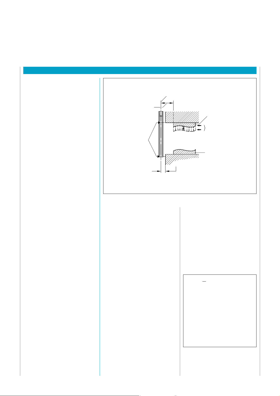
Fig. 7. Determining the coasting time and the safety clearance
For S < 500 mm
S = 2000 .....T + 8 (d - 14)
greater (S = > 500 mm)
S = 1600 .....T + 8 (d - 14)
S Safety distance
T Total response time in s
(stopping time of the machine
+ response time LGT)
d Resolution
The LGT must be commissioned in
accordance with the following steps
1 Clarify and carry out mechanical
mounting
2 Connect the sender and re-
ceiver strips to the control unit
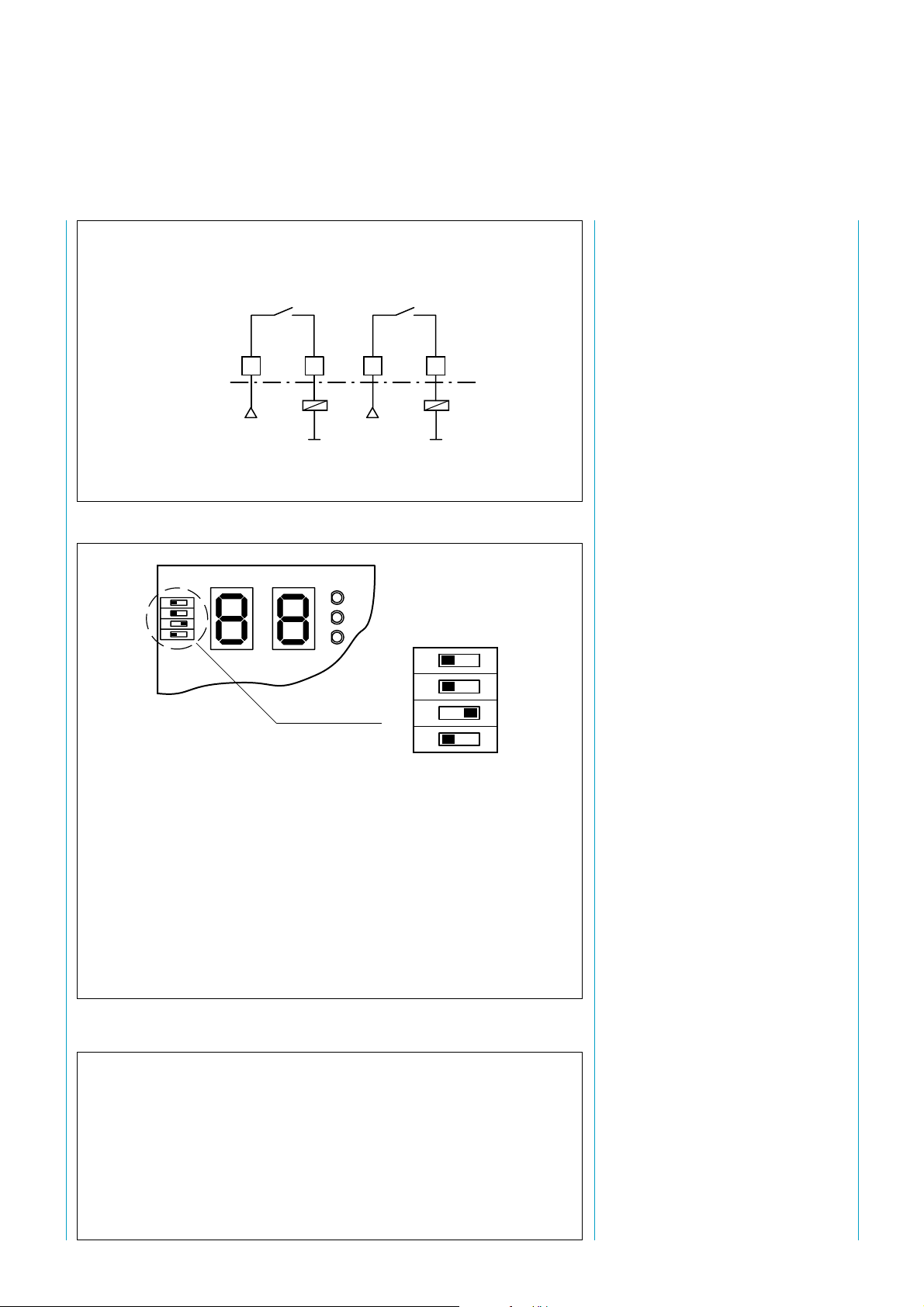
3 Set the DIP switches "With ...”
or "Without restart interlock"
(preset at factory), fig. 15
4 Connect the "machine control"
input (jumper or terminal)
5 Set the DIP switch: either 1 or
2 LGT connected to control
unit (fig. 15)
6 Connect or jumper the contac-
tor monitor
7 Perform blanking in accordance
with Section 5.3.8 if required
8 Set the sender power in ac-
cordance with 5.3.7
9 Insert the output elements in
the switch-off control line of the
machine
The individual measures for this
purpose are described in the fol-
lowing chapters.
5.1General
The LGT can be operated in any
position as long as the specified
safety distances and sufficient pro-
tective height are provided
(see 11 selection table).
Before the unit is installed, check
the components to ensure that
they are complete:
The LGT Light Grid comprises 5
individual parts. These must always
be available before starting the in-
stallation:
1 control unit LGTN
1 sender strip LGTS
1 receiver strip LGTE
2 connecting leads (preassembled)
Test rod (30 mm) as accessory
available.
Two sensor pairs (sender and re-
ceiver) can be connected to each
control unit.
5.1.1 Safety Distance from
Hazardous Point
The protective device requires a
certain minimum distance to the
hazardous point to ensure that the
point can only be reached once the
machine or system has come to a
standstill (Fig. 7). The safety dis-
tance (as per EN 775, 999 and
294) depends on the
‡stopping time of the machine,
‡response time of the protective
device,
‡resolution of the light grid
and the reach speed.
The stopping time is a measured
value of the machine. The reach
speed is equal to
at (short distances) up to 500 mm
safety distance 2 m/s
greater than this 1.6 m/s
The safety distance S is calculated
using the formula:
Mean protection field depth
S = Safety clearance Boundary of hazardous site
Protection field boundary
Upper edge of tool
Coasting time of machine
Lower edge of tool
This value must be strictly observed
in order to prevent access behind
the protection field.
≤ 75 mm

8
8 007 487/10-10-99 Technical Description • LGT © SICK AG • Safety Systems • Germany • All rights reserved
right
wrong
right
Light beam
interrupted
Central beam
R
R
RR
R
R
S
S
S
S
S
S
LGTS LGTE
4º
4º
a
Boundary of
hazardous site Reflective part
(e.g. container)
a (mm)
500
400
300
200
100
50
01 2 3 4 5 6
LGTS LGTE
8˚
a
a8˚
RW (m)
Fig. 8. Correct mounting and alignment. No reflection. The obstacle is clearly detected.
Fig. 9. Distance a as a function of the range RW
Fig. 10. Mounting two LGT systems in series
5.1.2 Distance to Reflective
Surfaces
Reflective surfaces located, placed
or mounted within the transmis-
sion and reception lobe can deflect
the light beams and may prevent an
object from being detected
(Fig. 8).
For this reason, a minimum dis-
tance abetween reflective objects
and the optical axis (straight-line
connection LGTS/E) must be ob-
served. The distance adepends on
the respective distance between
the sender and receiver and on the
alignment of the units (Fig. 9).
5.1.3 Multiple safeguarding
When using two LGT systems
(pairs), mutual interference must
be avoided between each safe-
guarded area. Since the light beams
diverge, the cross-section of the
beams increases proportionately to
the distance between the LGTS
and LGTE. The light beam must
only be received by the corre-
sponding LGTE. In order to pre-
vent mutual interference between
LGTs arranged in sequence, the
alignment must be taken into ac-
count when installing the units
(Fig. 10).
Direction of
approach

9
8 007 487/10-10-99 Technical Description • LGT © SICK AG • Safety Systems • Germany • All rights reserved
5.2 Mechanical mounting
The sender and receiver units must
not be installed rotated at 180°
angles to each other (Fig. 11).
The sender and receiver strips of
the light grid are secured in the light
screen by means of the threaded
M5 bolts or an M4 screw inserted
through the bolt hole or or the M5
bolt can be used directly (Fig. 12).
In order to ensure maximum flex-
ibility at the mounting location and
to enable light grids to be replaced
quickly, snap-on clips have been de-
veloped (Fig. 12). These can be di-
rectly screwed onto the mounting
surface. The light grids are then sim-
ply latched into place to prevent
the light grid from slipping as a re-
sult of vibration, the grid can
aditionally be secured to the clips
by means of a screw.
The control unit is screwed down
using the fixing holes provided in
the enclosure. When using the con-
trol unit without an enclosure, i.e.
mounting in a control cubicle, the
the control unit chassis is clipped di-
rectly onto a DIN rail.
To improve EMC, insulated moun-
ting on the power-driven machinery
is recommended. This can be provi-
ded by insulating (collared) washers,
for example.
Fig. 11. The sender and receiver units must
not be installed rotated at 180°angles to
each other.
5.3 Electrical installation
The preassembled connecting
leads must be used to connect
the control unit to the sender
and receiver strips. Insert the
connectors into the terminals
provided on the control unit.
(Fig. 13)
5.3.1 Connection between
the control unit and
customer interface
Depending on the type of control
unit, a supply voltage of 24 VDC
or 115/230 VAC must be pro-
vided and the unit connected in
accordance with the connection
diagram (Appendix 10).
Fig. 12. Fixing options for LGT
Fig. 13. Terminals for connecting sensor strips to the control unit
M4
M5
LGT
LGT
Clip
Clip
LGTN
R1 R2
S1 S2
S 1, R 1 Terminals for sender 1
and receiver 1
S 2, R 2 Terminals for sender 2
and receiver 2
S Sender
R Receiver
SE

10
8 007 487/10-10-99 Technical Description • LGT © SICK AG • Safety Systems • Germany • All rights reserved
5.3.2 Switching outputs
The control unit has four switching
outputs, each of which performs
different functions.
‡Main relay contact output
(
Fig. 14
),
‡Auxiliary relay contact output
(
Fig. 14
),
‡Protective Zone status
(PNP),
‡Contamination output
(PNP)
The main relay with positively actu-
ated contacts is the "safety" switch-
ing output of the LGT. The posi-
tively actuated contacts are moni-
tored by the control unit to ensure
that they are functioning correctly.
The auxiliary relay with its switching
output operates as a second, inde-
pendent switch-off path should the
main relay or controller fail.
We recommend fitting arc suppres-
sors to the contactors at the
outputs. This will extend the lives of
the relays in the LGTN and
suppress interference from external
sources.
The output circuits must be
provided with adequate protection
(e.g. with fuses) in accordance with
draft standard EN 50 100.
Fig. 15 shows the funktion of the
switches for setting the operating
mode of the LGTN
The status of the main and auxiliary
relays depends on the status of the
protective zone, the operating
mode "With restart interlock" or
"Without restart interlock" and the
command and test inputs.
LGTN
On variants with external mode switches:
Observe the seven-segment display during swizches.
Furthermore, floating blanking – although possible (at least in Germany) – is
not permitted. May be subject to national standards and/or risk assessment.
Before carrying out blanking again always check the functioning of all
beams (without blanking). After setting the blanking check that only the
desired beams are in fact blanked out.
Fig. 14. Output circuit elements
Fig. 15. Operating mode settings on the control unit
SwitchSwitch
SwitchSwitch
Switch PositionPosition
PositionPosition
Position FunctionFunction
FunctionFunction
Function
No.No.
No.No.
No.
4 ON "Calibration" mode active
OFF "Calibration" mode inactive (ready)
3 ON Number of connected sensor pairs: 1
OFF Number of connected sensor pairs: 2
2 ON "Mask" mode active
OFF "Mask" mode inactive (ready)
1 ON Operating mode without restart interlock
OFF Operating mode with restart interlock
4
3
2
1
Switch
No.
ON OFF
13
K1
Auxiliary relay contact
14 15
K2
Main relay contact
16

11
8 007 487/10-10-99 Technical Description • LGT © SICK AG • Safety Systems • Germany • All rights reserved
5.3.3 Operating modes
The LGT Light Grid can be oper-
ated "with..." or "without restart in-
terlock". This means:
In the operating mode "without re-
start interlock", the contact inputs
for the machine control must be
bridged.
5.3.4 Machine control
The control switch is used to close
the main relay and test relay con-
tact again in operating mode "with
restart interlock" when the protec-
tive zone is clear again after an in-
terruption or after a test has been
successfully performed (Fig. 18).
The machine can then resume op-
eration.
A make contact must be connected
to the input terminal strip.
A semiconductor output provides
the exact status of the protective
zone (Fig. 16). This output has no
safety relevance.
Prot. zone free: output live
Protective zone
interrupted: no output
The light grid is monitored con-
tinuously for contamination. The
status is signalled by means of the
contamination semiconductor out-
put (Fig. 17).
Light grid not
contaminated: no output
Light grid
contaminated: output live
78
RL
+24V
Fig. 16. The semiconductor output gives
the actual status of the protective zone
Fig. 17. Contamination semiconductor out-
put
910
RL
+24V
With restart interlock After the protective zone has been
interrupted or a test performed, the
contact of the main and auxiliary re-
lays do not close until the machine
control has been actuated. This
means that the machine cannot
resume operation until the protective
zone is clear again and the machine
control has been actuated.
If the duration of the test signal is less
than 100 ms, it is not necessary to
actuate the machine control.
The machine control must also be
actuated after the supply voltage has
been applied in this operating mode.
Without restart interlock After the protective zone has been
interrupted or a test performed, the
contact of the main and auxiliary re-
lays close immediately after the pro-
tective zone has been cleared. It is
not necessary to actuate the machine
control. Operating modes are set via
the DIP switches on the control unit
board.
Fig. 18. The machine control is implemented
as a make contact
12
+24V
+4V
–
1,2 kΩ
Control switch

12
8 007 487/10-10-99 Technical Description • LGT © SICK AG • Safety Systems • Germany • All rights reserved
Operating mode Action Indicators
„Without restart inhibit“ Break the protective field again LGTN lights up green
Switch the voltage on and off LGTN lights up green
„With restart inhibit“ Press the control switch LGTN lights up green
5.3.5 Test input
The test input is used to initiate a
test cycle (Fig. 19). In doing so, the
LGT including the main relay and
response time are monitored to
ensure that they are functioning
correctly. If a safety-relevant error is
detected during the test, the
switching ouputs remain open. The
machine, therefore, cannot resume
operation. A break contact must be
connected to the test input.
5.3.6 Contactor monitor
The external contactor monitor
monitors the contacts of connected
contactors to ensure that they are
do not stick (weld). These must be
connected to the LGT as shown in
the connection diagram (Fig. 20).
The contactor monitor monitors
the static rest position of the exter-
nal contactors. If a dynamic contac-
tor monitor is specified, the moni-
tor must be integrated into the
higher-order controller.
34
+24V
1.2 k
Test contact
U
high
> 15V
U
low
< 5V
Contact closed:
Contact open:
no test
test
56
+24V
U
high
> 15V
U
low
< 5V
1.2 k
K1 K2
Contactor
Fig. 19. Test input circuit Fig. 20. Contactor monitor circuit
Note
Safety can only be guaranteed if the
test input is used (installed in the
machine controller).
Note
If the protective field is broken very
briefly, a lockout together with the
error message 14 may occur in the
case of heavily rebounding contacts
(Table, below). The "Action" col-
umn gives the required measures.
If the contact monitoring is pro-
vided by externally connected de-
vices, terminals 5 and 6 must be
bridged.

13
8 007 487/10-10-99 Technical Description • LGT © SICK AG • Safety Systems • Germany • All rights reserved
5.3.7 Sender power
setting
The LGT has a sender power set-
ting option to enable the sender
power to be optimally matched to
the ambient conditions and to
match the control unit to the light
grid types (more than one pair in
use). This ensures that the aperture
angle always remains below the re-
quired value of ±4°thus preventing
unnecessary load on components.
The sender power is set as follows:
1 Mount the LGT in its final posi-
tion
2 Select "Calibration" mode: set
DIP switches (Fig. 15) set to
control unit print.
3 Switch on the power supply
A digit, which depends on whether
one or two light grids are con-
nected to the control unit, then
appears on the seven-segment dis-
plays:
Left-hand display for screen1
Right-hand display for screen 2
4 Adjusting the LGT strips for
maximum value on the seven-
segment display, e.g. "8"; range-
dependent (e.g. range 6 m –
display ≥2).
5 Deactivate "Calibration" mode:
DIP switches.
Caution:
There must be no intrusion into the
protective field during the
shutdown operation.
The sender power setting is thus
stored.
Once the sender power has been
set, the LGT is set for optimum
operation at the required installa-
tion position.
Important:
The sender power must always be
reset before the unit is commis-
sioned and each time the sender
and receiver strips are replaced.
5.3.8 Blanking
If mechanical brackets for guiding
material are located in the protec-
tive zone, this area must be
blanked out. For this purpose, up
to 4 beams on the LGT can be
blanked out, i.e. they no longer
have an effect.
Attention:
Since gaps in the protective field
are produced as a result of blanking,
these gaps must be guarded by
other (e.g. mechanical) safety
devices.
The blanking is set as follows:
1 Mount the LGT in its final position
2 Switch off the power supply
3 Select "blanking" mode: DIP
switches (Fig. 15)
4 Switch on the power supply
A digit then appears on the two
seven-segment displays, depending
on whether one or two light
screens are connected to the con-
trol unit. The digit indicates the
number of beams which are
blanked. After approx. 20 seconds
the seven-segment display switches
to a flash mode with "17", and the
yellow LED in the control unit lights
up. This means that the blanking
setting is stored. It is not possible to
blank out more than
4 beams.
5 Deactivate "blanking" mode: DIP
switches.
The blanking setting is thus stored.
6 Switch off the power supply and
switch it on again or upplug the
reset jumper and re-insert it.
7 Make sender powering as
described under 5.3.7.
After the blanking setting has been
completed, the protective zone
must be checked with a test rod
(30 mm Ø).
The blanking setting also remains
stored in the event of a power
failure.
An existing blanking setting is dis-
played continuously as per Fig. 21,
bottom.
Strip pair 1
blanked
Strip pair 2
blanked
Both strip pairs
blanked
Fig. 21. Blanking shown in display

14
8 007 487/10-10-99 Technical Description • LGT © SICK AG • Safety Systems • Germany • All rights reserved
5.3.9 Behaviour of the
switching outputs
in the various
operating modes
The switching outputs behave as
follows in the various operating
modes (Fig. 22 to 24).
ca. 1s 30 ms
90 ms
Supply on
voltage off
Main relay closed
(make contact) open
Auxiliary relay closed
(make contact) open
Standard switch-on period with start-up test
Fig. 22. Behaviour of the switching outputs after application of the supply voltage in operat-
ing mode "without restart interlock"
30 ms
20 ms
30 ms
< 50 ms
25...110 ms
approx.
100 ms
Control switch active
passive
Test input passive
active
Main relay closed
open
Auxiliary relay closed
open
Wait for control switch
Fig. 23. Behaviour of the switching outputs after machine initiation switch followed by a
short test request in the operating mode "with restart interlock".
Fig. 24. Behaviour of the switching outputs after machine control initiation followed by long
(≥150 ms) test request in the operating mode "with restart interlock"
30 ms
20 ms
30 ms
< 50 ms
> 150 ms
Control switch active
passive
Test input passive
active
Main relay closed
open
Auxiliary relay closed
open
Wait for control switch Wait for control switch

15
8 007 487/10-10-99 Technical Description • LGT © SICK AG • Safety Systems • Germany • All rights reserved
6 Indicators and diagnostic elements
6.1 Indicators in the sender and receiver strips
6 Indicators and diagnostic elements
yellow Operating indicator, lights up continuously when the supply
voltage is applied.
yellow Operating inidicator, lights up continuously when the
supply voltage is applied.
green Lights up continuously when the light path is not obstructed;
flashes if reception inadequate (due to contamination or
alignment error).
red Lights up when protective zone interrupted.
Sender
Receiver
In operating mode
"without restart interlock"
In operating mode
"with restart interlock"
green Lights up continuously when light path unobstructed and
after enable by machine control;
flashes if reception is inadequate (due to contamination or
alignment error.
red Lights up when protective zone interrupted.
yellow Lights up when the machine control must be operated.
green Lights up continuously when light path unobstructed;
flashes if reception is inadequate (due to contamination or
alignment error).
red Lights up when protective zone interrupted.
6.2 Indicators in the control unit

16
8 007 487/10-10-99 Technical Description • LGT © SICK AG • Safety Systems • Germany • All rights reserved
6.3 Seven-segment dis-
play in control unit
The two-digit seven-segment dis-
play (Fig. 25) provides information
on the status, faults, alignment,
number of blanked beams etc.
Error messages are displayed in
blinking mode.
The following information is im-
portant for fault diagnosis puposes:
After the fault has been rectified, the
control unit must be switched off and
on again. When the error has been
rectified, the control unit must be
switched off and then on again or the
reset jumper must be disconnected
and then reconnected. If contrary fault
messages are displayed on the seven-
segment display, check the connection
system. If the fault still cannot be recti-
fied, submit the unit for repair or con-
tact the SICK representative.
Fault Corrective measure
10
11
12
13
14
17
19
20
30
31
33
37
50
53
57
Check DIP switches and control unit connection
Check DIP switch setting
Check DIP switch setting, check plug-in connections
of the strips
Reset the sender power
Check contactor monitor (see 5.3.6 Contactor monitor)
Blanking procedure completed, reset DIP switches
Release "Test" button
Release "Machine Control" button
Check the sender and receiver type assignment.
Check connection system.
Check connections
Check plug-in connections and type assignment of
the strips
Re-calibrate sender power, check supply voltage
Check the sender and receiver type assignment
Check plug-in connections and type assignment of
the strips
Re-calibrate sender power, check supply voltage
Restart interlock configuration incorrect
(jumper or control unit input)
DIP switch setting "restart interlock" has
changed during operation
DIP switch setting "No. of LGT" does not
coincide wilth the actual number con-
nected
Incorrect sender and receiver configuration
Contactor monitor not working
Blanking successfully completed
Wait until "Test" button is again released
Wait until "Machine Control" button is re-
leased
No. of beams on sender and receiver not
identical
Sender and receiver reversed
Status signal error from strip 1
Excessively high received signal for given
range or supply voltage too low
No. of beams on sender and receiver not
identical
Status signal error from strip 2
Excessively high received signal for given
range or supply voltage too low
No.
Fig. 25. Seven-segment display

17
8 007 487/10-10-99 Technical Description • LGT © SICK AG • Safety Systems • Germany • All rights reserved
7 Test instructions
7 Test instructions
7.1 Pre-commissioning
tests
‡The pre-commissioning test
serves to confirm compliance
with safety requirements
specified in the national/interna-
tional regulations, in particular
the Directives governing
machinery or equipment use
(EC Declaration of Conformity).
‡Test of the efficacy of the safety
device on the machine in all
machine operating modes.
‡The personnel operating the
machine protected by the safety
device must be instructed as to
its use by qualified personnel of
the machine operating company
supplier before beginning work.
The said instruction is the
responsibility of the machine
operating company supplier.
7.2 Regular checking of the
safety device by qualified
personnel
‡Checks based on the applicable
national regulations at the
intervals specified therein. These
checks serve to reveal
modifications or manipulation of
the safety device since
commissioning.
‡The checks must be carried out
every time major changes are
made to the machine or the
safety device, as well as after
resetting or repair work in the
event of damage to the housing,
the front screen, the connecting
cables, etc.
7.3 Daily checking of the
safety device by
authorised and
instructed personnel
Run the 30 mm test rod slowly
through the protective field at three
points:
1. Protective field limits/markings
close to the sender (access
opening)
2. Protective field limits/markings
close to the receiver
3. Protective field limits in the
middle between sender and
receiver.
In the process only the red LED on
the LGTE may light up.

18
8 007 487/10-10-99 Technical Description • LGT © SICK AG • Safety Systems • Germany • All rights reserved
8 Technical Data of LGT Safety Light Grid
8Technical Data of LGT Safety Light Grid
1) A power supply unit with safeguarded isolation
(SEL V, PEL V circuit) must be used.
2) The voltage must not exceed or fall below the
limit values.
Caution: In the event of high-energy overvoltages
between DC supply and PE potential (≥ 0.5 kV)
a switch to AC supply and/or insulated mounting
of the sensor strips is recommended. In case of
interference also lay the sensor cables isolated
from the interfering cable duct.
3) Cannot be shortened.
Main relay
1
1
2
2
V DC
A
500 100 150 200 250
10
1,0
0,1
1
1
2
2
VDC
A
10 100 300200
10
1,0
0,1
Auxiliary relay
min. typ. max.
General system data
Protective field height 150 mm 900 mm
Protective field width 0.1 m 6 m
Resolution 30 mm
Wave length of the sender 880 nm
Protection class 1
Enclosure rating
Light grid IP 65
Control unit IP 54
or IP 20 (for cabinet installation)
Operating mode with or without restart inhibit
Supply voltage UV1)
DC 19.2 V 24 V 28.8 V
ripple 2) 5 Vss
or
AC 92 V 115 V 126.5 V
184 V 230 V 253 V
frequency 48 Hz 62 Hz
Power consumption 13 W
16 VA
Output
Main relay
resistive 4 A, 45 V DC
(see diagram)
inductive 4 A, 25 V DC
(see diagram)
Auxiliary relay
resistive 8 A, 55 V DC
(see diagram)
inductive 8 A, 15 V DC
(see diagram)
Protective zone status surge-proof
100 mA
UV– 2,5 V (HIGH) UV
600 µA (IQ)
Dirt indicator surge-proof
100 mA
UV– 2.5 V (HIGH) UV
600 µA(IQ)
Response time 50 ms
Length of connecting leads see 11.2 selection table 3)
Operating modes 0.1 mm21.5 mm2
Operating data
Safety category type 2
Requirements pr EN 50100
Operating temperature range – 10 °C + 55 °C
Humidity range 15 % 95 %
Storage temperature range – 25 °C + 70 °C
Dimensions See 9 Dimensions
Housing colour Cadmium yellow, RAL 10-21
Vibrostability 5 g, 10 ... 55 Hz to IEC 68-2-6
Shock resistance 10 g, 16 ms acc. IEC 68-2-29

19
8 007 487/10-10-99 Technical Description • LGT © SICK AG • Safety Systems • Germany • All rights reserved
9 Dimensions
9 Dimensions
LGT No. of Enclosure Prot. zone
type beams length height mm
a) b)
015 5 185 155
030 11 335 305
045 17 485 455
060 23 635 605
075 29 785 755
090 35 935 905
32,5
259,5
409,5
559,5
709,5
859,5
0
ø 7,5
M5
2,8
10
15
30
2,8
a)
x
72,5
25
12,5
(159,5)
15
b)
51,5
only LGT 015
1)
2)
x = mounting holes
1) Upper safety field limit is indicated by groove in housing
2) Lower safety field limit is 15 mm from end of housing
Fig. 26. Dimensions of sender LGTS, receiver LGTE

20
8 007 487/10-10-99 Technical Description • LGT © SICK AG • Safety Systems • Germany • All rights reserved
Fig. 27. Control unit dimensions LGTN
Fig. 28. Dimensional drawing of control unit for installation in a control cabinet
PG 11
Cable diameter 5 ... 12 mm
1 2 3 4 5 6 7 8 9 10 11 12 13 14 15 16 N L+
200
188
150
119
23
30 36 26,5
30
2324
75
SW 24
*)
*) To receive cables Remove sleeve and prise apart
1 2 3 4 5 6 7 8 910 11 12 13 14 15 16 N L+
70 170
126
57
Push the side panels
outwards to remove
the cover.
26
*)
**)
Suitable for installation in a control cabinet.
Suitable for mounting on a support rail to EN 50022 (high or low DIN rail) or EN 50035 (slide rail).
**) for mounting on low DIN rail (20 mm)
**) for mounting on high DIN rail (28 mm)
This manual suits for next models
5
Table of contents
Other SICK Relay manuals

SICK
SICK ReLy OSSD4 User manual

SICK
SICK LBV 330 User manual

SICK
SICK ReLy OSSD1 User manual

SICK
SICK ReLy HAND1 User manual

SICK
SICK ReLy EMSS3 User manual

SICK
SICK ReLy TIME1 User manual

SICK
SICK ReLy LOOP1 User manual

SICK
SICK ReLy OSSD4 User manual

SICK
SICK ReLy OSSD2 User manual

SICK
SICK ReLy OSSD3 User manual