Sicma MA Series Instructions for use

ORIGINAL INSTRUCTIONS
Shredder
MA - ML - MP
INSTRUCTION AND MAINTENANCE MANUAL


Shredder MA- ML-MP
- 3 -
SUMMARY
Par. Title P.
1. INTRODUCTION 5
2. GENERAL DESCRIPTION OF THE MACHINE 6
2.1 MILLING MACHINE COMPOSITION 7
3. GENERAL SAFETY INSTRUCTIONS 8
4. IDENTIFICATION OF THE MACHINE 9
4.1 IDENTIFICATION PLATE 9
4.2 IDENTIFICATION MARKINGS 10
4.3 INSPECTION OF MACHINE UPON DELIVERY 10
4.4 TECHNICAL DATA 11
5. SAFETY REGULATIONS: ADHESIVES AND WARNINGS 12
5.1 ADHESIVE LABELS DESCRIPTION 13
6. UNLOADING AND UNPACKING 14
7. INSTALLATION OF THE MACHINE 15
7.1 APPLICATION TO THE TRACTOR 15
7.2 TRANSPORTING THE SHREDDER 16
7.3 SPECIAL PROTECTIONS ON THE TRACTOR 17
7.4 ADAPTATION OF THE CARDAN SHAFT 18
8. RULES FOR USE OF THE SHREDDER 19
8.1 POSITION OF THE MACHINE IN RELATION TO THE GROUND 20
8.1.1 Adjustment of the levelling roller 20
8.1.2 Adjustment of slide rails 21
8.1.3 Adjustment third arm 21
8.1.4 Work positions of the machine 22
8.1.5 Start of work 22
9. ORDINARY MAINTENANCE 23
9.1 ADJUSTMENT OF THE BELTS AND REPLACEMENT 24
9.2 REPLACEMENT OF KNIVES OR HAMMERS 25
9.3 TABLE OF TIGHTENING TORQUES 26
9.4 SPECIAL ACCESSORIES: - OPENING HOOD 26
9.5 TABLE OF LUBRICANTS 27
10. PROBLEMS AND SOLUTIONS 27
11. TEMPORARY SHUTDOWN OF THE SHREDDER 28
12. DISMANTLING 28
13. TECHNICAL ASSISTANCE 28
14. WARRANTY 28
14.1 EXPIRY OF THE WARRANTY 29
11. TEMPORARY SHUTDOWN OF THE SHREDDER 29
12. DISMANTLING 29
13. TECHNICAL ASSISTANCE 30
14. WARRANTY 30
14.1 Expiry of the warranty 30

- 4 -
Shredder MA-ML-MP
ATTENTION !
IT IS PROHIBITED TO USE THE SHREDDER WITH-
OUT CONSULTING THE INSTRUCTION AND MAIN-
TENANCE MANUAL
Read this manual carefully; in case of dif!culty in understanding do not use
the machine and if clari!cation is required request information from your au-
thorised retailer or from the manufacturer.

Shredder MA- ML-MP
- 5 -
1. INTRODUCTION
This manual is an integral part of the product and must be kept in an ap-
propriate manner, allowing easy consultation by the operator at any time. It
is advisable to make a copy of this manual.
This manual is accompanied by the "DECLARATION OF CONFORMITY"
that certi!es compliance with the regulations in force and that must be pre-
sented to parties that expressly request it.
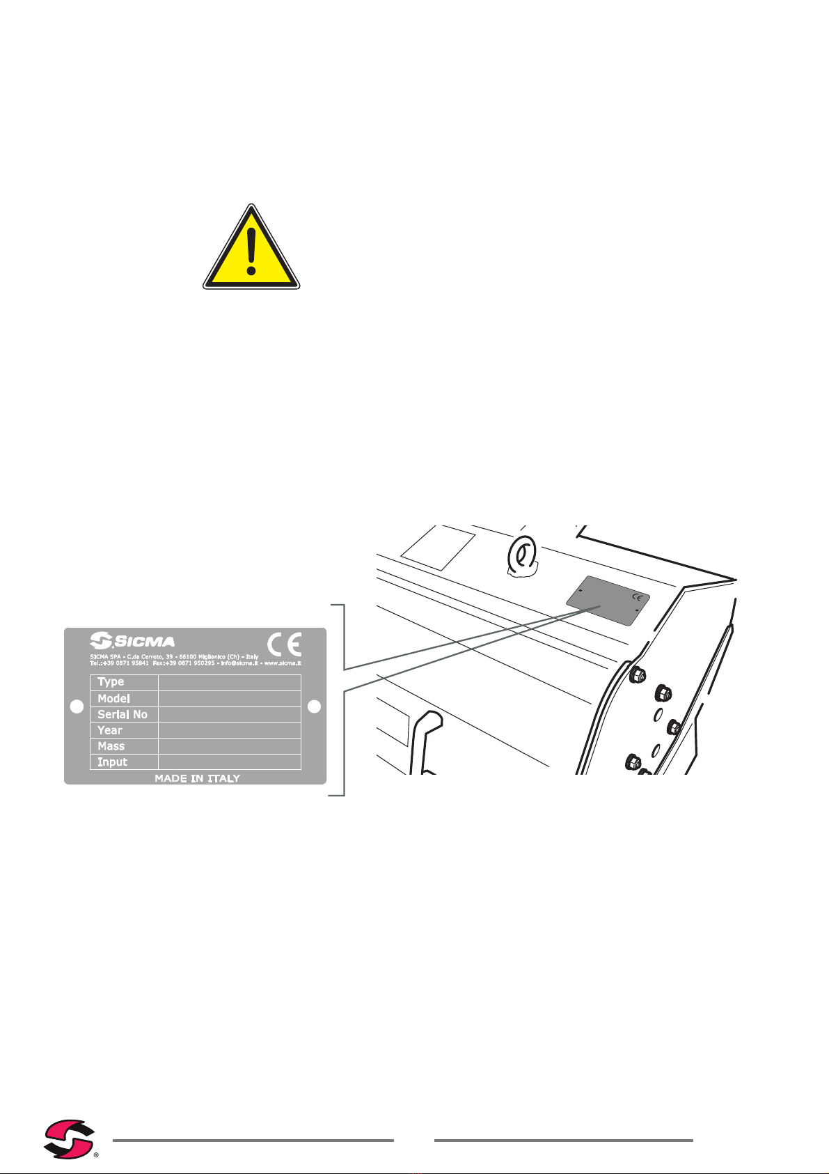
In addition, this declaration shows the "SERIAL NUMBER" of the machine.
Upon delivery check correspondence of the serial number of the machine.
Where there correspondence of the numbers is incorrect, immediately con-
tact the retailer to check the details.
"Sicma" thanks you for having chosen this excellent product.
During operation you will have the opportunity to appreciate the quality of
use and durability of your machine.
In order to maximise the qualities of this machine, it is advisable to spend a
little of your valuable time reading this manual. Superior knowledge of the
machine will pay dividends in terms of duration, safety and quality in the
productive use.
In case of uncertainty, please contact the authorised retailer that will advise
you, offering the appropriate support in the shortest time possible.
Your "SHREDDER" was designed exclusively
for agriculture use. Any other use of the ma-
chine is to be considered abusive and is whol-
ly at the risk of the user. In such case the legal
warranty ceases.
Appropriate use also involves compliance with
the instructions of service and maintenance
prescribed by the manufacturer.
Only authorised persons that are informed
about the possible risks must use, repair and
maintain the machine.
The relevant instructions for the prevention of
accidents must be observed as well as all the
other general technical provisions, the High-
way Code and regulations relating to health
and safety.
Never make any changes to the machine un-
der your own initiative. Where this is the case,
no liability can be held for any damage caused
to persons or property. In this case the legal
warranty also ceases with immediate effect .
"Sicma" reserves the right to suspend at any time the production of certain
models, to vary the characteristics and the design without being committed
in any shape or form to provide notice thereof and is not obliged to apply
these changes to models that have already been produced.
Ap

- 6 -
Shredder MA-ML-MP
2. GENERAL DESCRIPTION OF THE MACHINE
ATTENTION!
Where the shredder is delivered packaged, the elements of the packaging
must not be left discarded as potential sources of risk. Remove the above
to the appropriate collection places if they are contaminants and/or biode-
gradable.
Fig. 1
Shredder MA
Fig. 2
Lifting unit
- 3 arms
The shredder series MA, ML, MP consist of a body of steel that supports all
the parts of the machine; it is designed in such a way as to ensure perfect
working of the product without the need for high powers, in compliance with
the applicable safety standards.
The articulation is secured to the main frame that allows the machine to
be tilted; two arms are connected to the joint for lateral movement, and the
three-point connection is attached to the arms.
The machine is able to perform rotations with respect to the ground of 65°
and 90° by means of a hydraulic control, operated exclusively on board the
tractor; in addition the shredder, via the hydraulic control arms can perform
lateral movements.
Within the body is housed the rotor supported by high strength bearings and
driven by transmission belts that take motion from the side transfer of the
box to the gears or revolution multiplier. The rotor is dynamically balanced
for homogeneous rotation without vibration.
The number of knives or hammers with which the rotor is equipped guaran-
tee perfect shredding of the material and adequate ventilation.

Shredder MA- ML-MP
- 7 -
At the time of purchase the shredder is as shown in Fig. 1, and is designed
to be installed on the rear of the tractor that will need to be !tted with a "uni-
versal" rear hydraulic 3-point lift unit, second category, for the models MA,
ML and third category for the mod. MP suitable to withstand the weight and
absorption characteristics of the shredder.
The hitch is shown in Fig. 2
ATTENTION!
Before performing any operation carefully read the safety requirements
shown here.
2.1 Shredder composition
Fig. 3
Main
elements
No. Description
1 Three-point connection
2 Quick coupling hydraulic connec-
tions
3 Support arm and movement
4 Foot support
5 3° point plug
6 Main frame
7 "EC" rubber protection
8 Protection cardan joint
9 Slide rail
10 Power take-off (PTO 540 RPM)
11 Transmission belt housing
12 Gear box
13 Openable hatch for maintenance
14 Machine tilt articulation
4
3
2
114 12 11
5 6 7 8 9
10
13

- 8 -
Shredder MA-ML-MP
3. GENERAL SAFETY INSTRUCTIONS
It is recommended to carefully read these annotations in order to avoid situ-
ations of danger.
1) In addition to the information in this manual it is also similarly important
to respect the general provisions relating to safety, provided for the users of
agricultural machines by current legislation of each country.
2) Observe the decals on the machine, especially those that relate to safety.
3) Only start the shredder in the resting position on the ground and horizon-
tal to the ground.
4) Never exceed the speed of the prescribed PTO (540 rpm).
5) Secure the protector tube of the cardan shaft against the rotation by con-
necting the chains in order to prevent rotation of the protective elements of
the cardan shaft.
6) Lower the machine to the level of the ground before putting it in the work
position. Ensure there are no persons in the range of action of the machine.
7) Ensure that the security devices are perfectly !tted and ef!cient before
starting work.
8) Pay special attention on stony ground, ensuring that there are no persons
in the immediate vicinity.
9) Before any interventions on the shredder, ensure that all the rotary mem-
bers are stationary and switch off the tractor by removing the start key.
10) During transfer onto public roads, observe the Highway Code.
11) Use particular caution during the operations of coupling and uncoupling
of the tool from the tractor.
12) Before leaving the tractor, secure the tool and lower it until resting on the
ground. Switch off the tractor and remove the start key.
13) Before engagement and release of the machine at the three-point hitch,
lock the hydraulic lifting controls of the tractor in order to avoid, even in-
advertently, the hydraulic lift being activated resulting in movement of the
shredder.
14) Ensure that the maximum loads permitted for the three-point hitch are
respected.
15) Perform assembly and disassembly of the cardan shaft only with the
PTO disabled and the engine of the tractor off with the ignition key removed.
16) Before engaging the PTO, ensure that the speed and direction of rota-
tion of the power take-off of the tractor are compatible with the shredder.
17) Never engage the PTO with the engine running.
18) Before engaging the PTO, ensure there are no persons in the work
area.
19) Do not allow anyone to stand near the PTO when this is engaged.
20) Before accessing the tool ensure that this is completely stopped and
that the engine of the tractor is stopped and the PTO is off.

Shredder MA- ML-MP
- 9 -
21) Periodically check the tightness of screws and nuts. Where necessary
tighten with reference to the tightening table in paragraph 9.3.
22) During maintenance work performed with the tool raised, ensure that
it is securely in the elevated position safely through the use of appropriate
supports.
In the case of repairs please contact specialist workshops.
23) Dispose of oil and grease by observing the relevant rules in force.
IMPORTANT !
The shredder models MA, ML, MP were designed and manufactured for
agricultural use and designed to operate, in accordance with the manu-
facturer's instructions, within the limits shown in this manual. No liability is
assumed for any damage to property or persons caused by improper use
of the machine.
4. IDENTIFICATION OF THE MACHINE
4.1 Identi"cation plate
Shredder
MA140
00218
2014
147 Kg
540 rpm
Fig. 4
Identi!cation plate
Fig. 5
Plate position

- 10 -
Shredder MA-ML-MP
4.2 Identi•cation markings
The shredders of the company Sicma models "MA, MLI, MLE, MPI, MPE"
are available in the following work widths and models :
Internal transmission unit External transmission unit
Model Work width mm Model Work width mm
MA 120 1150
MA 140 1350
MLI 140 1330 MLE 140 1330
MLI 160 1530 MLE 160 1530
MPI 180 1800 MPE 180 1800
MPI 200 1960 MPE 200 1960
4.3 Inspection of machine upon delivery
At the time of delivery of the shredder check the entire supply, ensuring in
particular the presence of the instruction and maintenance manual that is an
integral part of the machine.
The following items must be delivered together with the shredder:
- no. 1 shredder operation and maintenance manual Fig.6
- no. 1 operation and maintenance manual for cardan shaft Fig.7
- no. 1 declaration of conformity Fig.8
Lorenzo Aurora
AMMINISTRATORE UNICO
EC DECLARATION OF CONFORMITY
The company
Sicma s.p.a.- C.da Cerreto,39 - 66010 Miglianico (Ch) - Italy
Tel.: +39 0871 95841 - Fax: +39 0871 950295
hereby declares that:
product: SHREDDER
model: MA
serial number:
complies with the essential requirements for safety and health of Directive 2006/42/CE.
To fulfil the above mentioned Directive have been applied the following harmonised standards:
- UNI EN 745:2010, UNI EN ISO 4254-1:2010, UNI EN ISO 12100-1:2009, UNI EN ISO 12100-2:2009
and the technical standards and specifications
- ISO 11684:1995, ISO 13852:1996, UNI 9456:1989.
The person authorised to compile the technical file is Mr. Lorenzo Aurora (amministratore unico)
Miglianico, 10-01-2014
Fig. 8
Declaration of conformity
ORIGINAL INSTRUCTIONS
Shredder
MA - ML - MP
INSTRUCTION AND MAINTENANCE MANUAL
Fig. 6
Instruction and maintenance manual
Fig. 7
Instruction and maintenance manual

Shredder MA- ML-MP
- 11 -
4.4 Technical data
Fig. 9
Overall dimensions
AA
B
C
F
E
D
90
G
TECHNICAL SPECIFICATIONS
MA MLI MLE MPI MPE
Ref. Model 120 140 140 160 140 160 180 200 180 200
Work width (mm) 1200 1400 1330 1530 1330 1530 1800 1960 1800 1960
A Total width (mm) 1316 1516 1470 1670 1540 1740 2005 2185 2005 2185
B Total length (mm) 1200 1200 1600 1600 1600 1600 1750 1750 1850 1850
C Height (mm) 700 700 968 968 968 968 1050 1050 1050 1050
Mass - Weight (Kg) 127 147 399 429 399 429 590 630 605 645
Number of revolutions
(rpm)
540 540 540 540 540 540 540 540 540 540
Required power (HP) 12 20 30-50 40-60 30-50 40-60 60-70 70-80 70-80 70-80
Required power (Kw) 9 15 22-37 29-44 22-37 29-44 44-51 51-59 51-59 51-59
D Movement (cm) 183 203 195 215 215 235 235 250 280 295
E Movement (cm) - - - - - - 105 105 115 115
F Maximum dist. (cm) 145 145 154 154 154.5 154.5 175 175 180 180
G Tilt 65° 65° 66° 66° 66° 66° 70° 70° 70° 70°
Standard Y Knives 40 48 40 44 40 44 48 48 48 48
Standard Hammer 20 24 20 22 20 22 24 24 24 24

- 12 -
Shredder MA-ML-MP
5. SAFETY REGULATIONS: ADHESIVES AND
WARNINGS
THE ADHESIVE LABELS ON THE MACHINE ARE AN INTEGRAL PART
OF THE SAME!
Where these may be damaged, or otherwise not legible, an immediate re-
placement must be requested from SICMA.
SICMA disclaims all liability for any failure to comply with the rules of
safety and prevention detailed in this manual.
ATTENTION !
The adhesive labels and the plates showing warnings and alerts are an
integral part of the machine.
Fig. 10
Position safety adhesive labels
ATTENTION VERY IMPORTANT
The position of the safety adhesive labels are the same for all the embank-
ment Shredder models.
10
5
6
4
9
10
5
7
8
2
1
6
11
13
3
3
6
12

Shredder MA- ML-MP
- 13 -
5.1 Adhesive labels description
ATTENTION !!!
Carefully read the explanation of all the adhesive labels.
1
Attention: read carefully the
instructions and safety rules
before using the machine.
Switch off the engine and
remove the key before car-
rying out maintenance or
repairs.
8
Risk of injury to the hands: keep
the safety guards in place dur-
ing operation.
2
Risk of injury to feet:
rotating tools maintain a
safe distance from the
machine.
9
Danger of falling materials or
tools that have been raised.
Respect the safety distance.
3
Launch of objects against
the entire body: maintain
a safe distance from the
machine.
Risk of injury to the hands:
do not open or remove the
safety guards while the
machine is in motion.
10
Launch of objects against the
entire body: maintain a safe
distance from the machine.
Risk of injury to the hands: do
not open or remove the safety
guards while the machine is in
motion.
4
Danger of crushing, danger-
ous area due to machine
movement.
11
Shredder
MA140
00218
2014
147 Kg
540 rpm
EC identi!cation plate
(p.9)
5
1000
Use the PTO at 540 revolu-
tions per minute. 12
GREASE
030
Greasing points
6Machine lifting attachment
point 13
160
cm.
Plate size shredder
7
Risk of injury to the feet,
maintain a safe distance
from the machine.

- 14 -
Shredder MA-ML-MP
6. UNLOADING AND UNPACKING
Unloading of the shredder must be performed with the utmost attention by
the operators in order to avoid damage to the machine and damage to the
operators themselves.
ATTENTION!
Ensure that during the loading and unloading operations and during move-
ment of the machine, there are no unauthorised persons in the area of op-
erations.
Unloading from the means of transport must be performed by means of
suitable lift trucks or cranes suitable for the purpose. It is mandatory to use
lifting straps or chains that are suitable and "EC" approved
ATTENTION!
Check that the load capacity of these means is adequate for the weight of
the machine to be lifted. The weight is shown on the machine identification
label (Cap. 4.1).
ATTENTION!
The means of transport must allow perfect positioning of the machines,
which should rest with the base on the loading platform of the means and
should also not be overlapping. This could cause deformation of the struc-
ture of the machine.
LIFTING MEANS.
Fig. 11 Lifting means
LIFTING METHOD
Fig.12 Connection or lifting points
7

Shredder MA- ML-MP
- 15 -
7. INSTALLATION OF THE MACHINE
7.1 Application to the tractor
As the lift bars of each tractor have their own length, it is necessary to de-
termine for each machine the suitable position for the cutter, lengthening
or shortening the bar of the upper attachment of the tractor (Fig. 13), and if
necessary shorten the cardan shaft according to the instructions in chapter
7.4.
The connection of the tractor to the shredder must be performed as in !gure
14-15 -16-17.
The shredder models MA and ML are applicable to tractors equipped with
universal three-point attachment (Fig. 2) of 1° and 2° category, while the MP
is applicable to tractors with 2° and 3° category attachments.
ATTENTION!
Do not stand between the tractor and the shredder during the opera-
tions of engagement.
PERFORM CONNECTION AS FOLLOWS:
1) Draw in the bars of the hitch, positioning them within the attachment
points of the shredder.
2) Insert the lift rods into the pins of the shredder and lock them with the
appropriate snap pins (Fig. 14-15).
3) Insert the cardan shaft ensuring that it is perfectly locked.
4) Lock the bars on the hitch with the relevant chains and parallel tension-
ers.
Fig. 13
Adjustable third point
Fig. 14
Engagement with the tractor
Fig. 15
Engagement with tractor
Bars 1° and 2° point
rs
1
°
an
d
2°
p
oi
nt
Fig. 16
Engagement with the tractor
Fig. 17
Hydraulic coupling

- 16 -
Shredder MA-ML-MP
5) Connect the third point of the lifting unit, ensuring that the machine is
perfectly flat in relation to the ground, as indicated in paragraph 8.1.
6) Engage the hydraulic attachments to the oil distributors of the tractor (Fig.
17). Work with the tractor off.
7.2 Transporting the Shredder
During transportation and whenever it is necessary to lift, it is appropriate
that the lifting unit of the tractor is adjusted so that the shredder is raised
above the ground by approximately 35 cm (Fig. 18).
ATTENTION!
In the vicinity of the three point hitch there may be dangers of accident by
crushing and cutting.
ATTENTION!
Before lifting the shredder wait for shutdown of the parts of the transmission
and shredding rotor.
ATTENTION!
During transportation of the shredder detach the shaft.
Fig. 18
Height of transportation of the shredder
Min. 35 Cm

Shredder MA- ML-MP
- 17 -
7.3 Special protections on the tractor
ATTENTION!
It is essential to protect with walls made of Plexiglass or thick wire fine-
mesh, all the parts or areas that could be affected by the spraying of objects
or stones.
ATTENTION!
Below is an example of an agricultural tractor cab with wire mesh guards.
ATTENTION! Adequate protection will prevent damage to the agricultural
tractor and to yourself.
VERY IMPORTANT:
ALWAYS USE TRACTORS WITH #EC# CAB
PROTECTED SIDES
OF THE CAB
Fig.19
Tractor cab (EXAMPLE)

- 18 -
Shredder MA-ML-MP
7.4 Adaptation of the cardan shaft
The cardan shaft supplied with the shredder is of standard length; it is there-
fore necessary to adapt it to the tractor that will be used. For this contact an
authorised workshop.
1) Remove the shaft in two halves, applying one part to the PTO in the trac-
tor and the other to the PTO in the shredder. Raise and lower the hydraulic
lift to !nd the minimum length of sliding and indicate it on the shaft.
2) Cut the outer plastic tube of length exceeding more than 30 mm, and the
inner tube with the same size (Fig.20); then re!t with care ensuring that the
articulation forks are coplanar.
3) Activate the hitch, and check that sliding of the cardan takes place hap-
pen without contrasts and that a minimum part of overlap of the tubes re-
mains that is not less than 100mm.
4) ATTENTION! Check the length of the cardan joint at each change of the
tractor.
5) The end of the cardan provided with torque limiter and possible free
wheel will be mounted on the PTO of the shredder.
6) The maximum angle of the cardan permitted is 15° (Fig. 21).
7) Attach chains supplied to the cardan at the fixed points in order to avoid
rotation of the guards.
8) Lubricate the cardan following the manufacturer's instructions (see
instruction and maintenance manual cardan shaft).
=
=
Fig.20
Cutting tubes
MAX 15°
Fig.21
Maximum angle
cardan

Shredder MA- ML-MP
- 19 -
8. RULES FOR USE OF THE SHREDDER
The application of additional apparatus to the tractor involves an imbalance
of the weights on the axles. It is advisable to balance, as far as possible, the
weights by adding ballast, on the front of the tractor.
The ballast required can be calculated using the formula below (Fig. 22).
i= wheelbase
d = distance between the front axis and the ballasts
S1 Distance between centre of the rear axle and centre of the lower
connection points
S2 Distance between the centre of the lower connection points and
barycentre of the arm of the milling machine
T = weight of the tractor + 75Kg (operator)
Z = weight of the ballast
M = weight of the machine
Before starting the work of shredding check the follow-
ing points:
a) verify engagement of the safety chain of the cardan shaft;
b) ensure that the machine is parallel to the ground and is
also resting on the ground (Fig. 26);
c) Check all the safety devices of the shredder.
e) ensure that no other person is in the vicinity of the work-
ing area of the shredder (Fig.24);
e) engage the PTO slowly and accelerate the tractor, avoid-
ing exceeding the maximum limit of rotation of the PTO of
540 rpm/min (Fig. 23).
ATTENTION!
The equipment applied can be operated exclusively through the cardan
shaft complete with the necessary safety guards against overloads and
equipped with its !xed protection with appropriate chain.
Z
d
T
i S1 S2
M
Fig. 22
Calculation tractor balance
540
min
Fig. 23
Max revolution limit
Fig. 24
Maintain a safe distance.

- 20 -
Shredder MA-ML-MP
8.1 Position of the machine in relation to the ground
Before starting the work check the position of the knives with with respect
to the ground.
Where it is discovered that these are touching the ground, intervene with
adjustment of the levelling and roller and support, and with the lateral slide
rails.
ATTENTION!
Before starting any inspection on the shredder, shut off the tractor, remove
the ignition key and lock the vehicle with the appropriate parking brake.
8.1.1 Adjustment of the levelling roller and of the Scraper
For the adjustment of the levelling roller and support proceed as described:
1) loosen the mounting screws "A", located at the ends of the levelling roller:
2) remove the mounting screws "A1";
3) loosen the screws "B" of the scraper;
4) Adjust the height of the roller, ensuring it is perfectly parallel to the ma-
chine.
5) obtain the desired position and reinsert the screws "A1" and secure them;
6) adjust the position of a scraper so that it is approximately 2 mm from the
roller and lock the screws "B".
Models:
MLI - MLE
A
A1
B
Fig. 25
Adjustment roller and scraper
YES NO
Fig. 26
Correct roller position
This manual suits for next models
11
Table of contents
Other Sicma Paper Shredder manuals