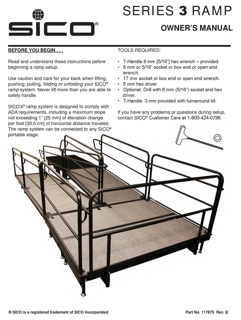
SICO 3 Series User manual

® SICO is a registered trademark of SICO Incorporated.
TRI-HEIGHT
STAGE SYSTEM
Series 3
Printed in USA (11-99) Part No. 111452 Rev. A
To avoid injury, read
and understand
these instructions
before you start to
set up the stage.
OWNER’S MANUAL: Instructions and Warnings
BEFORE YOU BEGIN... TOOLS REQUIRED
WARNING
zHex wrench (provided) to unlock decks for reversing
the surfaces -- if reversible decks were ordered.
zTwo 9/16-in. wrenches to attach hand rails to stair-
ways.
If you have any problems when installing,
contact SICO Customer Service at
1-800-328-6138.

INTRODUCTION
Stage Configurations
A Tri-Height Stage System consists of individual
4x8-ft or 6x8-ft stage sections that can be folded
for storage.
The stage sections are available in the following
height combinations:
z30 - 36 - 42 in. (762 - 914 - 1067 mm)
z24 - 30 - 36 in. (610 - 762 - 914 mm)
z24 - 32 in. (610 - 813 mm)
z18 - 24 - 30 in. (457 - 610 - 762 mm)
z16 - 24 in. (406 - 610 mm)
z12 - 18 in. (305 - 457 mm)
z8 in. (203 mm) nonadjustable
z6 in. (152 mm) nonadjustable
zOther combinations on special order
To set up a stage, you will:
1. Adjust the legs to match the desired height
of the stage.
2. Unfold individual sections.
3. If desired, reverse the deck surfaces (if
optional reversible decks were ordered).
4. Secure individual sections to each other.
5. Attach stairways, ramps, guard rails, table/
chair stops, backdrops, and closure draper-
ies.
These steps are explained in detail on the
following pages.
IMPORTANT: Construct the stage by starting in
one corner. Position the first stage section in
one of the two positions shown, so the three
unit-to-unit connector brackets face the remain-
der of the stage. Additional stage sections will
be hooked onto these brackets to secure the
sections together. Build the stage out from the
corner, positioning each section so its unit-to-
unit connectors are oriented the same as those
on the first unit.
Multiple Heights: If multiple heights will be
used in the same stage setup, start with the tall-
est units and work toward the lower units.
Position 1
Stage
Unit-to-Unit
Connector Brackets
Position 2
2

POSITIONING THE FIRST SECTION
NOTE: Adjustable-height stage sections
are shown in all illustrations.
1. Move the first section approximately to its
desired location.
CAUTION: When moving, push or pull from
the end of the folded unit. Pulling on the
crossbar along the side of the unit could un-
lock the stage and allow it to open. Pushing
on the side of the unit could cause it to tip
over.
Nonadjustable-Height Stages. Skip Steps
2 and 3, and go directly to Step 4.
2. Adjustable-Height Stages. Adjust the
height of the four end legs (refer to the illus-
trations):
a. On one side of the stage section, pull the
end leg lock crossbar out to its unlatched
position (refer to the upper illustration).
b. On one of the end legs, pull the lock
handle straight out to retract the leg lock
pin (refer to the middle illustration).
c. Move the leg extension in or out to get
the desired height.
d. Release the leg lock handle, and be sure
the leg lock pin engages in the hole in
the leg.
e. Repeat Steps 2b through 2d for the other
end leg on that side of the stage section.
f. Repeat Steps 2a through 2e on the other
side of the stage section.
3. Adjustable-Height Stages. Adjust the
height of the four foldout legs:
NOTE: The foldout legs must be used at all
stage heights.
a. Swing the leg out to a 90º angle with the
deck, as shown.
b. Pull the leg lock handle straight out to
retract the leg lock pin.
c. Move the leg extension in or out to get
the desired height.
d. Release the leg lock handle, and be sure
the leg lock pin engages in the hole in
the leg.
3
End Leg
Lock
Crossbar
End Leg
Adjustment
Foldout
Leg
Adjustment
Step 3a
Step 3b - 3d

POSITIONING THE FIRST SECTION -- continued
4. Adjustable-Height Stages. On one side of
the stage section, pull out on the end leg
lock crossbar.
Nonadjustable-Height Stages. Discon-
nect one end of the bungee cord and lower
the deck locking tube to the floor.
5. On the same side of the unit, grasp the
edge of the deck frame and the end leg lock
crossbar. Pull the deck toward you and
slowly lower it until the end legs touch the
floor.
6. In the same manner, pull down the other
side of the unit, and slowly lower it until the
end legs touch the floor.
Continue pulling the deck down until the
foldout legs on that side are also in contact
with the floor.
7. Go back to the first side of the unit, and pull
that side down until all four foldout legs and
all four end legs are in contact with the floor.
8. Move the stage into position (see IMPOR-
TANT note on page 2).
4

INSTALLING ADDITIONAL SECTIONS
REVERSING THE DECK SURFACE
1. Move a second frame unit next to the first
one.
2. Set up the second unit in the same way you
did the first one.
3. Lift the edge of the second unit’s deck onto
the unit-to-unit connector bracket(s) Aof the
first unit.
NOTE: If the second unit is set up at a
lower height than the first unit, hook the
edge of its deck onto the small brackets B
that are welded to the legs of the first unit
(instead of hooking it onto the deck brack-
ets A).
4. Repeat the above procedure for all remain-
ing sections.
Optional reversible decks are available for the
stage sections
To reverse these decks:.
1. Use the hex wrench supplied with the stage
system to remove the large socket-head
screw at each corner of the deck.
A spring will lift one corner of the deck out
of the frame so that it is easy to grasp.
2. Turn the deck over. Set the edge of the
deck that is opposite the spring into posi-
tion on the frame.
CAUTION: In the following step, work
slowly to avoid pinching fingers between the
deck and frame.
3. Grasp the corner of the deck where the
spring is located, and slowly lower the deck
onto the spring. When the spring is sup-
porting the deck weight, release the deck.
4. Reattach the deck to the frame using the
four large socket-head screws. Use the hex
wrench to tighten just until snug -- don’t
overtighten.
5. Repeat the procedure for the other decks to
be reversed.
IMPORTANT: The decks must be locked
with the four screws, or they may fall off
when the units are folded.
5
A
B

ATTACHING A RAMP
ATTACHING A THREE-HEIGHT STAIRWAY
NOTE: SICO ramps are provided in 6-ft or
8-ft (183 or 244 cm) section lengths, with an
incline of one in. per foot (83 cm per meter).
Detailed instructions for attaching a ramp to the
Tri-Height Stage are shipped with the ramp.
Follow those instructions, and abide by all local,
state, and federal regulations regarding ramp
design.
The same instructions include information on
installing SICO ramp guard rails, which are
designed for use by those in wheelchairs.
The Three-Height Stairway is adjustable to
three stage heights.
To change the steps to a higher setting:
1. Pull up on the bottom edge of the steps.
There is a height adjustment latch on each
side of the stairway: you will hear the
latches click each time they reach another
height setting.
2. When they are at the desired position, push
down on the steps to seat the stairway side
rails firmly into the appropriate notch of the
latches.
NOTE: Before the stairway is first used,
attach the two side rails as shown in the
illustrations. Use two 9/16-in. wrenches to
secure the rails with the screws and nylon-
insert lock nuts that are provided. Be sure
the rails are installed with their longer loops
at the high end of the stairway.
To transport the Three-Height Stairway, roll it on
its four casters. For easiest maneuvering, push
from the high end of the stairway.
Move the stairway to its desired location.
6

ATTACHING A THREE-HEIGHT STAIRWAY -- continued
To change the steps to a lower setting:
NOTE: Two people are required.
1. Simultaneously pull out on the latch handles
on each side of the stairway, and lower the
steps until the latches are in the appropriate
notch.
2. Release the latch handle. Check that the
stairway is stable.
To attach the stairway to the stage:
NOTE: Two people are required.
1. The stairway has two yellow bars extending
from the top step. Lift the high end of the
stairway and rest the yellow bars on the
deck.
2. Pull down on the ring to activate the spring-
loaded lock pin.
3. Push the stairway against the stage until the
lock pin releases and latches against the
inside of the stage frame.
4. Check to be sure the stairway is locked
firmly in place.
7
WARNING
Secure stairway to
stage to avoid
movement.
Failure to do so
could result in
serious injury.

ATTACHING A TWO-HEIGHT STAIRWAY
To transport the Two-Height Stairway, tip it to
the side as shown.
Move the stairway to its desired location.
The stairway is adjustable to either of two stage
heights by installing the lock pin assembly onto
the appropriate studs.
To attach the stairway to the stage:
1. The stairway has two yellow bars extending
from the top step. Lift the upper end of the
stairway and rest the yellow bars on the
deck.
2. Pull down on the ring to activate the spring-
loaded lock pin.
3. Push the stairway against the stage until
lock pin releases and latches against the
inside of the stage frame.
4. Check to be sure the stairway is locked
firmly in place.
8
WARNING
Secure stairway to
stage to avoid
movement.
Failure to do so
could result in
serious injury.
Lock Pin
Assembly

ATTACHING GUARD RAILS AND BACKDROP
Use platform guard rails in all Tri-Height
Stage setups. These rails are availabe in 3-, 4-,
6-, and 8-ft versions.
NOTE: Instructions on installing ramp guard
rails are shipped with the ramp. Flat sections of
ramps use the standard platform guard rails
shown here.
To install a platform guard rail:
1. Lift the rial into place so its jaws slip all the
way onto the edge of the deck.
To install a backdrop section:
Backdrop units install the same way as the guard
rails.
2. Securely clamp the rail onto the edge of the
deck, by turning the large yellow knobs coun-
terclockwise (as viewed from above).
3. Install the remaining rails in the same way.
WARNING
Attach guard rails to
platform to avoid
falls. Failure to do
so could result in
serious injury.
9

ATTACHING TABLE/CHAIR STOPS
Table/chair stops are available in 3-, 4-, 5-, 6-,
and 8-ft versions for locations where a platform
guard rail is not used (guard rails have a built-in
chair stop).
To install a table/chair stop, position it on the
edge of the deck as shown and firmly tighten the
large knob near each end.
1. Adjust the drapery length to match the stage
height. The hook Velcro®strip on the bottom
of the drapes can be mated with the loop
Velcro strips on the back of the drape.
2. Tri-Height stage sections are supplied with
a Velcro strip around the perimeter of the
deck. Attach drapery sections to this strip.
Overlap adjacent sections as shown in the
inset drawing.
The drape can be installed behind stair-
ways, by looping it over the posts below the
top step.
10
ATTACHING CLOSURE DRAPERY

DISASSEMBLING THE STAGE
Disassemble the stage by reversing the setup
procedure.
1. Remove any backdrops and closure draper-
ies.
2. Remove the guard rails and table/chair
stops.
3. Remove the stairway(s) by pulling down on
the rings to release the deck lock pin on
each side (see Page 7 or 8).
4. Fold each stage section for transport and
storage:
a. Lift one side of the section to its upright
(folded) position. It usually works best,
especially at higher setup heights, to pull
the stage section toward you as you lift
on the edge of the deck. For added lev-
erage, if necessary to force all four cast-
ers to the floor, lift on the foldout leg.
IMPORTANT: Lift on the bottom edge of
the deck -- do not let your hands get over
the top edge of the deck when folding.
b. Adjustable-Height Stages. Lock that
same side of the stage section in the
folded position by pushng in on the end
legs or cross tube. If the unit was used
at the 40- or 42-in. (1016- or 1067-mm)
height, adjust the end legs to a shorter
position.
Nonadjustable-Height Stages. Rotate
the deck lock tube until it contacts the
deck just under the cross tube.
c. Repeat Steps 4a and 4b on the other
side of the unit.
Nonadjustable-Height Stages. Hook
the bungee cord hook into the hole on
the opposite side of the stage.
d. Fold the four foldout legs in against the
deck.
11
CAUTION
When folding the
unit, don’t put
your fingers
between the decks.

To receive assistance for:
- Selecting replacement parts / decals
- Repairing the product
- Adjusting and operating the product
- Obtaining On-line assistance
TELEPHONE: 1-800-424-0796
FAX: (952) 829-5141
WEB SITE: WWW.SICOINC.COM
SICO AMERICA INC.
7525 Cahill Road
Minneapolis, MN 55439 USA 12
Other manuals for 3 Series
1
Other SICO Lifting System manuals
Popular Lifting System manuals by other brands
TradeQuip
TradeQuip 2002T owner's manual
Tractel
Tractel magfor II100 Instructions for use
TOOLCRAFT
TOOLCRAFT 2576671 operating instructions
QSP
QSP LM-200-R2 Operation instructions
Aqua Creek Products
Aqua Creek Products F-03EZPLNA Installation, assembly and operation manual

Blue Giant
Blue Giant H7012 Installation & technical manual
