Blue Giant EPJ-60R User manual

OWNER’S MANUAL
EPJ-60R RIDER PALLET LIFT TRUCK
WARNING
Do not operate or service this product unless you have
read and fully understand the entire contents of this
manual. Failure to do so may result in property damage,
bodily injury or death.
ISSUE DATE: MAY 5, 2020 REV.0 (PART # 038-xxxxE)

WARNING
Do not operate this truck unless you have been autho-
rized and trained to do so, and have read all warnings
and instructions in Operator’s Manual and on this
truck.
Do not operate this truck until you have checked its
condition. Give special attention to tires, horn, battery,
controller, lift system, brakes, steering mechanism,
guards and safety devices.
Operate truck only from designated operating position.
Do not carry passengers. Keep feet clear of truck and
wear foot protection.
Observe applicable traffic regulations. Yield right of
way to pedestrians. Slow down and sound horn at
cross aisles and wherever vision is obstructed.
Start, stop, travel, steer and brake smoothly. Slow
down for turns and on uneven or slippery surfaces that
could cause truck to slide or overturn. Use special
care when traveling without load as the risk of overturn
may be greater.
Always look in direction of travel. Keep a clear view,
and when load interferes with visibility, travel with load
trailing.
Use special care when operating on ramps travel
slowly, and do not angle or turn. Travel with load
downhill.
Do not handle loads which are higher than the load
backrest or load backrest extension unless load is
secured so that no part of it could fall backward.
Before lifting, be sure load is centered, forks are com-
pletely under load, and load is as far back as possible
against load backrest.
When leaving truck, neutralize travel control, fully
lower lifting mechanism and set brake. When leaving
truck unattended, also shut off power.

TABLE OF CONTENTS
Section Page Section Page
1 DESCRIPTION............................................................1-1
1-1. INTRODUCTION..............................................1-1
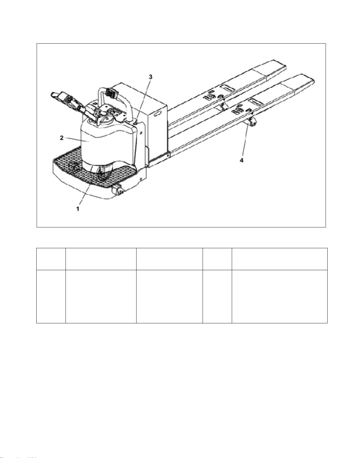
1-2. GENERAL DESCRIPTION...............................1-1
1-3. SAFETY FEATURES. ......................................1-2
2 OPERATION ...............................................................2-1
2-1. GENERAL. .......................................................2-1
2-2. OPERATING PRECAUTIONS. ........................2-1
2-3. BEFORE OPERATION.....................................2-1
2-4. TRAVEL. ..........................................................2-4
2-4.1. BRAKE.............................................................2-4
2-4.2. TRAVEL ...........................................................2-4
2-4.3. BELLY-BUTTON SWITCH...............................2-4
2-5. STEERING ARM GAS SPRING.......................2-5
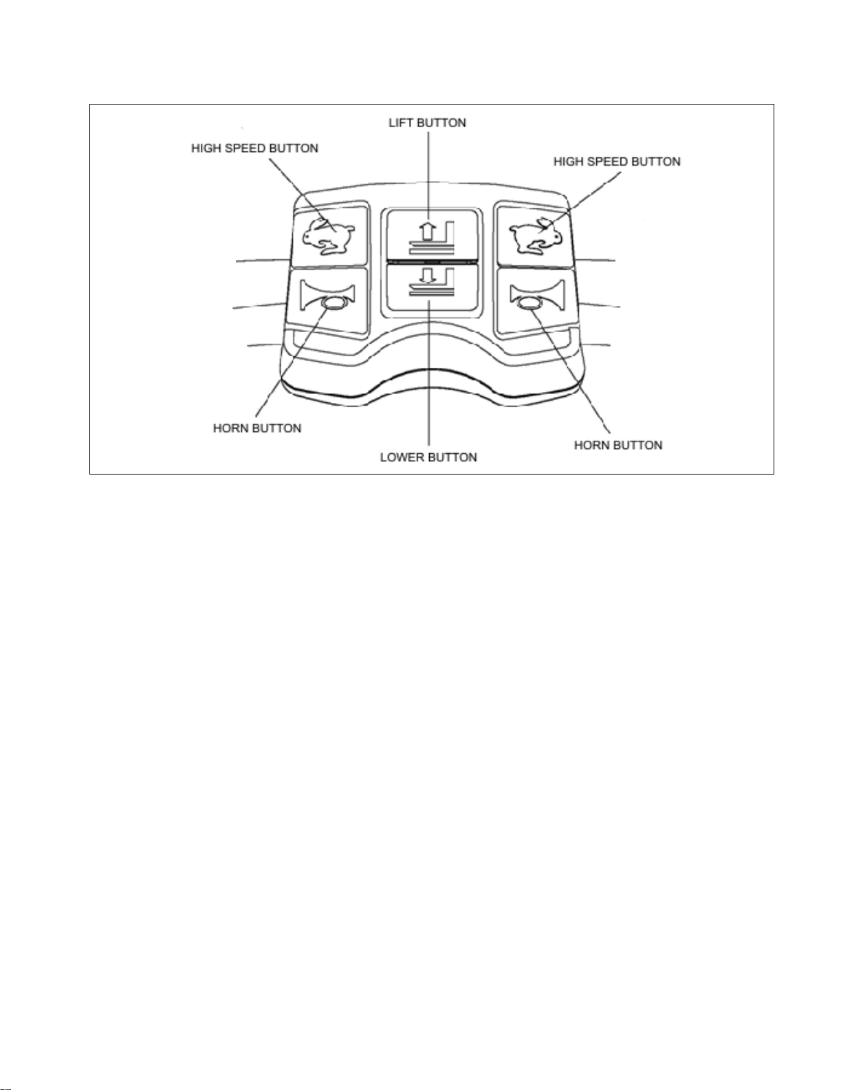
2-6. LIFT AND LOWER CONTROLS. .....................2-5
2-7. LOADING AND UNLOADING. .........................2-5
2-8. PARKING. ........................................................2-5
3 PLANNED MAINTENANCE ........................................3-1
3-1. GENERAL. .......................................................3-1
3-2. MONTHLY AND QUARTERLY CHECKS........3-1
3-3. BATTERY CARE.............................................3-1
3-3.1. GENERAL ........................................................3-1
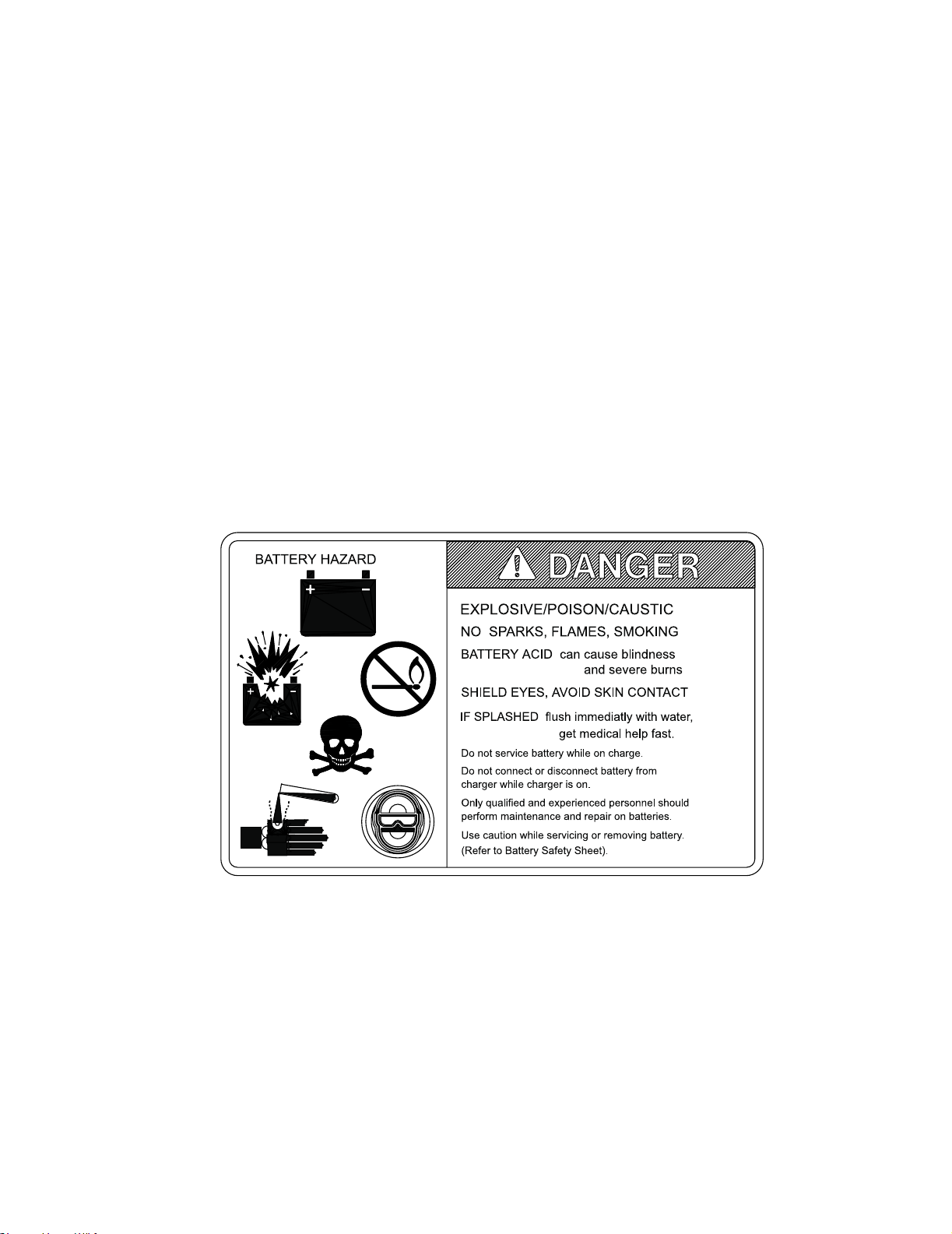
3-3.2. SAFETY RULES ..............................................3-2
3-3.3. BATTERY CARE AND CHARGING.................3-2
3-3.4. BATTERY CLEANING......................................3-2
3-3.5. MAINTENANCE FREE BATTERIES................3-3
3-4. CHARGING BATTERIES.................................3-3
3-5. LUBRICATION. ................................................3-4
4 TROUBLESHOOTING ................................................4-1
4-1. GENERAL ........................................................4-1
4-2. CONTROLLER TROUBLESHOOTING............4-4
4-2.1. ZAPI CAN CONSOLE KIT................................4-4
4-2.2. DIAGNOSTIC HISTORY..................................4-6
4-2.3. ADJUISTMENT. ...............................................4-6
5 STEERING ARM, CONTROL HEAD AND
COMPARTMENT ........................................................5-1
5-1. CONTROL HEAD.............................................5-1
5-1.1. COVER REMOVAL..........................................5-1
5-1.2. COVER INSTALLATION..................................5-2
5-1.3. CONTROL HEAD REMOVAL ..........................5-3
5-1.4. CONTROL HEAD INSTALLATION ..................5-3
5-1.5. BELLY-BUTTON SWITCH REPLACEMENT...5-3
5-1.6. HORN, LIFT AND LOWER SWITCH
REPLACEMENT...............................................5-3
5-1.7. SPEED POTENTIOMETER REPLACEMENT. 5-3
5-2. STEERING ARM..............................................5-3
5-2.1. RETURN SPRING REPLACEMENT................5-3
5-2.2. STEERING ARM REMOVAL............................5-4
5-2.3. STEERING ARM INSTALLATION....................5-4
5-3. COMPARTMENT COVERS.............................5-4
5-3.1. REMOVAL........................................................5-4
5-3.2. INSTALLATION................................................5-4
6 BRAKE SERVICING................................................... 6-1
6-1. BRAKE............................................................. 6-1
6-1.1. AIR GAP ADJUSTMENT................................. 6-1
6-1.2. STOPPING DISTANCE ADJUSTMENT.......... 6-2
6-1.3. BRAKE ASSEMBLY REPLACEMENT ............ 6-2
7 TRANSMISSION, DRIVE WHEEL, LOAD WHEEL.... 7-1
7-1. DRIVE WHEEL................................................ 7-1
7-2. TRANSMISSION. ............................................ 7-1
7-3. LOAD WHEEL. ................................................ 7-3
7-3.1. REMOVAL ....................................................... 7-3
7-3.2. REPAIR ........................................................... 7-3
7-3.3. LOAD WHEEL INSTALLATION....................... 7-3
7-4. CASTERS........................................................ 7-3
8 ELEVATION SYSTEM SERVICING........................... 8-1
8-1. LIFT LINKAGE................................................. 8-1
8-1.1. REMOVAL ....................................................... 8-1
8-1.2. REPAIR ........................................................... 8-1
8-1.3. INSTALLATION ............................................... 8-1
9 HYDRAULIC SYSTEM SERVICING........................... 9-1
9-1. LINES AND FITTINGS .................................... 9-1
9-2. HYDRAULIC PUMP, MOTOR, AND
RESERVOIR ASSY......................................... 9-1
9-2.1. REMOVAL ....................................................... 9-1
9-2.2. DISASSEMBLY AND REASSEMBLY ............. 9-3
9-2.3. INSTALLATION ............................................... 9-3
9-2.4. LIFT CYLINDER .............................................. 9-3
10 ELECTRICAL COMPONENTS................................. 10-1
10-1. ELECTRICAL CONTROL PANEL ................. 10-1
10-1.1.MAINTENANCE............................................. 10-1
10-1.2.CLEANING .................................................... 10-1
10-1.3.PANEL REMOVAL. ....................................... 10-1
10-1.4.PANEL DISASSEMBLY................................. 10-1
10-1.5.PANEL INSTALLATION. ............................... 10-1
10-2. HORN REPLACEMENT ................................ 10-4
10-3. PUMP MOTOR.............................................. 10-5
10-4. DRIVE MOTOR. ............................................ 10-5
10-4.1.MOTOR REMOVAL....................................... 10-5
10-4.2.MOTOR INSTALLATION............................... 10-5
10-5. LIFT LIMIT SWITCH...................................... 10-5
10-5.1.REPLACEMENT............................................ 10-5
10-5.2.ADJUSTMENT............................................... 10-5
10-6. DEADMAN SWITCH...................................... 10-6
10-6.1.REPLACEMENT............................................ 10-6
11 OPTIONAL EQUIPMENT ......................................... 11-1
11-1. LOAD BACKREST......................................... 11-1
12 ILLUSTRATED PARTS BREAKDOWN.................... 12-1

TABLE OF CONTENTS - Continued
LIST OF ILLUSTRATIONS
Figure Page Figure Page
1-1 NAME PLATE ..................................................... 1-1
1-2 EPJ-60R LIFT TRUCK .............................................. 1-1
2-1 SAMPLE OF OPERATOR CHECK LIST............ 2-3
2-2 BRAKE ACTUATION.......................................... 2-4
2-3 CONTROL HEAD................................................ 2-4
2-4 GRAB BAR.......................................................... 2-5
3-1 LUBRICATION DIAGRAM.................................. 3-5
4-1 CONNECTING THE HANDSET.......................... 4-4
4-2 ZAPI PC CAN CONSOLE SCREEN................... 4-4
4-3 DEVICE CONFIGURATION SCREEN................ 4-4
4-4 CONFIGURATION CAN SCREEN ..................... 4-4
4-5 CAN HARDWARE SCREEN............................... 4-5
4-6 CONFIGURATION CAN SCREEN ..................... 4-5
4-7 ZAPI PC CAN CONSOLE SCREEN................... 4-5
4-8 SET NODE SCREEN.......................................... 4-5
4-9 ZAPI PC CAN CONSOLE SCREEN................... 4-5
4-10 PASSWORD SCREEN....................................... 4-5
4-11 ZAPI PC CAN CONSOLE SCREEN................... 4-6
4-12 ZAPI PC CAN CONSOLE SCREEN................... 4-6
4-13 ALARM LOGBOOK SCREEN............................. 4-6
4-14 ZAPI PC CAN CONSOLE SCREEN................... 4-6
4-15 PARAMETERS SCREEN ................................... 4-7
5-1 STEERING ARM................................................. 5-1
5-2 CONTROL HEAD................................................ 5-2
5-3 STEERING SYSTEM.......................................... 5-5
6-1 BRAKE ASSEMBLY............................................ 6-1
7-1 TRANSMISSION, MOTOR, BRAKE ASSEMBLY 7-1
7-2 DRIVE SYSTEM ................................................. 7-2
8-1 FRAME................................................................ 8-2
8-2 LIFT LINKAGE..................................................... 8-3
9-1 HYDRAULIC SYSTEM........................................ 9-2
9-2 PUMP & MOTOR ASSY...................................... 9-4
9-3 LIFT CYLINDER.................................................. 9-5
10-1 SCREEN 11....................................................... 10-1
10-2 ELECTRICAL SYSTEM..................................... 10-2
10-3 ELECTRICAL PANEL........................................ 10-3
10-4 SCREEN 11....................................................... 10-4
10-5 BRAKE ACTUATION......................................... 10-4
10-6 TRANSMISSION, MOTOR, BRAKE
ASSEMBLY....................................................... 10-5
12-1 STEERING SYSTEM ........................................ 12-2
12-2 STEERING ARM............................................... 12-4
12-3 CONTROL HEAD.............................................. 12-6
12-4 GRAB BAR ASSEMBLY.................................... 12-8
12-5 DRIVE SYSTEM.............................................. 12-10
12-6 TRANSMISSION, MOTOR, BRAKE
ASSEMBLY..................................................... 12-12
12-7 FRAME............................................................ 12-14
12-8 LIFT LINKAGE................................................. 12-16
12-9 CASTER WHEEL............................................ 12-18
12-10 HYDRAULIC SYSTEM.................................... 12-20
12-11 PUMP & MOTOR ASSY.................................. 12-22
12-12 LIFT CYLINDER.............................................. 12-24
12-13 ELECTRICAL SYSTEM................................... 12-26
12-14 ELECTRICAL PANEL...................................... 12-28
12-15 WIRING HARNESS......................................... 12-30
12-16 WIRING CABLES............................................ 12-32
LIST OF TABLES
Table Page Table Page
2-1 OPERATOR CHECKS......................................... 2-2
3-1 MONTHLY AND QUARTERLY INSPECTION
AND SERVICE CHART ....................................... 3-1
3-2 RECOMMENDED LUBRICANTS ........................ 3-4
3-3 LUBRICATION CHART........................................ 3-5
4-1 TROUBLESHOOTING CHART............................4-1
4-2 ADJUSTMENT SETTINGS ..................................4-7
4-3 FACTORY SETTING............................................4-7

SECTION 1
DESCRIPTION
1-1. INTRODUCTION.
This publication describes the 24 volt transistor
EPJ-60R lift truck distributed by Blue Giant.Included
are oper-ating instructions, planned maintenance
instructions, lubrication procedures, corrective
maintenance proce-dures and a complete parts list
with part location illus-trations.
Users shall comply with all requirements indicated in
applicable OSHA standards and current edition of
A.N.S.I. B56.1 Part II. By following these requirements
and the recommendations contained in this manual,
you will receive many years of dependable service
from your EPJ-60R lift truck.
1-2. GENERAL DESCRIPTION.
The self-propelled WPT 60 truck, Figure 1-2, lifts and
transports payloads up to 6000 pounds on rigid forks.
The truck can be operated from the walking position
using the control head or from the riding position using
the grab bar.
The battery powered lift truck is quiet and without
exhaust fumes.
The reversible AC motor propels the lift truck in for-
ward or reverse direction throughout the available
speed range. The EPJ-60R lift truck can be driven
with forks raised or lowered. The lift truck must be
pro-tected from the elements.
The model number will be found on the name plate
(Figure 1-1) along with the serial number, lifting capac-
ity, and load center. Figure 1-2 shows the locations of
the truck’s main components and controls.
Figure 1-1 Name Plate
Figure 1-2 EPJ-60R Lift Truck
R6209
COMPLIES WITH THE APPLICABLE REQUIRE-COMPLIES WITH THE APPLICABLE REQUIRE-
MENTS OF ANSI B56.1 AND OSHA STANDARDSMENTS OF ANSI B56.1 AND OSHA STANDARDS
AUSTRALIAN PATENT NO. 537,987AUSTRALIAN PATENT NO. 537,987
U.S. PATENT NO. 4,444,284U.S. PATENT NO. 4,444,284
TRUCK
TYPE
MODEL NO. SERIAL NO.
VOLTAGE
BATTERY
TYPETYPE CERTIFIEDCERTIFIED
MAX CAP LB/MAX CAP LB/ LOAD CTR IN/LOAD CTR IN/ LIFT HGT IN/
LOAD CTR IN/LOAD CTR IN/ LIFT HGT IN/ALT CAP LB/
BATTERY MIN WT LB/BATTERY MIN WT LB/TRUCK WT LESS BATTERY LB/TRUCK WT LESS BATTERY LB/
BATTERY MAX WT LB/BATTERY MAX WT LB/TRUCK WT WITH BATTERY LB/TRUCK WT WITH BATTERY LB/
KG MM MM
MM MMKG
KGKG
KGKG
R6800A

1-3. SAFETY FEATURES.
The EPJ-60R is designed and engineered to provide
max-imum safety for operator and payload. Some of
the safety features incorporated into the design are:
• Dead-man brake to apply the brake and cut off drive
power when the steering arm is released.
• Belly-button switch to reverse truck should the oper-
ator accidentally pin himself against a wall or
obstruction when backing up in slow speed.
• All control functions automatically return to “OFF”
when released.
• Externally accessible quick-disconnect battery plug
within operator's reach.
• Separately fused control circuits and power circuits.
• Readily accessible horn button.
• Handle to provide a firm hand hold for operator.
• Flow control valve regulates maximum lowering
speed within prescribed limits.
• Relief valve maintains hydraulic pressure within pre-
scribed limits.
• High visibility color scheme of truck provides visual
alert of truck’s presence.
• Battery Indicator
•Casters

SECTION 2
OPERATION
2-1. GENERAL.
This section gives detailed operating instructions for
the EPJ-60R lift truck. The instructions are divided into
the various phases of operations, such as operating
lift, driving, and stopping. Routine precautions
are included for safe operation.
2-2. OPERATING PRECAUTIONS.
WARNING: Improper operation of the lift truck may
result in operator injury, or load and/or lift
truck damage. Observe the following
precautions when operating the EPJ-60R
lift truck.
The following safety precautions must be adhered to
at all times.
• Do not operate this truck unless you have been
trained and authorized to do so and have read all
warnings and instructions in this manual and on the
truck.
• All warnings and instructions must be read and
understood before using the equipment.
• Equipment must be inspected by a qualified person
on a regular basis.
• Do not operate this truck until you have checked its
condition. Give special attention to Tires, Horn, Bat-
teries, Controller, Lift System, Brakes, Steering
Mechanism, Guards and Safety Devices
• Operate truck only from designated operation posi-
tion. Wear foot protection. Do not carry passengers.
• Observe applicable traffic regulations. Yield right of
way to pedestrians. Slow down and sound horn at
cross aisles and wherever vision is obstructed.
• Start, stop, travel, steer and brake smoothly. Slow
down for turns and on uneven or slippery surfaces
that could cause truck to slide or overturn. Use spe-
cial care when traveling without load as the risk of
overturn may be greater.
• Always look in direction of travel. Keep a clear view,
and when load interferes with visibility, travel with
load or lifting mechanism trailing.
• Do not overload truck. Check nameplate for load
weight and load center information.
• Before lifting, be sure load is centered, forks are
completely under load, and load is as far back as
possible against load backrest.
• Do not handle loads which are higher than the load
backrest unless load is secured so that no part of it
could fall backward.
• When leaving truck, neutralize travel control. Fully
lower lifting mechanism and set brake. When leaving
truck unattended, turn off key switch and disconnect
switch, remove key and disconnect battery.
2-3. BEFORE OPERATION
Table 2-1 covers important inspection points on the
EPJ-60R lift truck which should be checked prior to
opera-tion. Depending on use, some trucks may
require additional checks.
Figure 2-1 shows a sample format for an Operator
Checklist, which can be modified as necessary to fit
your operation.
WARNING: Periodic maintenance of thistruck by a
QUALIFIED TECHNICIAN is required.
CAUTION: A QUALIFIED SERVICE TECHNICIAN
should check the truck monthly for
proper lubrication, proper fluid levels,
brake maintenance, motor maintenance
and other areas specified in the SEC-
TION 3.
WARNING: If the truck is found to be unsafe and in
need of repair, or contributes to an
unsafe condition, report it immediately to
the designated authority. Do not operate
it until it has been restored to a safe
operating condition. Do not make any
unauthorized repairs or adjustments. All
service must be performed by a qualified
maintenance technician.

Table 2-1 Operator Checks
ITEM PROCEDURE
Transmission
and hydraulic
systems.
Check for signs of fluid leakage.
Forks Check for cracks and damage.
Safety signs Check that warning labels,
nameplate, etc., are in good
condition and legible.
Horn Check that horn sounds when
operated.
Steering Check for binding or looseness in
steering arm when steering.
Travel controls Check that speed controls on
control head operate in all
speed ranges in forward and
reverse and that belly button
switch functions.
Wheels Check drive wheel for cracks or
damage. Move truck to check
load for freedom of rotation.
Hydraulic
controls Check operation of lift and lower
to their maximum positions.
Brakes Check that brakes actuate when
steering arm is raised to upright
position, and when lowered to
horizontal position.
Deadman/
Parking brake Check that steering arm raises to
upright position when released
and brake applies.
Battery
disconnect Check that battery can be
disconnected and recon-
nected. Check for connector
damage.
Battery charge Check the battery indicator.
ITEM PROCEDURE

Figure 2-1 Sample of Operator Check List
R6479
Electric Truck
Daily Operator Check-Off List
Date Operator
Truck No. Model No.
Dept.
Check
Tires
Load Wheels
Horn
Lift Lower Control
Need MaintenanceO.K. ( )
Shift
Hour Meter
Reading Drive Hoist
Attachment Operation
Forward & Reverse Controls
Steering
Brakes
Hydraulic Leaks, Cylinders,
Valves, Hoses, Etc.

2-4. TRAVEL.
2-4.1. Brake
The brake is fully applied by lowering or raising the
steering arm. (See Figure 2-2) All travel control power
is shut off when the brake is engaged. When the steer-
ing arm is in the upright position, the brake acts as a
parking brake. Deadman braking occurs when the
handle is released and spring action raises steering
arm to the upright position.
2-4.2. Travel
Move the control arm to the travel position. The speed
control (See Figure 2-3) located on each side of the
control head provides fingertip control for driving the
truck. Rotate the control in the direction you want to
travel. The farther you rotate the control from the neu-
tral position, the faster the truck will travel.
2-4.3. Belly-Button Switch
The belly-button switch (Figure 2-3) minimizes the
possibility of the driver being pinned by the steering
arm while driving the lift truck in the walking position. If
the switch presses against the operator while the lift
truck is being driven toward the operator, the switch
changes the direction of the lift truck.
In an emergency, pull out battery connector, all electri-
cal functions are cut out and the truck automatically
brakes.
Figure 2-2 Brake Actuation
Figure 2-3 Control Head
R6802
R6801

Figure 2-4 Grab Bar
2-5. STEERING ARM GAS SPRING.
The steering arm gas spring automatically raises the
steering arm to the upright position when the
steering arm is released. If the steering arm does
not return fully, the steering arm gas spring
requires replace-ment. Return truck to maintenance
for repair.
2-6. LIFT AND LOWER CONTROLS.
Lift/Lower Control buttons are located on the steering
control head. (Figure 2-3) and the grab bar (Figure
2-4).
To lift forks, push in either LIFT button and hold until
forks reach desired height. To lower forks, push in
either LOWER button and hold until forks descend to
desired height.
2-7. LOADING AND UNLOADING.
1. Move truck to location where load is to be picked
up.
2. Move the truck into position so forks are within
pallet or skid, and the load is centered over the
forks and as far back as possible.
3. Raise forks to lift load.
4. Drive to area where load is to be placed.
5. Move truck to align load with its new position.
6. Lower the load until it rests squarely in place and
the forks are free.
7. Slowly move the truck out from under the load.
2-8. PARKING.
When finished with moving loads, return the truck to its
maintenance or storage area. Turn off the key switch
and disconnect the batteries. Charge batteries as nec-
essary. Refer to battery care instructions, SECTION 3.
R6803

NOTES

SECTION 3
PLANNED MAINTENANCE
3-1. GENERAL.
Planned maintenance consists of periodic visual and
operational checks, parts inspection, lubrication, and
scheduled maintenance designed to prevent or dis-
cover malfunctions and defective parts. The operator
performs the checks in SECTION 2, and refers any
required servicing to a qualified maintenance techni-
cian who performs the scheduled maintenance and
any required servicing.
3-2. MONTHLY AND QUARTERLY CHECKS.
Table 3-1 is a monthly and quarterly inspection and
service chart based on normal usage of equipment
eight hours per day, five days per week. If the lift truck
is used in excess of forty hours per week, the fre-
quency of inspection and service should be increased
accordingly. These procedures must be performed by
a qualified service technician or your Blue Giant Ser-
vice Representative.
3-3. BATTERY CARE.
3-3.1. General
The EPJ-60R may be equipped with maintenance
free or industrial wet cell batteries.
The care and maintenance of the battery is very
important to obtain efficient truck operation and maxi-
mum battery life.
CAUTION: Gases produced by a battery can be
explosive. Do not smoke, use an open
flame, create an arc or sparks in the
vicinity of the battery. Ventilate an
enclosed area well when charging.
CAUTION: Batteries contain sulfuric acid which may
cause severe burns. Avoid contact with
eyes, skin or clothing. In case of contact,
flush immediately and thoroughly with
clean water. Obtain medical attention
when eyes are affected. A baking soda
solution (one pound to one gallon of
water) applied to spilled acid until bub-
bling stops, neutralizes the acid for safe
handing and disposal.
Leakage voltage from battery terminals to battery case
can cause misleading trouble symptoms with the truck
electrical system. Since components of the truck elec-
trical system are insulated from truck frame, leakage
voltage will not normally affect truck operation unless a
short circuit or breakdown of circuit wire insulation to
truck frame occurs.
A voltage check from battery connector terminal to
battery case should indicate near zero volts. Typically,
however, the sum of the voltages at both terminals will
equal battery volts. This leakage voltage will discharge
the battery. As battery cleanliness deteriorates, the
usable charge of the battery decreases due to this self
discharge.
Table 3-1 Monthly and Quarterly Inspection and Service Chart
VISUAL CHECKS
INTERVAL INSPECTION OR SERVICE
Monthly Check electrical brake for proper operation.
Monthly Check load wheels for wear. A poly load wheel must be replaced if worn to within 1/16 inch
of hub. Check for separation from hub.
Monthly Check drive wheel for wear. A poly drive wheel must be replaced if worn to within 3/4 inch
of hub. Check for separation from hub.
Monthly Inspect wiring for loose connections and damaged insulation.
Monthly Inspect contactors for proper operation.
Monthly Check deadman brake switch for proper operation.
Quarterly Check lift cylinder for leakage.
Quarterly Check for excessive jerking of steering arm when stopping or starting.

Although a leakage voltage reading of zero volts may
not be possible, a cleaner battery will have more
usable charge for truck operation and not affect opera-
tion of electronic devices on the unit.
3-3.2. Safety Rules
• Wear protective clothing, such as rubber apron,
gloves, boots and goggles when performing any
maintenance on batteries. Do not allow electrolyte to
come in contact with eyes, skin, clothing or floor. If
electrolyte comes in contact with eyes, flush immedi-
ately and thoroughly with clean water. Obtain medi-
cal attention immediately. Should electrolyte be
spilled on skin, rinse promptly with clean water and
wash with soap. A baking soda solution (one pound
to one gallon of water) will neutralize acid spilled on
clothing, floor or any other surface. Apply solution
until bubbing stops and rinse with clean water.
• If truck is equipped with wet cell batteries, keep vent
plugs firmly in place at all times except when adding
water or taking hydrometer readings. Do not allow
dirt, cleaning solution or other foreign material to
enter cells. Impurities in electrolyte has a neutraliz-
ing effect reducing available charge.
• Do not bring any type of flame, spark, etc., near the
battery. Gas formed while the battery is charging, is
highly explosive. This gas remains in cell long after
charging has stopped.
• Do not lay metallic or conductive objects on battery.
Arcing will result.
• Do not touch non-insulated parts of DC output con-
nector or battery terminals to avoid possible electri-
cal shock.
• De-energize all AC and DC power connections
before servicing battery.
• Do not charge a frozen battery.
• Do not use charger if it has been dropped or other-
wise damaged.
3-3.3. Battery Care and Charging
CAUTION: Never smoke or bring open flame near
the battery. Gas formed during charging
is highly explosive and can cause seri-
ous injury.
1. Charge the battery only in areas designated for
that use.
2. Make certain the charger being used matches the
voltage and amperage of the truck battery.
3. Before disconnecting or connecting batteries to a
charger, make sure the charger is “OFF”. If an
attempt is made to do this while the charger is
“ON”, serious injury to you, the battery and the
charger could result.
4. Before connecting the battery cable to the trucks
receptacle, make sure the key switch is off. The
battery cable must be fully connected before the
truck is used. If the plug is not making good con-
tact, heat will weld the two parts of the battery
connector together, making it difficult to remove
and necessary to replace.
5. Battery terminals should be checked and cleaned
of corrosion regularly. Good battery terminal con-
tact is essential not only for operation, but also for
proper charging of the battery.
6. The charging requirements will vary depending on
the use of the truck. The battery should be given
as equalizing charge on a weekly basis. This
charge should normally be an additional three
hours at the finish rate.
7. Make certain battery used meets weight and size
requirements of truck. NEVER operate truck with
an undersized battery.
3-3.4. Battery Cleaning
Always keep vent plugs tightly in place when cleaning
battery. When properly watered and charged, the bat-
tery will remain clean and dry. All that is necessary is
to brush or blow off any dust or dirt that may accumu-
late on them. However, if electrolyte is spilled or over-
flows from a cell, it should be neutralized with a
solution of baking soda and water, brushing the soda
solution beneath the connectors and removing grime
from the covers. Then rinse the battery with cool water
from a low pressure supply to remove the soda and
loosen dirt. If batteries stay wet consistently, they may
be either overcharged or over filled. This condition
should be investigated and corrected.

3-3.5. MAINTENANCE FREE BATTERIES
Some trucks may be equipped with maintenance free
batteries. These batteries are completely sealed, will
not require any watering and have a full 80% dis-
charge available.
Sealed Maintenance Free batteries contain a pressure
release valve and under normal operating conditions
do not require any special ventilation.
CAUTION: Do not try to open this battery or remove
the pressure release valve.
Only under severe overcharging, such as connected
to an improperly sized charger, will any significant
amount of gasses be released from the battery. Also,
being a valve regulated battery, it never requires
watering.
3-4. CHARGING BATTERIES
Charging requirements will vary depending on depth
of discharge and temperature. Follow safety rules
when placing a battery on charge.
Proceed as follows:
1. Park truck at charging station with carriage low-
ered and turn the key switch off.
2. Check the condition of the AC cord, the battery
connector and battery cables. If there are any
cuts in the cable, any exposed wires, loose plugs
or connectors, DO NOT attempt to charge the
batteries. Contact appropriate personnel for
repairs to be made.
3. Disconnect the batteries from the truck and con-
nect the batteries to the charger. Make sure con-
nectors are mated properly.
4. Connect the charger to the appropriate power
supply.
5. Follow the instructions for the charger being used.

3-5. LUBRICATION.
Refer to Table 3-2 for the recommended types of
grease and oil. Table 3-3 in conjunction with Figure 3-
1identifies the items requiring lubrication.
Table 3-2 Recommended Lubricants
(See Table 3-3 for Application)
No. 1 Transmission oil—EP SAE 80W-90
Transmission oil—EP SAE 10W-30 (Note)
No. 2 Grease—Lithium base, general purpose.
No. 3 Hydraulic oil-Heavy duty with a viscosity of
150 SUS foam suppressing agent and
rust and oxidation inhibitors
Hydraulic oil-Heavy duty with a viscosity of
100 SUS foam suppressing agent and
rust and oxidation inhibitors (Note)
No. 4 SAE 30 or 40 Engine lubricating oil
NOTE: USED ON COLD CONDITIONED TRUCKS

Figure 3-1 Lubrication Diagram
Table 3-3 Lubrication Chart
FIG 3-2
INDEX
NO.
LOCATION METHOD OF
APPLICATION
TYPE
(Table
3-3)
APPLICATION
OF
LUBRICANT
1Transmission
Capacity 2 pints Can No. 1 Fill to level plug opening
2 Hydraulic Reservoir
Capacity-1 quarts Can No. 3 With lift carriage fully lowered, fill
reservoir with hydraulic oil to 1
inch below opening
3 Lift Linkage Fittings Gun No. 2 Pressure lubricate.
4 Lift Linkage Fittings* Gun No. 2 Pressure lubricate.
* Raise lift carriage to gain access to grease fittings.
R6805

NOTES

SECTION 4
TROUBLESHOOTING
4-1. GENERAL
Use Table 4-1 as a guide to determine possible
causes of trouble. The table is divided into five main
categories: Truck and Hydraulic System Will Not
Operate: Truck Does Not Operate Forward or
Reverse: Trouble With Braking: Trouble With Lifting Or
Lowering, and Miscellaneous malfunctions.
Table 4-1 Troubleshooting Chart
MALFUNCTION PROBABLE CAUSE CORRECTIVE ACTION
TRUCK AND HYDRAULIC
SYSTEM WILL NOT OPERATE
Truck will not travel nor will lift sys-
tem operate. a. Fuses (7, Figure 12-14) blown. Check fuses and replace if
necessary.
b. Battery dead or disconnected. Check battery quick-disconnect
plug and check battery voltage.
c. Keyswitch (13, Figure 12-13)
defective. Bypass keyswitch to determine if it
is malfunctioning.
d. Defective wiring. Check for open circuit. Repair as
required.
TRUCK DOES NOT OPERATE
FORWARD OR REVERSE
Truck does not travel forward or
reverse. All other functions oper-
ate normally.
a. Check all wiring. A loose con-
nection may be the cause of
malfunction.
Tighten all loose connections
before further troubleshooting.
b. Defective deadman switch (30,
Figure 12-2). Check and replace switch if
defective.
c. Defective main contactor (15,
Figure 12-14). Check for proper operation and
replace if necessary.
d. Defective potentiometer (10,
Figure 12-3). Check and replace potentiometer
if defective.
Truck travels forward but not in
reverse. Defective potentiometer (10, Fig-
ure 12-3) in control head. Check and replace potentiometer
if defective.
Truck travels reverse but not in
forward. Defective potentiometer (10, Fig-
ure 12-3) in control head. Check and replace potentiometer
if defective.
Truck travels forward and in
reverse at lower speeds; will not
travel at high speed.
Defective potentiometer (10, Fig-
ure 12-3) in control head. Check and replace potentiometer
if defective.
TROUBLE WITH BRAKING
Truck does not slow with brake, or
brake does not engage. a. Defective deadman switch (29,
Figure 12-2). Check deadman switch for
continuity. If none found when
the control arm is in the brake
position, replace switch.
b. Defective electric brake (49,
Figure 12-6). Adjust or replace brake.

Table 4-1 Troubleshooting Chart - Continued
MALFUNCTION PROBABLE CAUSE CORRECTIVE ACTION
TROUBLE WITH BRAKING -
Continued
Brake will not release. a. Air gap more than 0.01 in
(0.25mm). Adjust
b. Brake temperature above
281° F (140°C). Allow to cool and check air gap.
c. Open brake circuitry or wiring. Make voltage checks.
Brake drags. a. Air gap more than 0.01 in
(0.25mm). Adjust
b. Defective electric brake (49,
Figure 12-6). Replace.
Brake grabs. a. Air gap more than 0.01 in
(0.25mm). Adjust
b. Defective electric brake (49,
Figure 12-6). Replace.
Abnormal noise and chatter when
brake is applied. Defective electric brake (49, Fig-
ure 12-6). Replace.
TROUBLE WITH LIFTING OR
LOWERING
Oil sprays or flows from the top of
the lift cylinder. Defective packing in lift cylinder Repair lift cylinder.
Squealing sounds when lifting
forks. a. Oil level too low. Identify oil leak.
b. Lift linkage binding. Apply grease.
Forks do not lift to top. Oil level too low. Add oil to reservoir.
Weak, slow or uneven action of
hydraulic system. a. Defective pump or relief valve. Check pressure. Adjust as
necessary.
b. Worn lift cylinder. Replace cylinder.
c. Load larger than capacity. Refer to I.D.plate for capacity.
d. Defective lift motor solenoid. Replace solenoid (5, Figure 12-
11) on electrical panel.
e. Battery charge low. Charge battery.
Forks do not lift, pump motor does
not run. a. Battery is dead or discon-
nected. Check and recharge if required.
b. Defective wiring. Check and repair as required.
c. Defect in electrical system for
operating pump motor. Check lift switch in control head,
as well as the solenoid (5, Figure
12-11).
Forks do not lift, motor runs. Defect in hydraulic system. Check the oil level in the reservoir
and the oil lines to the lift cylin-
der, and repair as required. If
normal, check the hydraulic
pump, and relief valve. Repair,
or adjust.
Table of contents
Other Blue Giant Lifting System manuals

Blue Giant
Blue Giant H7012 User manual

Blue Giant
Blue Giant BLUE GENIUS TL85 Series Operating instructions

Blue Giant
Blue Giant EPT-55 User manual

Blue Giant
Blue Giant LPJ-44 User manual

Blue Giant
Blue Giant DL Series User manual

Blue Giant
Blue Giant BG1 User manual

Blue Giant
Blue Giant U-Series Operating instructions

Blue Giant
Blue Giant INTERLOCK CHOCK User manual

Blue Giant
Blue Giant U Series Operating instructions

Blue Giant
Blue Giant Airbag Dock Leveler User manual