TERRY Melody 2 hydraulic MK2 User manual
Installation Manual
Melody 2 MKII Platform Lift
Ref. ED20400f Date: 03/04/2012
Original instructions

2
Melody 2 hydraulic MK2 Installation Manual - Issue f
Contents
Safe Working 3
Weights of Main Parts /Assemblies 3
Health & Safety Compliance 3
Fitting safety scotch 4
Power Pack Isolate Switch 5
Powerpack / Circuit Box and Cable Runs 6
Installing Melody 2 Hydraulic Lift 7
Wiring 26
Diagnostic Flow Charts 29
Wiring Diagrams 34
To conduct an insulation resistance test on the safety circuit 41
Installation Test Certificate for Melody 2 Hyd Lift. 43
Trade Customer Feedback Questionnaire 47
Declaration of Conformity 49
Melody 2 Hyd. lift service points 51
Melody 2 Hyd. Lift Master Definition of Basic Safety Items 53
Melody 2 hyd 900 x 1400 Platform Details 55
Melody 2 hyd 1100 x 1400 Platform Details 56
Lift Disassembly/Safe Disposal of Hazardous Materials 57
Bulletins 58
Melody 2 Plinth - No Pins (XB00160B) 59

3
Melody 2 Hydraulic MK2 Installation Manual - Issue f
Safe Working
Ref. ED20101c
When working in the area below the platform ensure the lift is isolated. To
prevent downward movement of the platform refer to isolate switch (page 4) and
insert safety chock (page 3) and ensure the hydraulic shut-off valve in the power
pack is closed.
If any work is undertaken on the drive system ensure the platform is at its lowest
position.
Make sure you are familiar with the correct lifting techniques.
Do not jerk and shove - twisting your body may cause injury.
Lift in easy stages - floor to knee level, then from knee to carrying position.
Reverse this sequence when setting the load down.
Hold weights close to your body and lift with your legs keeping your back
straight.
Organise work to minimise the amount of lifting necessary.
Use mechanical means or other aids when necessary.
Do not lift parts that are excessively heavy by yourself. Seek assistance. Work
together but make sure that only one person gives clear, unhurried instructions.
Use protection for hands and feet and additional protective clothing where
necessary.
Weights of Main Parts / Assemblies
Part / Assembly Weight (Kg)
2m Lift Weight (Kg)
3m Lift
Power Pack 40 40
Upper Level Gate 33 33
Baseplate 11 11
Hydraulic Cylinder 30 40
Upper Guides 20 (each) 30 (each)
Lower Guides 11 (each) 25 (each)
Main Uprights 36 (each) 36 (each)
Chain Drive Assembly 22 23
Upper Level Plinth 24 24
Platform Floor 61 61
Platform Checker Plate Deck 13 13
Platform Handrail / Gate Assembly 36 36
Platform Handrail Assembly 21 21
Back Pillars 10 (each) 13 (each)
Platform Checker Plate 13 13
Health & Safety Compliance
COSHH Regulations - Terry Group Limited hereby certifies that COSHH
Data Sheets for all hazardous substances used in the manufacture,
installation and use of this equipment are available at www.terrylifts.co.uk
CDM Regulations - Terry Group Limited hereby certifies that the dismantling
and disposal of this equipment can be achieved by reversing the installation
procedure.
NOTES

4
Melody 2 Hydraulic MK2 Installation Manual - Issue f
NOTES
Working under the Lift – ALWAYS FIT THE SAFETY SCOTCH
IMPORTANT
Before any work is carried out underneath
the lift, the safety scotch must be fitted to the
LH Gate Post as indicated below.
The safety scotch can be found within the
powerpack and after use must be put back
there, so it remains with the lift.
1.
Raise the lift above
the safety scotch hole
in the LH Gate Post
2.
Remove
the blanking
cap
3.
Insert the scotch into
the guide and hook into
the hole in the LH Gate
Post
4.
Remember to remove the scotch
before operating the lift normally and
replace the CP154 blanking plug, using
the spare provided if necessary.
Fitting safety scotch
5
Melody 2 Hydraulic MK2 Installation Manual - Issue f
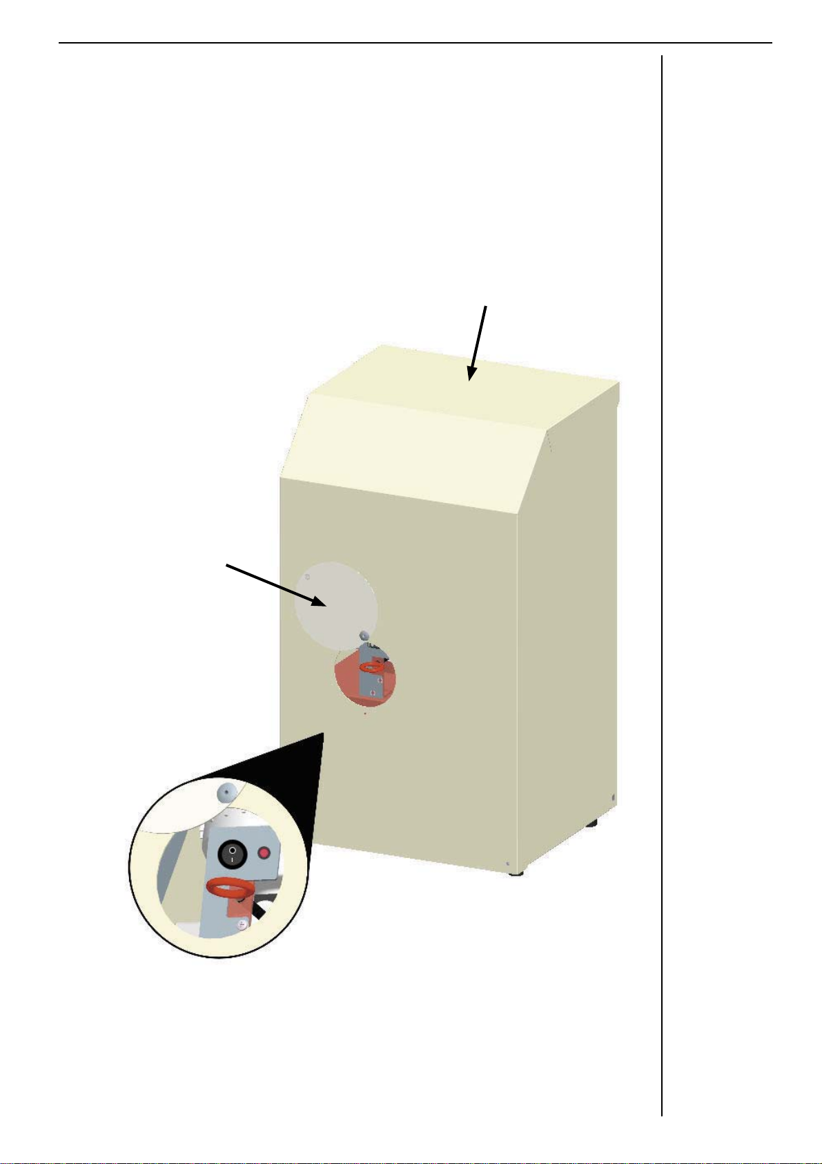
Power Pack Isolate Switch
In order to safely work on the lift and to perform a manual lowering operation,
a Lift Isolate switch has been provided. This switch isolates the 12V power to
the lifts carriage and disables the use of the call stations, re-levelling system
and gates when turned off. The switch contains a red indicator which will only
be illuminated when in the on position.
Detailed
View
of Switch Panel
and Emergency Release Handle
Powerpack
Assembly
Emergency
Access
Panel
6
Melody 2 Hydraulic MK2 Installation Manual - Issue f
Powerpack / Circuit Box and Cable Runs
Ref. ED20102c
Fit the hydraulic powerpack in a suitable location using 2 x 10mm Rawl bolts.
Fit the electrical control box as close to the powerpack as possible. Use the
mounting brackets supplied.
Fit the Earth bonding cables to the base plate and each guide.
Run the hydraulic hose in a suitable conduit from the ram to the powerpack. The
hose elbow goes on to the ram.
DANGER!. DO NOT turn power on from 13Aspur until lift is wired fully, and all
Control Mechanism Switches are adjusted.
Terminate the following cables into the control box and pump as follows. See
wiring diagram in Melody 2Hyd Installation Manual (PG25).
1. 1 x 7 core or 4 core from the upper call station.
2. 1 x 7 core or 4 core from the lower call station.
3. 1 x 7 core from the upper gate lock.
4. 2 x 7 core trailing cables from the RH guide.
5. 1 x 3 core from the mains spur.
6. 1 x 2 core from the pump solenoid.
7. 1 x 3 core from the pump mains up.
Wiring to be carried out by a competent person.
House the wiring in suitable conduit and terminate correctly where entering the
boxes.
NOTES
Earth Bond cable is
fastened to the guides
above cable slot using
a CB003 bolt & CW003
washer on both sides
and to the base place
on central m stud.

Melody 2 Hydraulic MK2 Installation Manual - Issue f
7
NOTES
Installing Melody 2 Hydraulic Lift
Ref. ED20129e 23/08/2011
Specialist tools required
22mm SDS drill bit
Chain splitter
Pin punch
Metal cutting circular saw
Arrival on site
Lifting Height Application
750mm - 950mm Public and Domestic Access
951mm – 2000mm Public and Domestic Access
2001mm – 3000mm. Domestic Access only
Ensure the site is to the correct specification:
Lifting face vertical
Height not exceeding the type of lift ordered
Upper level plinth 1500mm x 1500mm x 200mm deep
Lower landing base level
Ducts , power supply on a dedicated supply and RCD protected as
specified on drawing
Ensure the site is safe to start work and also safe for the public.
Carry out any risk assessments if required.
Speak with end User to ensure they are aware of power pack positions and
call stations.
If the lift is to be sited between walls check the distance between them is at
least 1400mm and the walls are square to the lifting face.
Installation Procedure
1. Unpacking
Unload the lift carefully storing all unpacked parts safely out of harms way
and without any risk of falling.
Melody 2 Hydraulic MK2 Installation Manual - Issue f
8
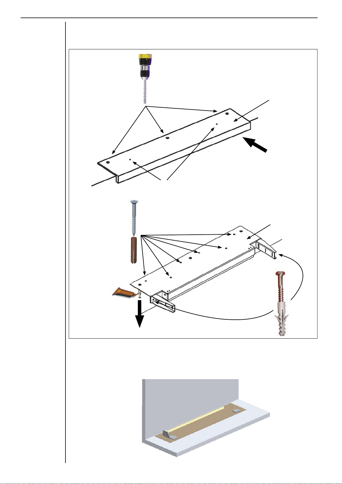
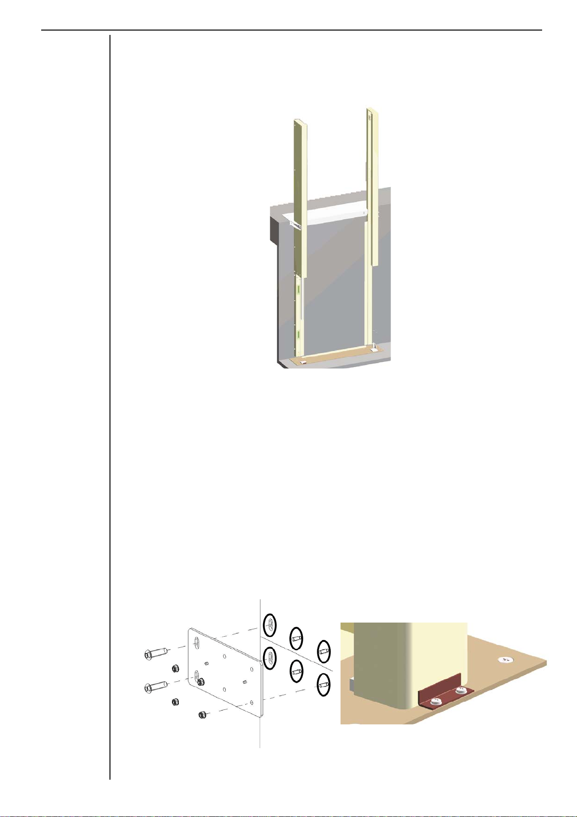
NOTES 2. Upper Level Plinth
Follow the diagram below to fix the upper level plinth.
3. Base Plate (initial)
Supatrol the underside base plate and position it at the lower level. If
necessary pack the base plate so as to make level in both directions and
also level the surrounding area that the lifs car will land on. Do not fix
down yet.
322mm Diameter holes Jig
2.
Drill through two small fixing
holes and use screws and
plugs to secure jig in position
1.
Ensure the jig is pushed
hard against the lifting face
4.
Inject chemical fixing
into each spigot hole
then lower the plinth
into position
5.
x6 into plinth top
CF154 (screw)
CF120 (plug)
Upper Level
Plinth Fabrication
6.
x2 into lifting face
CF207 & CW066
CF206 (plug)

Melody 2 Hydraulic MK2 Installation Manual - Issue f
9
NOTES
4. Cutting of the Main Uprights and Lower Guides
Use a jigsaw or metal cutting saw to cut uprights and guides. Ensure burs are
removed and treat cuts before fitting as follows: Seal all exposed edges using
a touch-up can. Seal further with Supatrol once the paint has dried.
RH Main Upright: (60 x 60 Box Section)
Cut the upright using the following formula:
Measure from the baseplate top surface to the upper
level plinth top surface (Distance X).
For a 2m lift:
2000 – Distance X = calculated length (amount to cut
off).
For a 3m lift:
3000 – Distance X = calculated length (amount to cut
off).
Now cut the calculated length off the bottom of the
lower guides and main uprights OR In the case of a
3m lift, cut the calculated amount off the bottom of the
lower extension box section.
LH Main Upright: (60 x 60 Box Section)
Cut the calculated length PLUS 260mm off the LH Main Upright. This will
place the cut at 300mm above the base plate, which is the point where the
lower gate enable switch must roll off to enable the car gate.
Continued Over:

Melody 2 Hydraulic MK2 Installation Manual - Issue f
Guides
Cut the calculated length off the lower LH and RH Guides.
Take the off- cut from the lower left hand guide and copy the outline of
the ram cut-out onto to remaining guide. Either use a jigsaw or metal
cutting saw to create the guide cut-out. Seal all exposed edges using a
touch-up can. Seal further with Supatrol once the paint has dried.
10
NOTES
5. Upper Left Hand Guide Box Section
Attach the upper left hand guide and top cap to the left hand upright. If the
lift is a 3m model, an upper extension box section needs to be fixed onto
the top end of each upright. This is secured with M8 bolts inside and M8
countersunk bolts from above. Use M6 countersunk bolts in the sides.
A new square shaped washer is needed to locate the guide fixing bolt
centrally in the slot in the guide bracket when the guides are being attached.
Place washer into the bracket with the hole and slot aligned, the washer
can go in either way up with the flat side against the inside face of the guide
bracket.
f guide adjustment is required move this washer and replace with the M10
washer provided.
Melody 2 Hydraulic MK2 Installation Manual - Issue f
11
Apply chemical fixing to areas
highlighted by black rings
Fish plate diagram Guide Fixing Bracket
Offer the left hand upper guide/upright assembly to the upper level plinth and
secure using an M12x110mm bolt. Once fitted, ensure a 40mm gap exists
between the base plate and the bottom of the upright. This is to allow the
trailing cables to exit the upright.
6. Upper Right Hand Guide
Attach the right hand upper guide/upright assembly to the upper level
plinth in the same way.
7. Lower Right Hand Guide
Fix the guide in place using M10 screws into the uprights. Fit the fish plate
by appling chemical fixing to the area around the fixing holes in the guides
before screwing the fish plate in to place. Fit the guide joining tab. Ensure
the bottom end of the guide is positioned correctly and secure using a
small guide fixing bracket.

Melody 2 Hydraulic MK2 Installation Manual - Issue f
12
8. Ram
Carry the ram from the van (2 people) and locate between the pins
on the left side of the base plate. Ensure the head of the ram and the
bleed points are facing the correct way.
9. Lower Left Hand Guide
Fix the guide in place using M10 screws into the uprights. Fit the fish
plate by applying chemical fixing to the area around the fixing holes
in the guides before screwing the fish plate in to place. Fit the guide
joining tab. Ensure the bottom end of the guide is positioned correctly
and secure using a small guide fixing bracket.
Fit the ram catch tank.

Melody 2 Hydraulic MK2 Installation Manual - Issue f
13
NOTES
Important! Ensure both guides are in good contact with the base plate and
that the baseplate is level in both directions.
Ensure the right hand guide is perfectly vertical in both directions by
moving the baseplate accordingly. Secure the right side of the baseplate
with two stainless steel screws and rawl plugs. Fit the remaining baseplate
screws.
Tighten all guide mounting screws and ensure structure is secure.
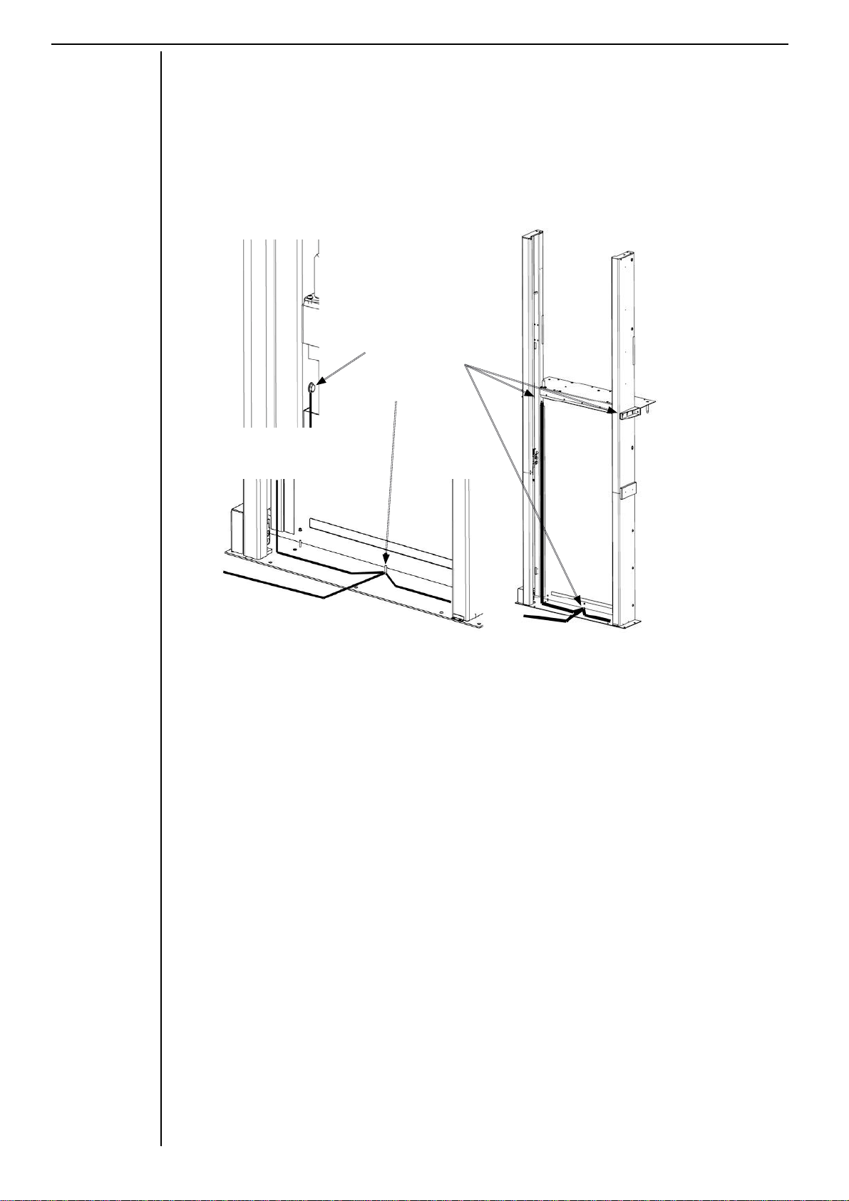
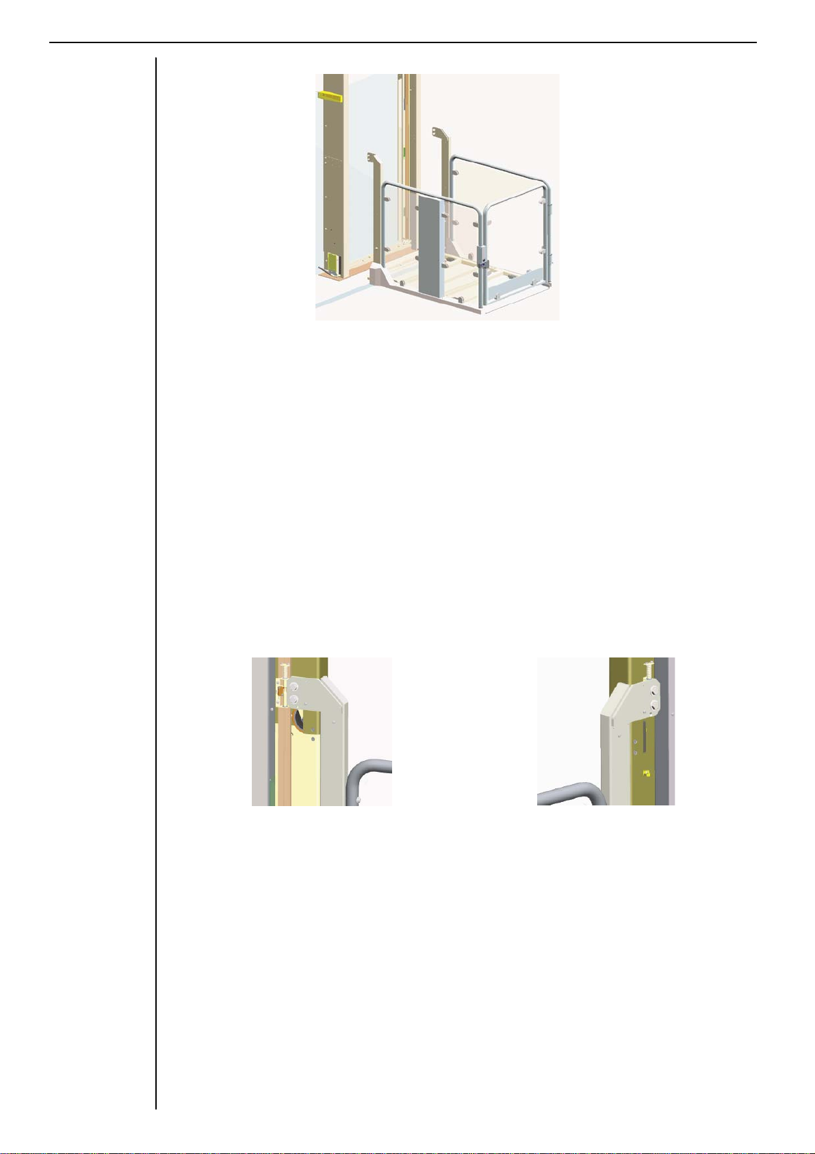
10.Upper Level Gate
Fit the lower hinge boss as detailed below.
Lubricate the pivot boss before the gate is fitted over it.
Fit the upper level gate, ensuring the glass is on the carriage side, flush
with the lifting face.
Secure top hinge bracket securely and align gate beak to gate lock.
If required, the gate can be re-handed on site by following these steps.
CRITICAL: THE FLUSH SIDE OF THE GATE MUST BE FACING THE
PLATFORM / LIFTING FACE
Lay the upper level gate down
on cardboard or similar protection
to ensure that it does not get
damaged and consider which side
becomes the hinged side and ensuring
the glass is on the carriage side.
Fit the lower hinge boss to the upper
level plinth.
Push the black nylon insert into
the top of the gate frame and then
fit the top gate bracket.
Fit the black 25mm cap in the
opposite end of the frame.

Melody 2 Hydraulic MK2 Installation Manual - Issue f
14
NOTES Remove the gate beak bracket
assembly and move the correct
set of inserts to ensure the bracket
aligns with the gate.
Drop the gate over the gate pivoit pin
(Lubricating the pin first).
Ensure the glass is on the carriage side.
Fit the 2 black bushes in clips into
the unused inserts.
11.Upper Call Station
he upper call station is pre-fitted to the main upright.
n additional call station (free standing post, flush or surface mounted)
can
be fitted if specified.
12. Lower Call Station
Fit the lower call station in a suitable position 1000mm off the floor and run
the cable back to the control box position.
13. Energy Chain Roller Assembly
Fit the energy chain roller guide assembly into the right hand guide with
the energy chain attached and pass the two trailing cables behind the
lower gate enable switch. Locate the end of the energy chain channel into
the socket on the right hand side.
Remove the 2 x M12 bolts and keep safe.
Melody 2 Hydraulic MK2 Installation Manual - Issue f
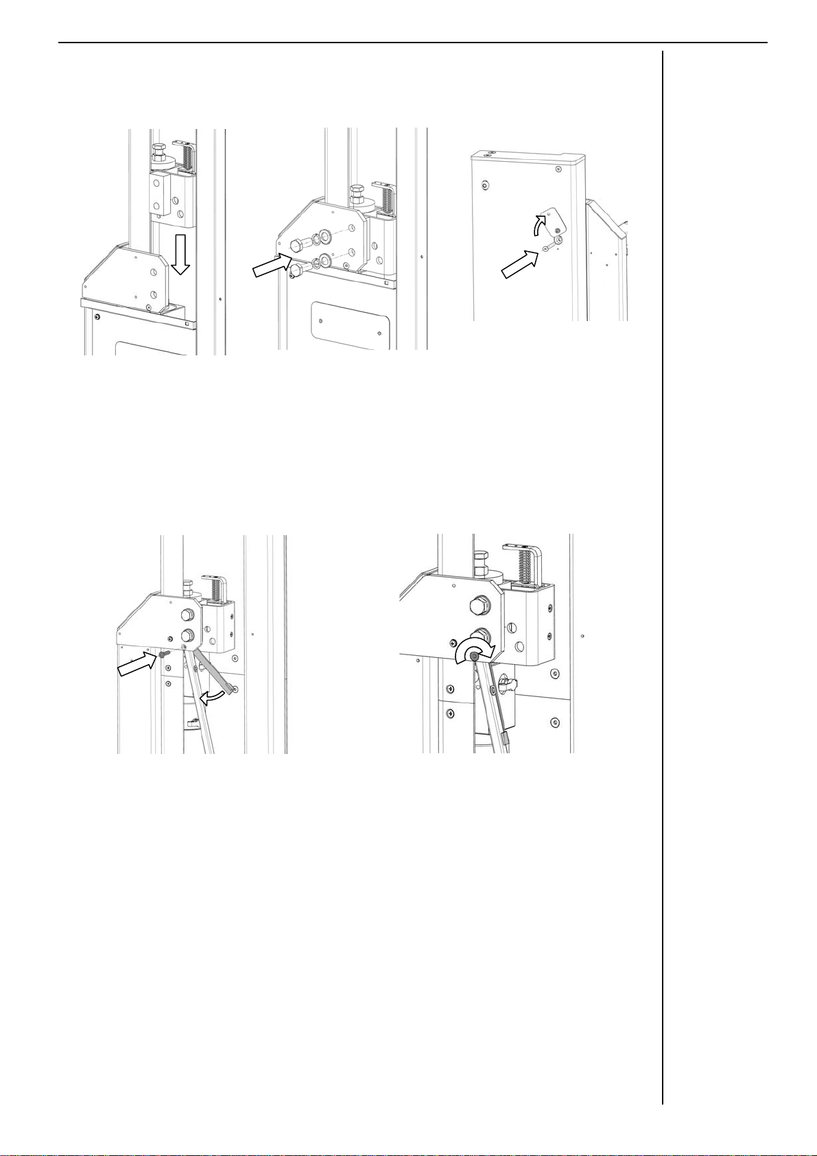
The method for fixing the new ‘ram-to-carriage bracket’ into position is very similar to the
previous method;
The method by which the anti-creep support bracket now fixes to the carriage up-right has
also slightly altered;
Adjustments to the safe switch can be made by using the access holes to the rear of the new
ram bracket.
Fit the bracket into the
guide then slide downwards
onto the top of the ram.
Fix into position using the
usual M12 x 30
bolts/washers
(2 x ‘CB263/CW187/CW018’).
Take the lift to its upmost
position and undo one of
the screws in the upper
gate blanking plate. Turning
this out of the way, secure
the ram head into position
using a M6 x 60 CSK bolt
(CB097, as pictured).
After fitting the ‘ram to carriage
bracket’ as above, place the
anti-creep support bracket
behind the carriage up-right and
fix into position using the clamp
plate and M6 x 30 CSK screw
(LT04917 and CB066).
a)
Screw into position whilst
holding the clamp plate. As it
begins to tighten, release the
clamp plate and tighten fully.
The clamp plate is shaped so
that it should be hard up against
the anti-creep support bracket.
b)
c)
b)
a)
15
NOTES
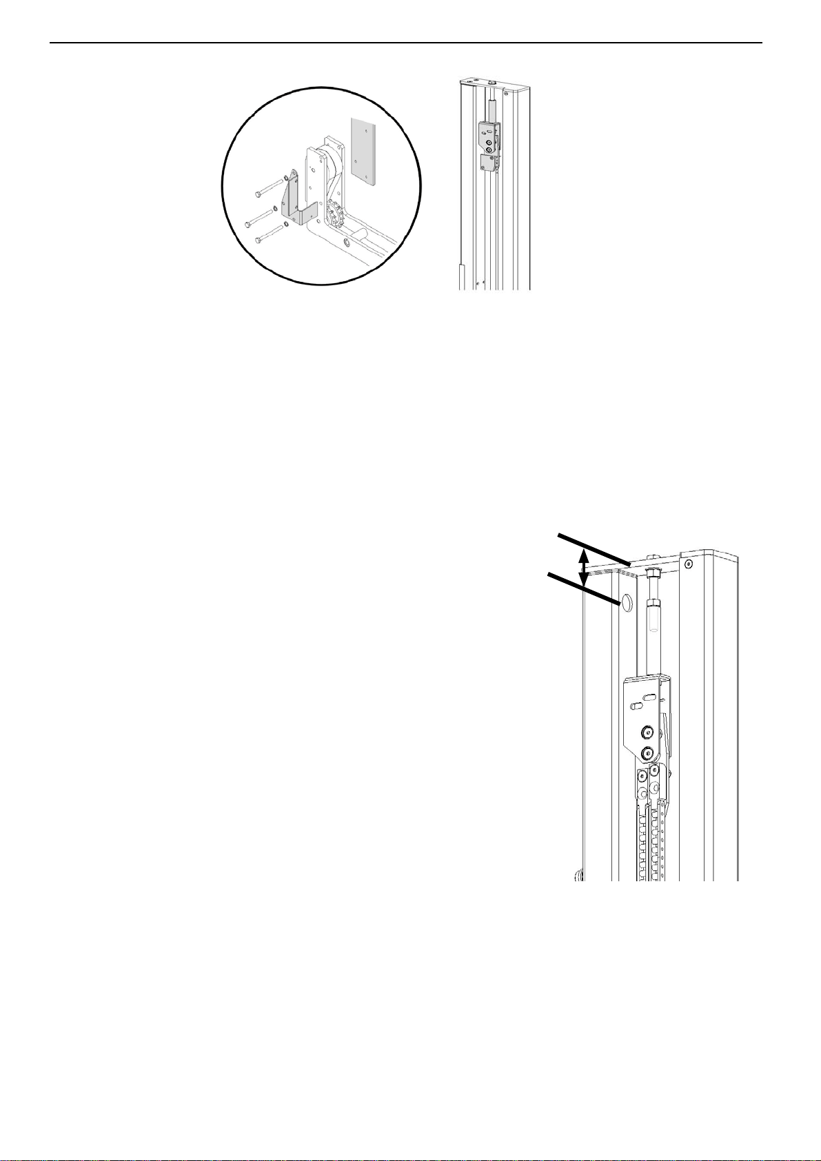
14. Ram Head Assembly
15. Chain Drive Assembly
Fasten the Anti-Creep Bracket Assembly (LT04427) to the chain drive
assembly using the M6 x 70 Hex. Bolts (CB179) and M6 Shake-proof
Washers (CW017) provided with the Anti-Creep Assembly.
Be sure to fasten through the left hand inner
cover mounting bracket (LT04553)
Melody 2 Hydraulic MK2 Installation Manual - Issue f
16
Lay out the chain drive assembly ensuring that no dirt or grit gets in the links, and attach
the Anti Creep unit as detailed above. The chains now need to be cut to length.
On the chain equaliser assembly, remove the chain from the swivelling chain brackets -
see B.
Attatch the chain equaliser assembly to the top right hand guide as normal, ensuring the
minimum engagement of the top adjustment bolt. - see A.
Fit the chain assembly, feeding it into the right hand guide. Sit this assembly on a suitable
packer on the baseplate (around 250mm high). Fit four M8 x 30mm countersunk allen
bolts to secure the chain brackets to the baseplate.
IMPORTANT:
The top bolt (M12x100 set screw, 12.9 grade) must
be engaged by a minimum of 30mm, when the lift is in
operation
This means that a absolute maximum distance of 64mm is
allowed between the underside of the top plate and the top
of the tapped boss of the chain hanger. (See diagram)
16. Carriage Assembly
The following diagrams and notes describe in detail assembly of the flat-packed carriage.
Follow them carefully and ensure all bolts and screws are correctly tightened.
Fit the side trim covers with glass clamps pre-attached.
Remove the bottom glass clamp on the gate hinge side handrail and slide handrail
through gate hinge tubes. Replace glass clamp afterwards. Then fix whole assembly to
carriage.
Fit the handrail assemblies using the fixings provided.
Once the Platform is attached to the chain
drive assembly, pull each chain through the
appropriate chain equaliser attachment
block (top right hand guide) to establish
where each chain needs to be cut (see B).
Cut the chains and re-attach to the swivelling
blocks.
Adjust the top bolt to level the platform as normal
MAX 64mm
B
A
Melody 2 Hydraulic MK2 Installation Manual - Issue f
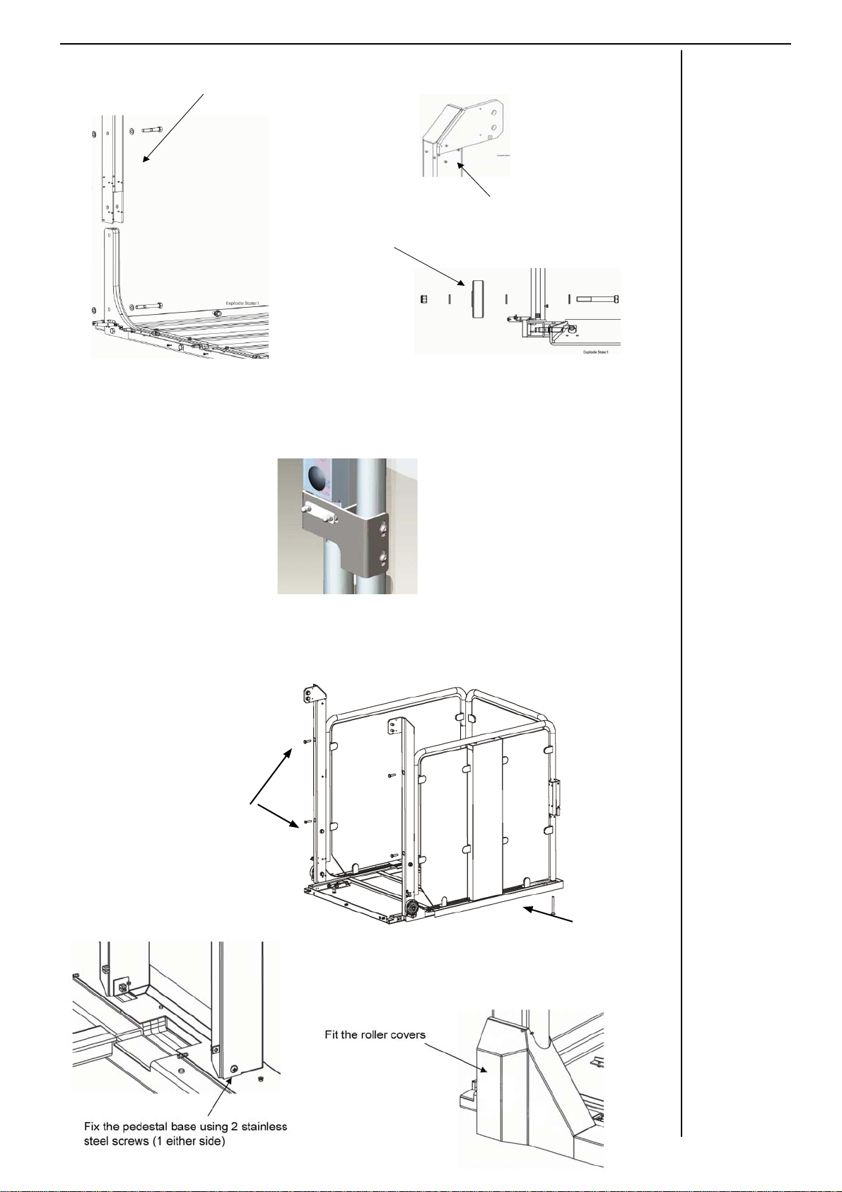
1
clowns feet
Fix the backpillar and roller
Orientation of the roller
(thick side of hub faces
outwards)
Top plate of
backpillar on
inside of carriage
17
NOTES
2 x CB303
2 x CZ107 Each side
}
2 x CB243
Ensure very
tight!
NOTE: Box spanner
supplied in fixing kit
The beak bracket on the carriage is now a floating beak
There is no need to adjust the lock beak when the gate is fitted.
Attach the handrails and gate as standard and the self adjusting
beak will slide to the correct position when closing the gate.
Melody 2 Hydraulic MK2 Installation Manual - Issue f
18
17. Attaching the Carriage to the Chain Drive Assembly
Remove the 3 x M12 bolts from the front of the chain assembly and keep
safe.
Position the carriage so its base butts up to the bottom of the chain drive
assembly. Loosely fit the 3 x M12 bolts with washers through the car into
the chain drive assembly.
Fit 2 x M12 bolts through the right hand carriage backpillar into the roller
assembly in the right hand guide.
Fit the 2 x M12 bolts through the left hand carriage backpillar into the ram
head assembly.
Tighten all 7 M12 bolts fully now.
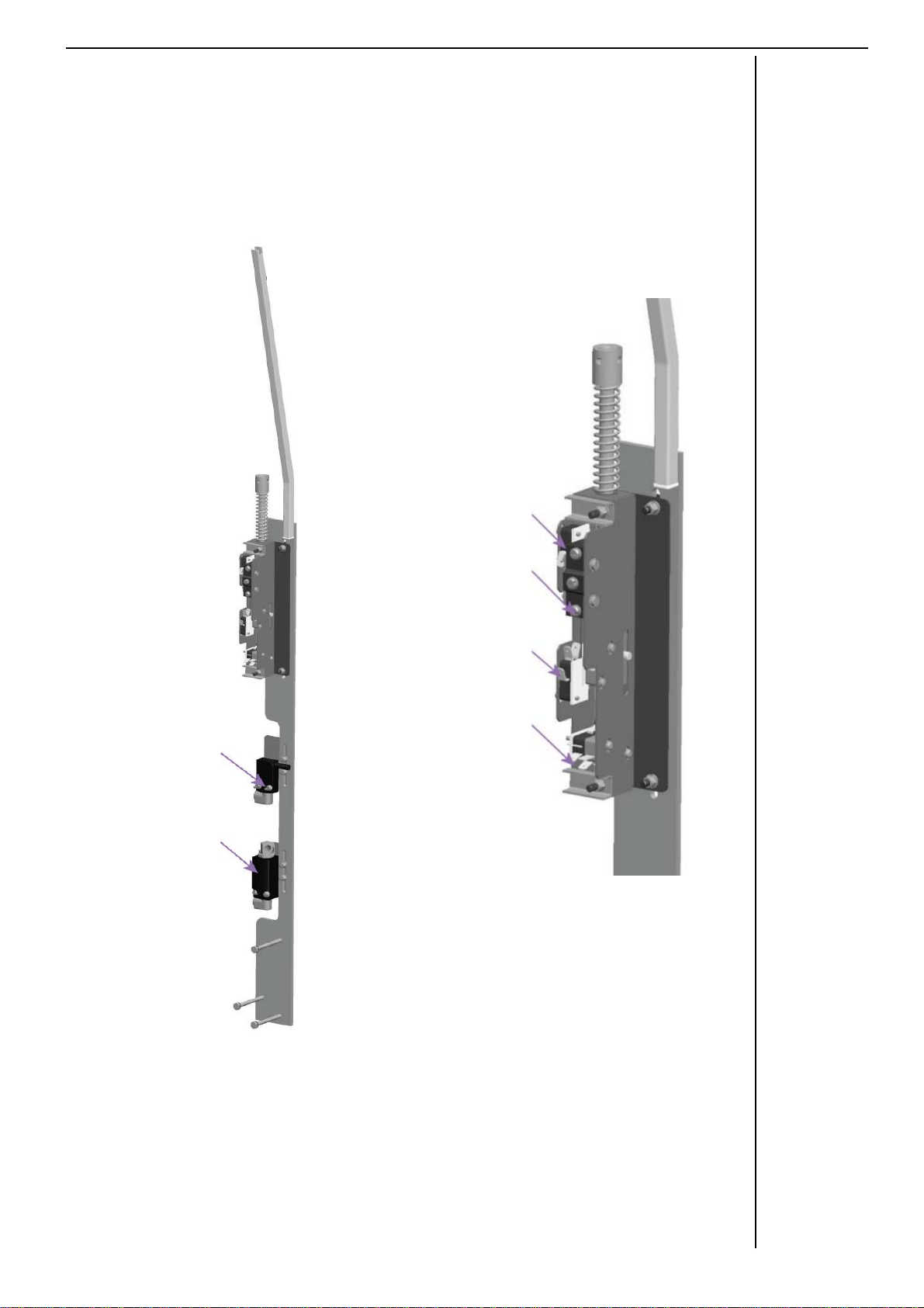
18. Limit Switch Control Mechanism Assembly and Strengthening Brace
The Control Mechanism consists of a number of switches that are individually
adjustable to ensure that the lifts stops at the correct level, the gates only open
when the lift arrives at the associated level, and that the lift will re-level at the
upper level if the hydraulic fluid in the ram were to expand or contract.
Melody 2 Hydraulic MK2 Installation Manual - Issue f
19
NOTES
Complete Control
Mechanism
Assembly
7) Lower Door
Enable and
Underpan Safe
Edge Override
Switch
6) Zone and
Upper Gate
Enable Switch
Control
Mechanism
Switch
Assembly
Control
Mechanism
Switch Assembly
Plunger
1) Creep Switch
2) Latch Switch
3) Top Limit
Switch
4) Dump Switch
5) Final
Limit
Switches
Switch Functions
1 Re-levels in the UP direction
2 Cancels the Creep/Dump Signals
3 Stop Lift if Creep System Disabled
4 Re-levels in the Down direction
5 Blows the Main 5A Fuse to stop lift travel
6 Enables the Levelling system and Upper
Level Gate
7 Enables Lower Level Gate and ram
resynchronisation timer.
The below diagrams show the location of each switch within the control
mechanism

Melody 2 Hydraulic MK2 Installation Manual - Issue f
In accordance with step 26. “Completion
Tasks” of the installation manual, adjust
the Anti Creep unit and the Gate
Activation Switches into their optimal
position using locators on the left hand
gate post.
The Anti Creep unit is pre set; adjust its
position so that the plunger just makes
contact with the anti creep lug on the left
hand gate post when the lift carriage is in
the upper level position and the platform is
flush with the upper landing.
Adjust the Gate Activation Switches
to achieve full engagement at the upper
and lower levels. The Lower switch will
drop off the end of the gate post (as
modified on site) to activate. The upper
will activate in the slot provided
Secure the anti-creep support bracket in place using the M6 x 30 CSK Screw
(CB066) + M6 Washer (CW005) & M6 Nyloc (CN002)
20
NOTES
Secure top of
brace with single
countersunk
M6 screw and
combie nut
Table of contents
Other TERRY Lifting System manuals


Popular Lifting System manuals by other brands

SAMES KREMLIN
SAMES KREMLIN 102 415 0001 manual

PFlow Industries
PFlow Industries Cartveyor CV Series owner's manual

morse
morse 400AM-60 Operator's manual

EAE
EAE EE-6214EKZ Installation, operation, and parts manual

Basta Boatlifts
Basta Boatlifts Over-Center 2k40 manual

ABS
ABS Sanimat 1501S Installation and operating instructions


