DEALER INFORMATION
Name:
Contact:
Telephone:
2.3 MANUFACTURER’S NOTE
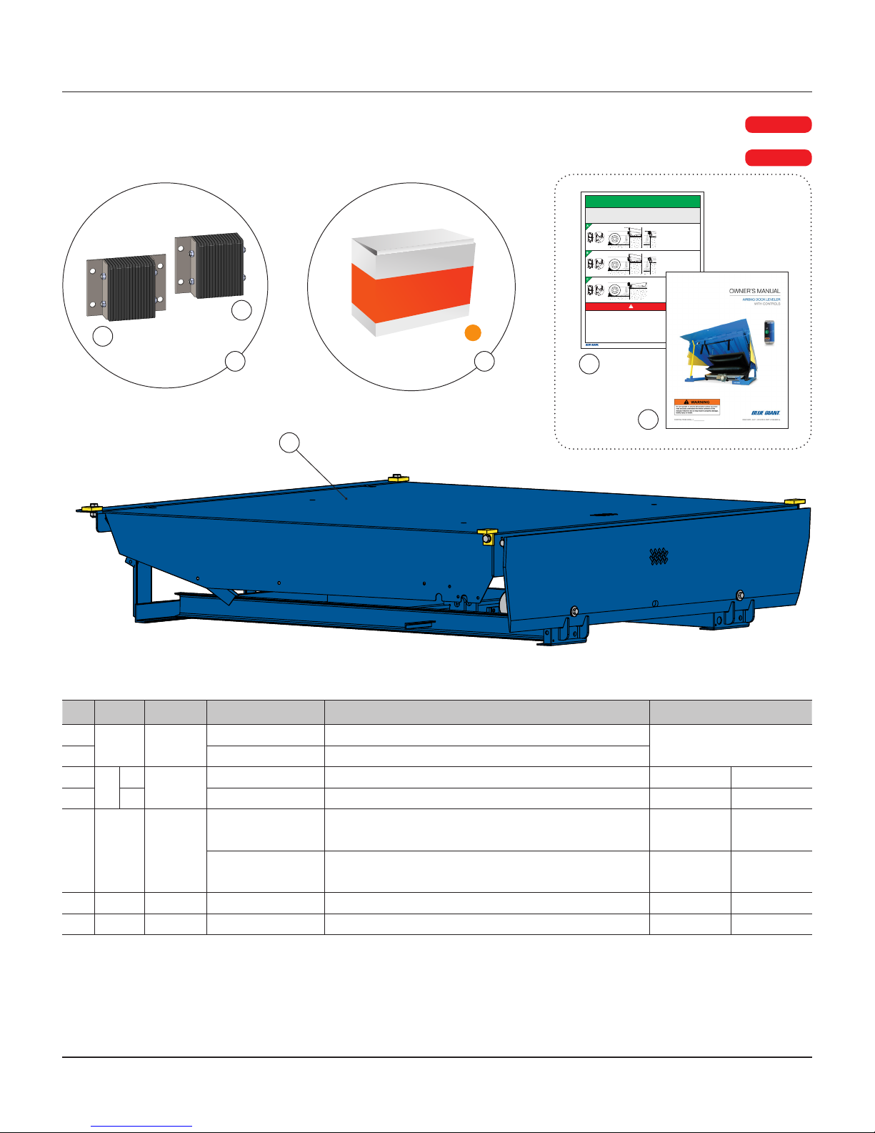
The dock equipment has been carefully inspected and tested at
the manufacturer’s plant prior to shipment, but should be checked
upon receipt for transport damage. Any observed transport
damage is to be listed on the signed copy of the freight document.
Notify the freight forwarder of any damage WITHIN 48 HOURS.
2.2 EXCLUSION OF LIABILITY
The manufacturer assumes no liability for damage or injury to
persons or property which occur as a result of defects or faults in
or incorrect use of the Loading Dock Equipment. The manufacturer
also assumes no liability for lost profits, operating downtimes, or
similar indirect losses incurred by the purchaser. Injury to third
parties, irrespective of its nature, is not subject to compensation.
The manufacturer reserves the right to make changes at any time
to the modules, components, and accessories, concurrent with
its continuing product improvements and development program.
Specifications, operating instructions, and illustrations included in
this manual are subject to change without notice. Please contact
manufacturer for the latest information.
BLUE GIANT SERIES DOCK LEVELER—INSTALLATION & TECHNICAL MANUAL
5AUGUST 31, 2018 REV.1 (PART # 038-1073EI)
2.0 INTRODUCTION
The following is a quick reference to important procedures that
must be followed while installing the Loading Dock Equipment. It is
not intended to cover, or suggest that it does cover, all procedures
necessary to ensure safe installation and operation. All person-
nel who install and / or use this dock equipment should be aware
of and abide by all workplace safety regulations applicable to the
installation and operation of the Loading Dock. These laws and
regulations include but are not limited to:
• The Occupational Safety and Health Act
• Canada Occupational Health and Safety Regulations
• Occupational Safety and Health Acts for Individual States
(USA)
For additional information on these regulations as well as industry
standards that may apply to this product, please contact:
American National Standards Institute (ANSI)
1899 L Street, Washington, DC 20036
Telephone: 1.202.293.8020
www.ansi.org
Also a member of:
Loading Dock Equipment Manufacturers
A Division of Material Handling Industry
8720 Red Oak Blvd, Suite 201, Charlotte, NC, 28217-3992
Telephone: 704.676.1190
www.mhi.org/lodem
2.1 WARRANTY INFORMATION
Thank you for purchasing Blue Giant products. We appreciate
your business, and are confident that our product will serve
you for many years to come. In the event that you experience a
problem with our product, our Warranty Center is here to support
the Blue Giant Product(s) that you have purchased.
To validate warranty on recently purchased equipment,
please complete and submit your information with our
online Warranty Registration at www.bluegiant.com.
For more information about Blue Giant Warranty Support, please
contact your local Blue Giant Equipment dealer, representative or
authorized partner near you. You may also visit www.bluegiant.com
or phone 1.905.457.3900.
NOTE: Failure to validate warranty at the time of receipt can
seriously affect the outcome of any claim.
NOTE: Improper installation of equipment may void any
applicable warranties.
2.4 INSTALLER’S GUIDELINES
Please read all instructions carefully before installing this
Blue Giant dock product. It is the installer’s responsibility to
comply with the following:
• The installation of Blue Giant dock products should comply with
all applicable local or national building codes and regulations,
including any that may supersede this manual.
• Site surveys and other applicable install-related documentation
must be properly and accurately completed prior to installation.
Failure to comply with this requirement may result in an
improper install and possible voiding of the warranty.
• Only Blue Giant-supplied or approved parts must be used. Any
unauthorized parts substitution may void the warranty.
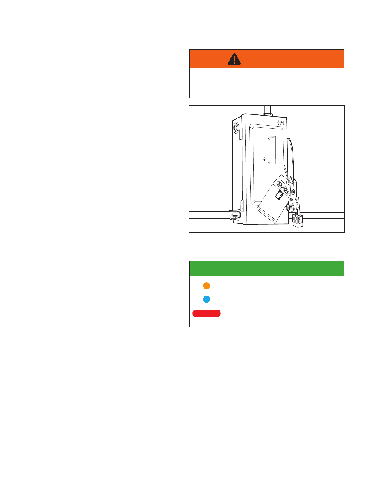
Always lockout and tagout any power source before performing
any electrical work, in accordance with OSHA regulations and
approved electrical codes. The installer is responsible for reading,
understanding, and complying with all personal protective
equipment (PPE) policies in effect.