Sicon EVMS Series User manual

1
Electric Vehicle Charging Station
EVMS-150
2021 V1.0
USER MANUAL

2
Content
PART 1 Safety Instruction ..................................................................................................................3
1.1 General Instruction .............................................................................................................3
PART 2 EVMS-150 Charger Installation............................................................................................5
2.1 transport .............................................................................................................................5
2.2 Charger Receiving Inspection...........................................................................................5
2.3 Charger Storage...................................................................................................................6
2.4 Installation environment.....................................................................................................6
2.5 Unboxing .............................................................................................................................7
2.6 Position................................................................................................................................8
PART 3 Introduction and installation of charge ............................................................................10
3.1 Product Overview..............................................................................................................10
3.2 Feature ..............................................................................................................................10
3.3 Outline Dimension ............................................................................................................11
3.4 Appearance .......................................................................................................................12
3.5 Charger dust screen and air inlet and outlet.....................................................................14
3.6 Charger diagram................................................................................................................17
3.7 Input Connection Terminals ..............................................................................................18
3.8 Install and remove the main power module.....................................................................19
3.9 After the initial setup boot................................................................................................20
3.10 Charging status indicator.................................................................................................20
3.11 Emergency stop button...................................................................................................20
3.12 Charger connector bin.....................................................................................................21
3.13 RFID Card reader .............................................................................................................21
3.14 Charging strategy ............................................................................................................21
3.15 Charger parameters. .......................................................................................................22
PART 4 Product Overview ..............................................................................................................23
4.1 Module Introduction .........................................................................................................23
4.2 Appearance .......................................................................................................................23
4.3 Feature ..............................................................................................................................25
4.4 Module diagram................................................................................................................25
4.5 Specification ......................................................................................................................26
PART 6 Charging Operation............................................................................................................27
6.1Charging Flow Chart...........................................................................................................27
6.2 Charging process ...............................................................................................................28
PART 7 Enter the administrator interface .....................................................................................29
7.1 How to enter the administrator interface.........................................................................29
7.2 Each unit described ...........................................................................................................30
PART 8 Troubleshooting.................................................................................................................31
3
PART 1 Safety Instruction
1.1 General Instruction
Operating at AC mains high voltage, the charger is composed of high current/voltage withstanding
components. Proper installation of the charger to be grounded to defense electric shock and
foreign objects. Installation service should be performed by qualified technician or authorized
service partner of the manufacturer.
WARNING!
Operations inside the charger should be performed by qualified
technician or authorized service partner of the manufacturer.
1.1.1Symbols introduction
WARNING!
Warning
Refer to the manual for more information.
Danger
There is risk of electric shock, the charger has high voltage.
NOTE!
Note
Read this information to avoid damage to the charger.
1.1.2 Grounding symbol
Protective grounding wire
Grounding terminals must be connected before making other
connections to the charger.
1.1.3 Safety notes
1) Please carefully follow the safety instructions to keep the electric car out of danger;
2) Before charging, check the charger touch screen and indicator light. If there’s fault, the fault
must be solved before using the charger to charge.
3)Before the charger starts charging, make sure that the Electric car is in power off state;
4) Completely follow the text prompts to conduct charging process.

4
5) It is prohibited to unplug the charging connector during charging process to prevent Any
kind of unwanted accident and ensure safety;
6) The entire charging process is completely automatic, EVMS-150 will shut down by itself
while it finishes charging the car. The charging process don’t need any human intervention but we
recommend regular inspection to check if there’s any abnormal situation,
7) When not in use, try to avoid direct exposure of the tip of Charging connector, and plug it
back into the socket to prevent damage. Check the charging cable or charging tip if the shell is
damaged, exposed cables and other problems, please stop using until fixing it t;
5
PART 2 EVMS-150 Charger Installation
2.1 transport
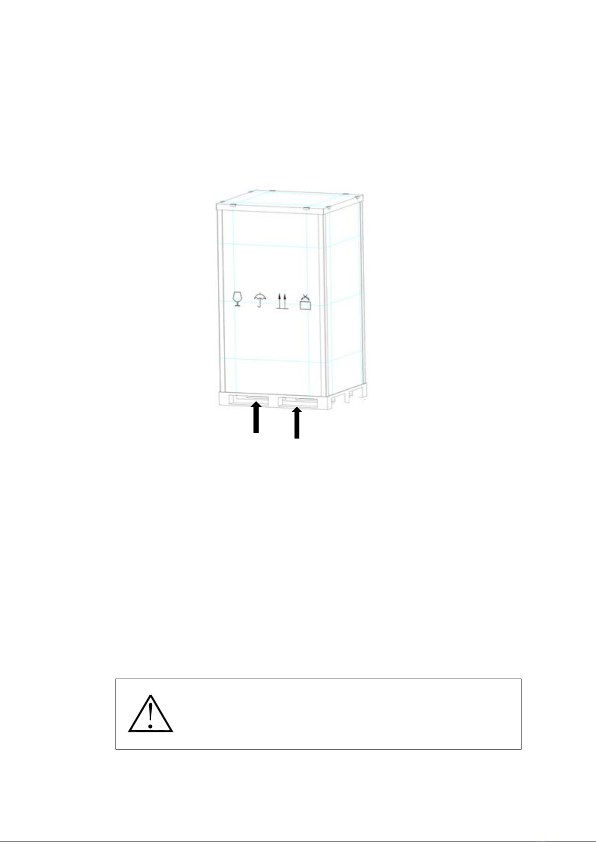
Note: The center of gravity of the equipment is not in the center. When using a forklift to
unload and transport, please fork in the direction as shown in the figure to prevent the
equipment from tipping over.
sketch map
Transport, road transport choice, should choose a better road traffic, to prevent
excessive turbulence can also choose rail transport and water transport.
2.2 Charger Receiving Inspection
When receiving the charger, please carefully check the box and the charger whether there are
any signs of physical damage. The logo on the box should be complete. If there is a rupture or
suspected rupture, please inform:
* Carrier
* Manufacturer
NOTE!
Visible Transport Damage must inform the carrier immediately upon
receipt of the goods!
Other transport damage must also be declared immediately and the

6
carrier must be notified within seven days of receiving the equipment.
The packaging material should be kept for later inspection.
2.3 Charger Storage
If the charger is not to be installed immediately it must be stored in stable position, and in a certain
temperature and humidity environment, the environmental conditions are as follows:
Temperature : -25°C to 60°C
Relative humidity: ≤95%, non-condensing
The recommended storage temperature is between: 10°C to 30°C.
2.4 Installation environment
To ensure the safe and healthy use of the charger, the location should be appropriate. Not only to
maintain a clean working environment, avoiding moisture, flammable gases, flammable liquids or
corrosive substances; users can place them at designated locations by means of manpower or
equipment, but be careful to maintain the spacing around the charger, to facilitate air circulation
and heat dissipation.
The following points should be noted:
A minimum of one meter of space must be left in front of and behind the machine to ensure
adequate space for operation and maintenance.
The input cable for the AC enters from the bottom of the charger.
Input and output wiring check
To ensure the safety of personnel during the installation of the charger, it is important to ensure
that all connections are made in the following conditions:
●Keep EVMS-150 installation area clean and dust free
● All power cables are Proper length and diameter
●Startup and operational checks are performed by authorized service personnel.
●Confirm the input and output voltage and frequency of the charger
●Ground connection in accordance with IEC standards or local regulations.
7
Installation environment
●Sufficient ventilation distance should be maintained on all sides of the charger case
●Away from heat and corrosive substances, avoid direct sunlight
●Maintaining normal operating temperature and altitude; Working temperature: -20 ℃~ 60 ℃
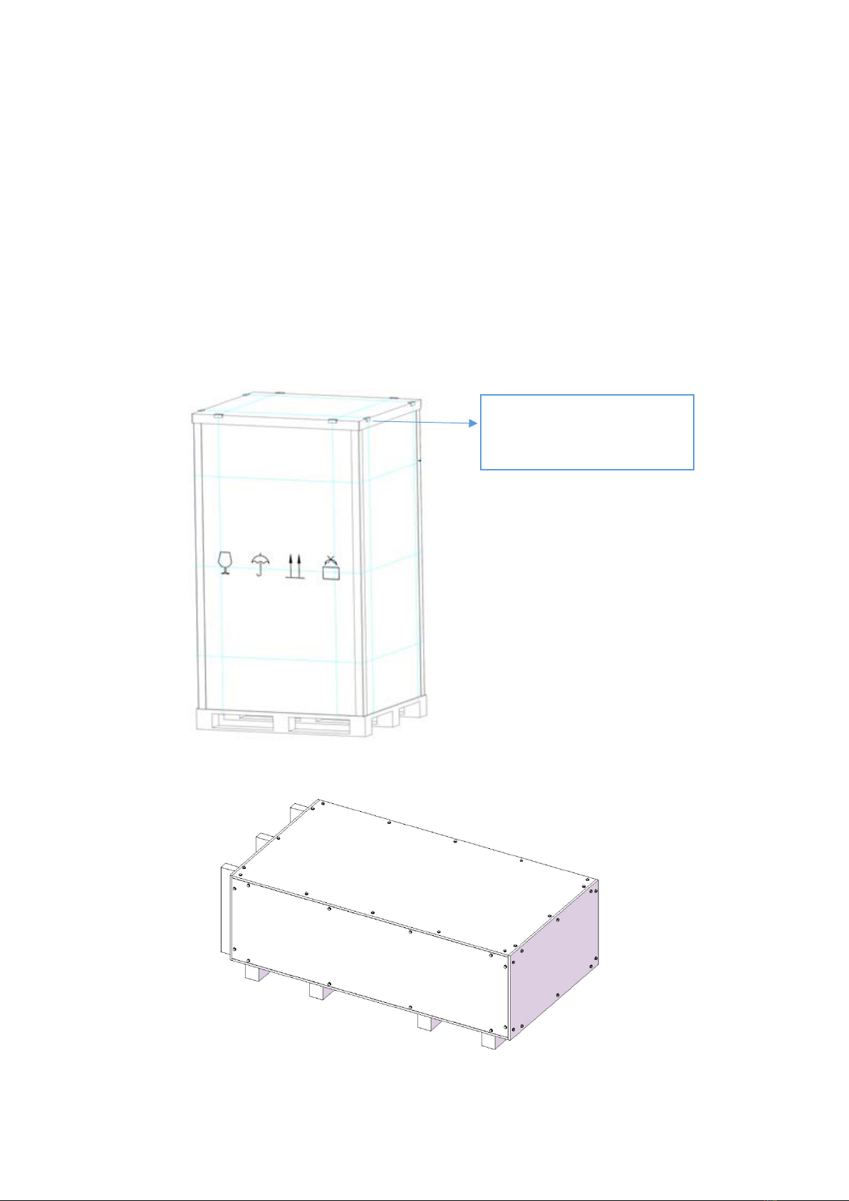
2.5 Unboxing
Vertical steel edge wooden packaging
Horizontal detachable packaging
Disassembly and assembly are carried out in the horizontal state:
Use a flat-blade
screwdriver to open it to
remove the wooden box

8
Use the open spanner SJGJ-17-19 to disassemble and assemble the bolts and washers in
the blue frame line as shown in the figure, each with 40 pcs.
Save the bolt, washer, and the honeycomb inner corner removed, according to the
position of the mounting place when unpacking the package again.
2.6 Position
In order to ensure smooth and reliable charger, the charger must be vertical basic construction
charger mounted on cement concrete cement based on custom and mounted above the base
level of the ground is not less than 220mm,.
Drilling template according to claim 6 Drill hole depth of 12mm in diameter 100mm in a cement
base, and then through the wall portion of the expansion bolt is inserted in a hole drilled;
Charging the cement foundation piles and reliable ground connection, the ground resistance
must ≤4Ω.
Before installing the charger, it should be checked as follows: the
device is damaged, if damaged, the shipper immediately; product
label check, confirm the correctness of the device. The equipment
label is affixed to the equipment, and the model, capacity and main
parameters are indicated on the label.

9
Front
Remove the anti-vibration components at the bottom of the cabinet, and then use a crane
(recommended) or a forklift to move the cabinet to the installation location on the concrete
foundation.
NOTE!
1. The lifting equipment used to carry the charger must have sufficient lifting
capacity.
2. When removing the loaded pallet, ensure that there is sufficient manpower
and lifting equipment.
3. The charger has a high center of gravity, so be careful to tip over.
Base anchoring hole diagram

10
PART 3 Introduction and installation of charge
3.1 Product Overview
EVMS series Electric Vehicle charger station is an intelligent integrated DC charging station system
promoted meet market demands. It adopts modular concept and cutting-edge electronic circuit
technology, integrating power conversion, charge control, management, query, display and
background communication in one cabinet. By communication with the BMS of electric vehicles,
to achieve intelligent control of the entire charging process. It is composed of Human-machine
Interaction Unit, Control Unit, Charging Module unit, Measurement Unit and Protection Unit. The
design conforms to EN61851, EN62196, DIN70121, CHAdeMO1.2 and other standards.
3.2 Feature
The charger supports CCS2 connectors could be used simutaneously.
Built-in power meter with charging power metering function.
Configured with DPM1000/30 charging modules.
Support RFID Card charging(Mobile app optional) , support reservation function.
widescreen TFT touch screen with good human-machine interface, which can display QR code,
status information, metering information, alarm, charging records, etc.
LED indicators of power, charging status and fault.
Self-identifying electric vehicle BMS protocol function, mufti-models compatible charging;
Emergency stop button can cut off the charger output in urgent situations.
protection, AC input over voltage protection, AC input under voltage protection, short circuit
retraction protection, DC output over voltage protection, DC output under voltage protection,
battery anti-reverse protection, current anti-reverse and other protection functions;
Charging process protection function, when it occurs BMS communication failure,
disconnection, battery temperature, voltage exceeds the allowable limit, etc. During charging
process, the charge will immediately stop charging;
11
It has function of communicating with the monitoring system of the station, and can upload the
charging information through Ethernet or 3G, 4G wireless network to realize remote monitoring.
Built-in DSP in the charging module realizes intelligent management and digital control functions;
Built-in active power factor correction module in the charging module, input THDi ≤ 3%; power
factor 0.99.
The charging module adopts ZVZCS and LLC resonant soft switching technology, the efficiency up
to 95%.
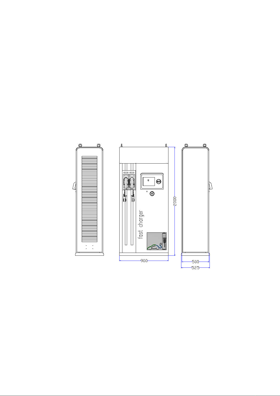
3.3 Outline Dimension
12
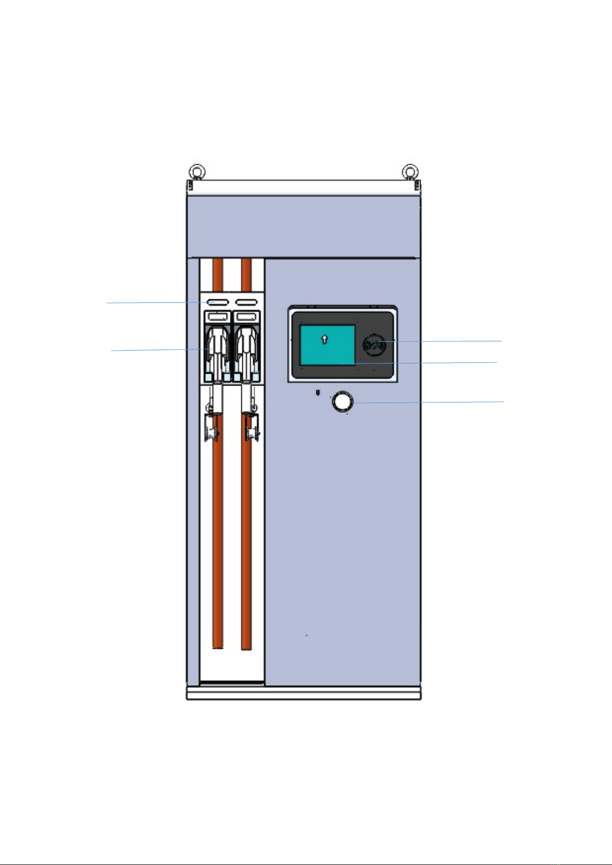
3.4 Appearance
Front View
1
23
5
4

13
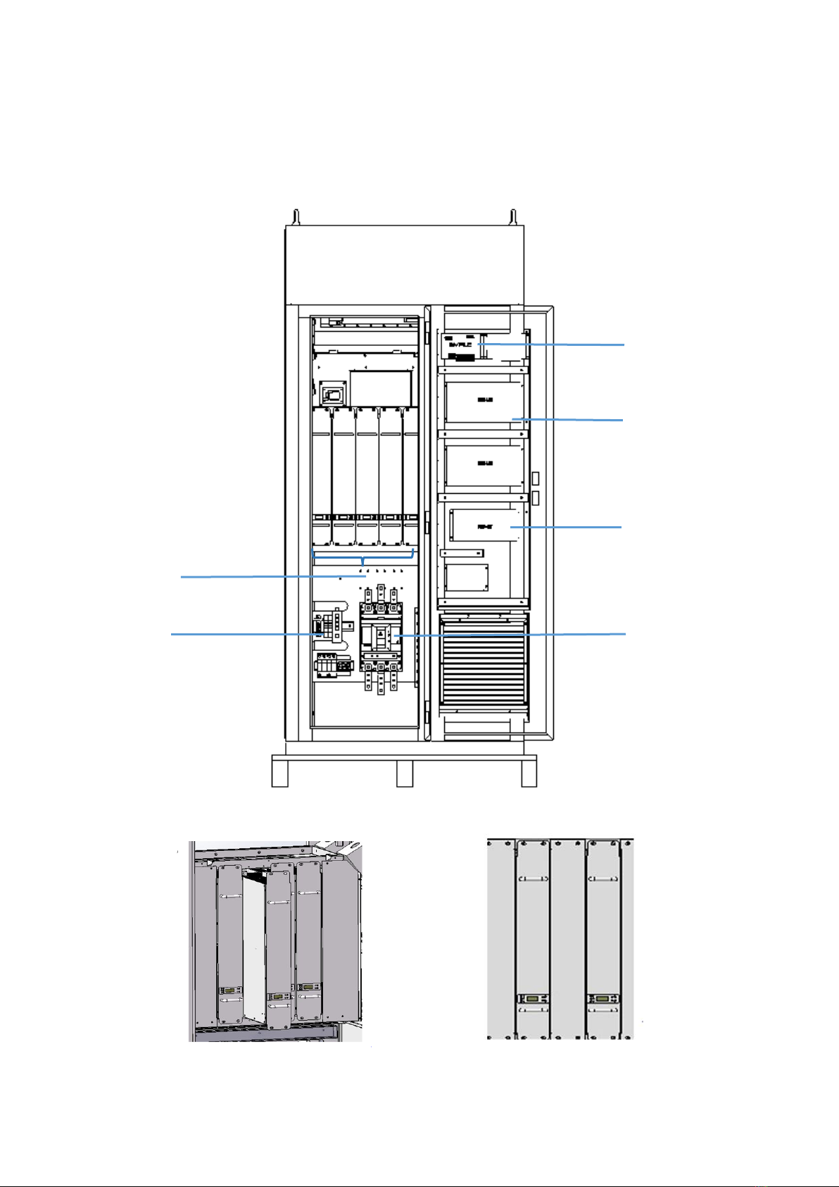
Internal view
1 Charging status LED 2 charging connector
3 RFID Reader 4 Monitor display
5 Emergency stop button 6 Charging module
7 Industrial Switch 8 leakage protector
9 SPD 10 EVPLC
10
6
11
12
7
8
14
9
13

14
11 EVMS-MCM 12 EVMS-MCM2
13 EVMS-CSU 14 AC input switch
3.5 Charger dust screen and air inlet and outlet
Note: Effective ventilation of equipment In order to prevent dust and
obstruct the harmful substances such as PM2.5, the equipment is dust-proofed
by adopting international advanced honeycomb textile technology on the side
Air outlet
Air inlet

15
Note: Please open front door to replace the air filter on the side of
the device. There’s butterfly nut at the side of device (no need of any
tools), just to pull out the air filter for flushing or fan dust
Vibration-proof
Use a screwdriver to remove 4 screws and open
the side door. Please note that when
disassembling, it is recommended that both the
inside and outside doors fall down. It is
recommended that two people operate and
dump carefully
air filte

16
To remove the shockproof components at the bottom of the cabinet, you need to open the rear door, left door, and
all of them. Use a wrench to remove the bolts at the bottom of the cabinet and remove the wooden base. The
installation of the DC charger adopts the method of lower cable entry, the pile body is aligned with the hole,
placed on the cement base, fixed with 6 M12*60 anchor bolts, tightened and locked;

17
3.6 Charger diagram

18
3.7 Input Connection Terminals
Note: For safety, AC input wiring is recommended to use 150 mm2 cable! The wiring is directly connected to the
upper port of the terminal, from left to right: A, B, C. Neutral and Grounding are on the right side of the
circuit breaker.Circuit breaker has type A RCD function,RCD rated residual operating current is 30 mA.
A, B, C, Neutral, Grounding input
terminal wiring
19
3.8 Install and remove the main power module
Charging
module
EVMS-MCM
EVMS-CSU
EV-PLC
Switch start state After wiring, start
the main input switch

20
The installation steps of the main power module are as follows:
1. Insert the AC input and DC output of the cabinet into the corresponding module position;
2. Fix the module to the cabinet through the fixing holes on the upper and lower front panel of
the module;
NOTE!
After the module is installed in the system, please set the address of the
module as "- -01", "- -02", "- -03" and so on in order from left to right.
3.9 After the initial setup boot
Before the system boot, check whether the module is installed, whether the AC input wiring is
correct, after all the preparations are completed, turn on all the switches, a module address bits
are set in accordance with 5.2 after power, and the background set in accordance with 8.1.
3.10 Charging status indicator
With luminous and indicating function, the charger is convenient for customers to conduct
charging operations at night. Three-color indicator: red, yellow, green.
1) Red light indicates fault and alarm status; it will not light on when charger work normally.
2) Yellow light indicates the load is charging.
3)Green light indicates that the battery is fully charged; the charger is in standby mode.
3.11 Emergency stop button
There’s emergency stop button above card billing area. When the charger fails, user can press
the emergency stop button, which make the charger output disconnected, meanwhile the
indicator light keeps to be red. After corresponding troubleshooting, the emergency stop button
will restore by rotated to the right.
This manual suits for next models
1
Table of contents
Popular Automobile Accessories manuals by other brands


Kuda-Phonebase
Kuda-Phonebase 291750 Installation instruction

Over Armour Offroad
Over Armour Offroad KU-X900-FC04 Instructions for Installation and Care

bosal
bosal 027201 FITTING INSTRUCTION

Hook
Hook 420516 manual

Connects2
Connects2 CAM-MB2-AD instruction manual

Royal Rascals
Royal Rascals XLR-5 Installation instructions and tips