SH1000/513TC- SH1400/610TC 1.3 - 2012 15
Montering av hydraulikkmotor og kobling
N
Referer til illustrasjonene Fig 1a og 1b
1. Plasser nederste del av den eksible koblingen (5) på
kileporet på girhusakselen. Ikke stram til.
2. Monter øvre motorbrakett (2) til nedre del (1) med de 8
medfølgende bolter (4) og låseskiver(3). Trekk til med 86Nm
3. Plasser koblingens gummi/plastdel (6) på nederdelen(5)
4. Monter koblingens øvre del (7) på hydraulikkmotorens (10)
aksel og stram festeskruen lett slik at den ikke faller av, men
fremdeles kan beveges.
5. Plasser hydraulikkmotoren (10) på den øvre braketten (2).
Kontroller at koblingens deler går i inngrep. Dette gjøres
enklest ved å dreie motoren om dens vertikale akse.
6. Sentrer koblingens deler mellom girhuset og motorens ens i
henhold til Fig. 1b
7. Når koblingen er sentrert, fjern motoren (10) og stram
settskruen på koblingens øvre del med følgende moment:
Nav med kilespor - 67Nm, Nav med splines, SH1000 - 67Nm,
Nav med splines, SH1400 - 120Nm
8. Løft den nederste delen av koblingen slik at den ligger tett
opptil plast/gummidelen (6). NB: Koblingen må ikke utsettes
for aksiell last.
9. Stram til settskruene på koblingens nedre del (5) med 25Nm
10. Roter propellene for hånd for å sjekke at koblingen roterer fritt
I visse tilfeller (ved grunne installasjoner, ske / arbeidsfartøy)
anbefaler vi å beskytte propell og girhus ved å montere et gitter foran
tunnelåpningene (Fig. 2). Det er da meget viktig å beholde strømlin-
jeformen, og å begrense gitteret til et minimum. Feil installasjon kan
begrense skyvekraften med 15%
NB ! Påfør bunnstoff på girhus og propell for å unngå vekst som
kan virke sterkt hemmende på thrusterens effekt. Anoder,
propellaksling og tetninger skal ikke stoffes.
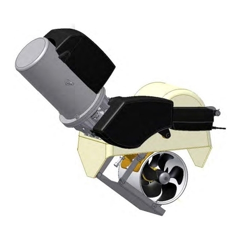
Refer to the illustrations Fig 1a & 1b
1. Insert the lower coupling hub (5) onto the key way of the gear
housing drive shaft. Do not tighten at this stage.
2. Mount the upper bracket (2) to the lower bracket (1) with the 8
securing bolts (4) and lock washers (3).Torque load to 86 Nm.
3. Place the coupling rubber/hard plastic spider (6) onto the
lower hub (5).
4. Insert the upper coupling hub(7) onto the motor(10) shaft and
lightly tighten its set screw, ensuring it maintains its position
but still can be moved on the shaft.
5. Place the hydraulic motor (10) onto the upper bracket (2)
ensuring the coupling hubs and spider engage. This can be
achieved by simply rotating the motor (10) around its vertical
axis.
6. Gain access to the coupling assembly through a upper
bracket (2) side opening. Adjust to centralize the exible
coupling assembly between the gear housing and hydraulic
motor ange. Refer to illustration Fig 1b.
7. With the nal position of the upper coupling hub(7)
established, remove the motor (10) and torque load the upper
coupling(7) set screw to; Key way hub - 25Nm, Splined hub
SH1000 - 67Nm, splined hub SH1400 - 120 Nm.
8. Gain access through a side opening of the upper bracket(2)
and lift the lower coupling hub(5) so it ts rmly against the
coupling spider(6). NB. The exible coupling must not be
subject to a axial load.
9. Torque load lower coupling key way hub (5) set screws to 25
Nm.
10. Rotate the propellers by hand and check the exible coupling
assembly for complete range & freedom of movement.
In some cases (shallow installation or workboat / shinENoat only)
we recommend to protect the propeller by mounting a grid in the
tunnel opening (Fig. 2). It is important to keep a grid to a mini-
mum and as streamlined for the thrusters waterow as possible,
as it can decrease the effect of the thrusters up to 15%.
NB ! Paint the gearhouse and propeller with antifouling for pro-
pellers to prevent growth of barnacles or similar which would
reduce the performance dramatically. Do not paint the pro-
peller shaft, the anodes or the end face of the gearhouse.
Fitting the hydraulic motor and coupling
EN
SLEIPNER MOTOR AS
SLEIPNER MOTOR AS
SH100/185T- SH160/215T - SH240/250TC - SP 300 HYD - SH420/386TC - SH550/386TC 2.9 - 2009 18
SH100/185T- SH160/215T -SH240/250TC - SP 300 HYD - SP 550 HYD 2.6 - 2008
Einbau des Hydraulikmotors
D
1. Die 4 Bolzen in der Motorhalterung enfernen.
2. Die Antriebsachse im Getriebegehäuse und die Motorachse
so drehen, daß die elastische Kupplung dazwischen paßt.
Die Befestigungsschrauben im unteren Teil der elastischen
Kupplung lösen. Den Gummiring ganz in den unteren Teil der
elastischen Kupplung einschieben.
3. Den Motor mit seiner Adapterplatte vorsichtig auf die Antriebs-
achse und die Motorhalterung aufsetzen.
Den Motor mit Adapterplatte auf die Motorhalterung stezen.
Der Gummiring muß sich dabei ganz in den oberen Teil der
elastischen Kupplung schieben.
4. Mit den 4 Bolzen Motor und Motorhalterung lose
verschrauben.
5. Mit den 4 Bolzen Motor/Adapterplatte und Motorhalterung
verschrauben. Anzugsmoment: 33 Nm (24 lb/ft)
6. Den Gummiring ganz in den unteren Teil der elastischen
Kupplung einschieben und zusammen in den oberen Teil
der elastischen Kupplung schieben. Der Gummiring muß
vollkommen im oberen Teil sitzen, darf aber nicht zusammen
gequetscht sein (17 mm). Den unteren Teil mit den beiden
Befestigungsschrauben in neuer Position festschrauben.
7. Überprüfen Sie, ob die beiden Bolzen, die den Motor an der
Adapterplatte befestigen, mit 17 Nm. festgezogen sind.
Wir empfehlen auf die Befestigungsschraube im unteren Teil
der elastischen Kupplung Locktite o.ä. aufzutragen. Die obere
Befestigungsschraube ist bereits mit Locktite befestigt.
8. Überprüfen, ob sich die Propeller frei im Tunnel drehen
lassen. Aufgrund der Getriebeübersetzung und des Motors
sollte das Systemdies etwas schwergängig sein.
9. Installieren Sie einen Drainageschlauch.
In manchen Fällen, z.B. bei achem Rumpf oder im gerwerblichen
Einsatz (z.B. Fischfang) empfehlen wir, den Propeller durch
ein Gitter vor der Tunnelöffnung zu schützen (Fig. 1). Dieses
sollte auf ein Minimum beschränkt und so stromlinienförmig
wie möglich sein, da die Leistung des Thrusters bis zu ca. 10%
reduziert wird.
NB ! Wir empfehlen, auf das Getriebegehäuse Anti-Fouling
aufzutragen. Nicht auf die Propellerachse, Zinkanoden oder
den Verschluß des Getriebegehäuses auftragen.
1. Remove the 4 bolts in the motorbracket.
2. Turn the driveshaft in the gearhouse and the motorshaft so
the key in the shaft and the keyway in the exible coupling are
in-line.
3. Slide the motor with its pretted adaptor plate and pretted
exible coupling onto the driveshaft and the motor bracket
gently.
4. Fasten the motor loosely to the bracket with the provided
bolts.
5. Fasten the adaptor plate rmly to the bracket with the
provided screws. Tighten the screws with a torque of 33 Nm
(24 lb/ft).
7. Check the bolts holding the hydraulic motor to its adaptor
plate by tightening them with a torque of 17 (12,4lb/ft) Nm.
8. Check the system by turning the propeller, it will be a little
hard to turn (because of the gear reduction and the motor),
but you should be able to turn it by hand.
9. Make sure to install the drain hose.
In some cases (shallow installation or workboat / shingboat only)
we recommend to protect the propeller by mounting a grid in the
tunnel opening (Fig. 1). It is important to keep a grid to a mini-
mum and as streamlined for the thrusters waterow as possible,
as it can decrease the effect of the thrusters up to 10%.
NB ! Paint the gearhouse and propeller with antifouling for
pro-pellers to prevent growth of barnacles or similar which
would reduce the performance dramatically. Do not paint
the pro-peller shaft, the zincanodes or the end face of the
gearhouse.
Fitting the hydraulic motor
GB
18
Fig. 1
17mm
Bolt tightening force (4x):
33 Nm (24 lb/ft)
Fig. 1a Fig. 1b Fig. 2
1: Lower bracket
2: Upper bracket
3: Lock washers, bracket (8 pcs)
4: Bolts, bracket (8 pcs)
5: Coupling, lower part
6: Coupling, spider
7: Coupling, upper part
(with key way or splines according
to motor type)
8: Lock washers, motor (4 pcs)
9: Bolts, motor (4 pcs)
10: Hydraulic motor
11: Oil feed nipple
12: Oil tube
13: Oil tank