22955 82020
-
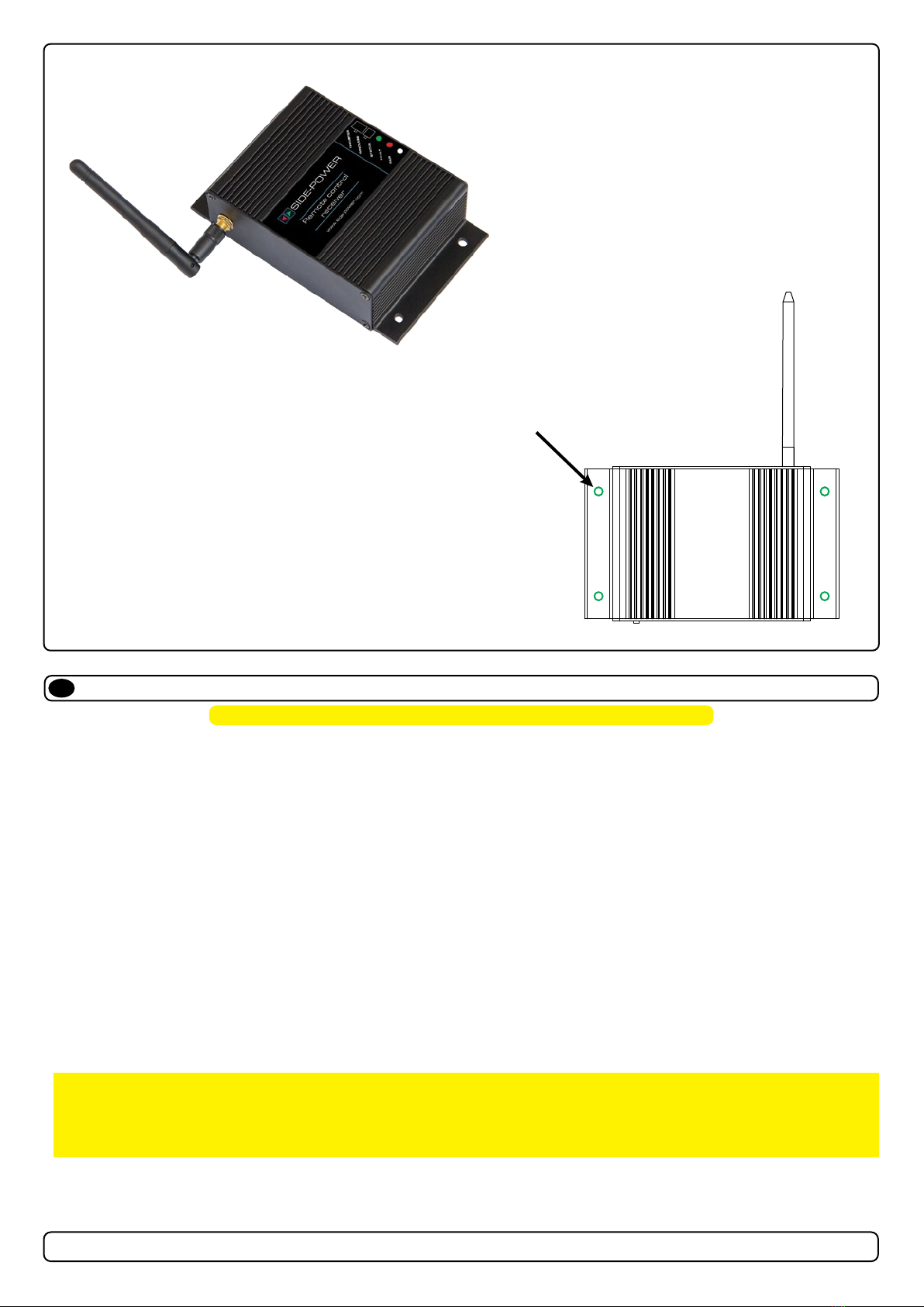
RCT 20E, 21E, 22E, 23E & REMOTE RECEIVER
DECLARATION OF CONFORMITY
Sleipner Motor AS
P.O. Box 519, Arne Svendsensgt. 6-8
N-1612 Fredrikstad, Norway
Declare that this product with accompanying standard control systems complies with
the essential health and safety requirements according to:
DIRECTIVE 2013/53/EU
DIRECTIVE 2014/30/EU
DIRECTIVE 2014/35/EU
MC_0020
Considerations and Precautions ........................................... 3
Signals Considerations and Precautions.............................. 3
Installation Manual
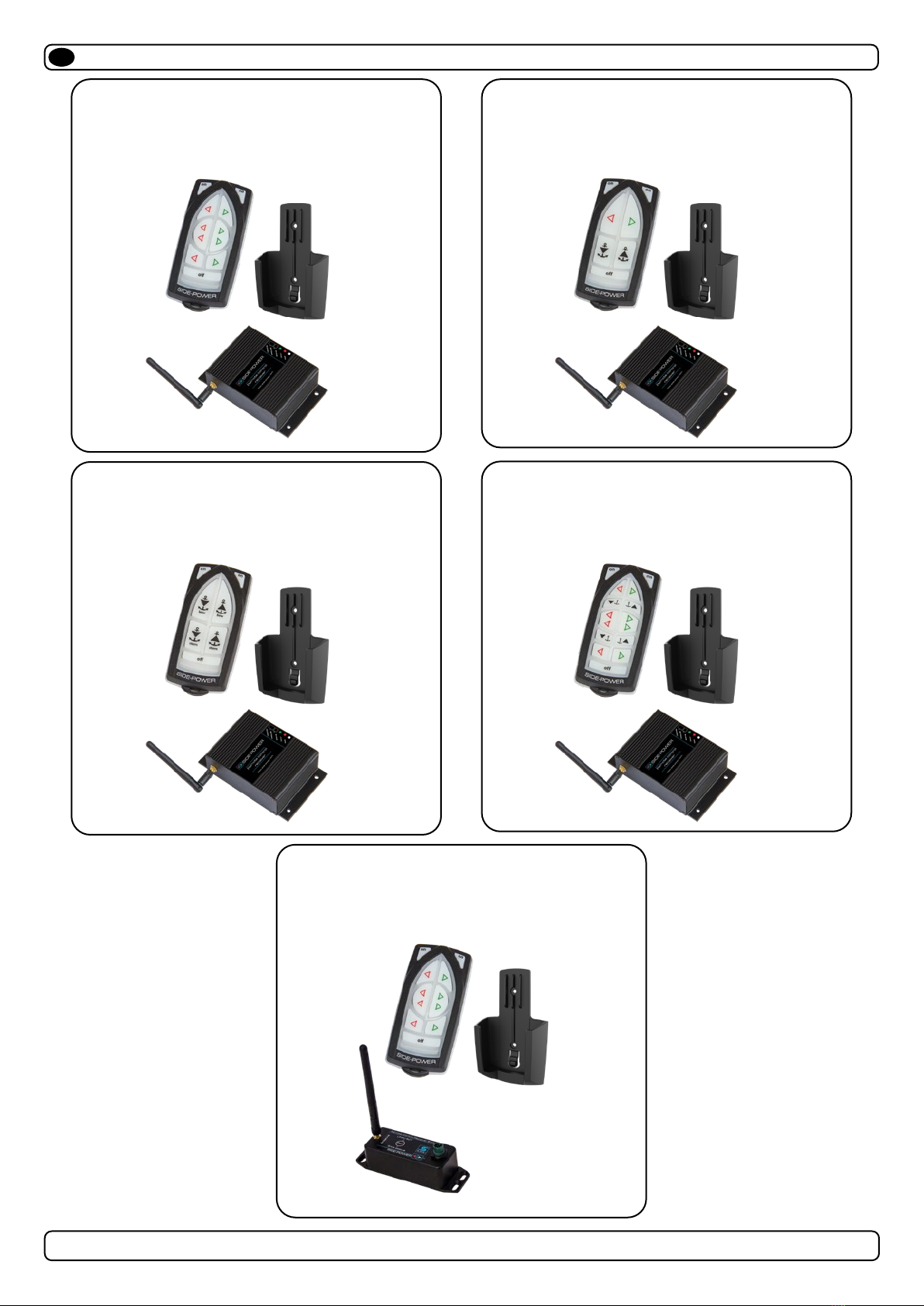
Remote Control Kits ................................................................. 4
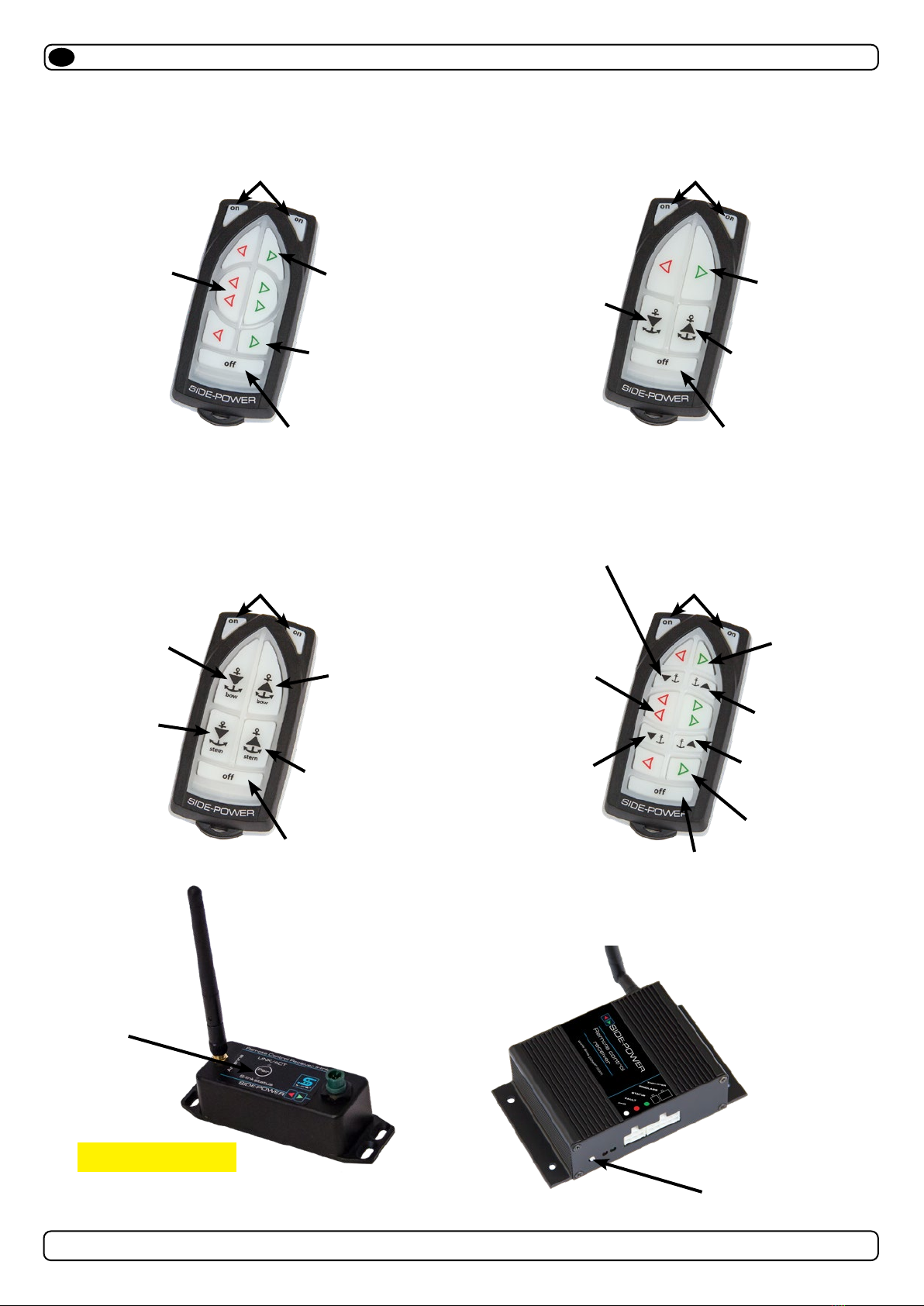
Panel Layout & Functions ......................................................... 5
Technical Specications ............................................................ 6
S-Link Technical Specications ................................................ 6
Receiver Installation ................................................................. 7
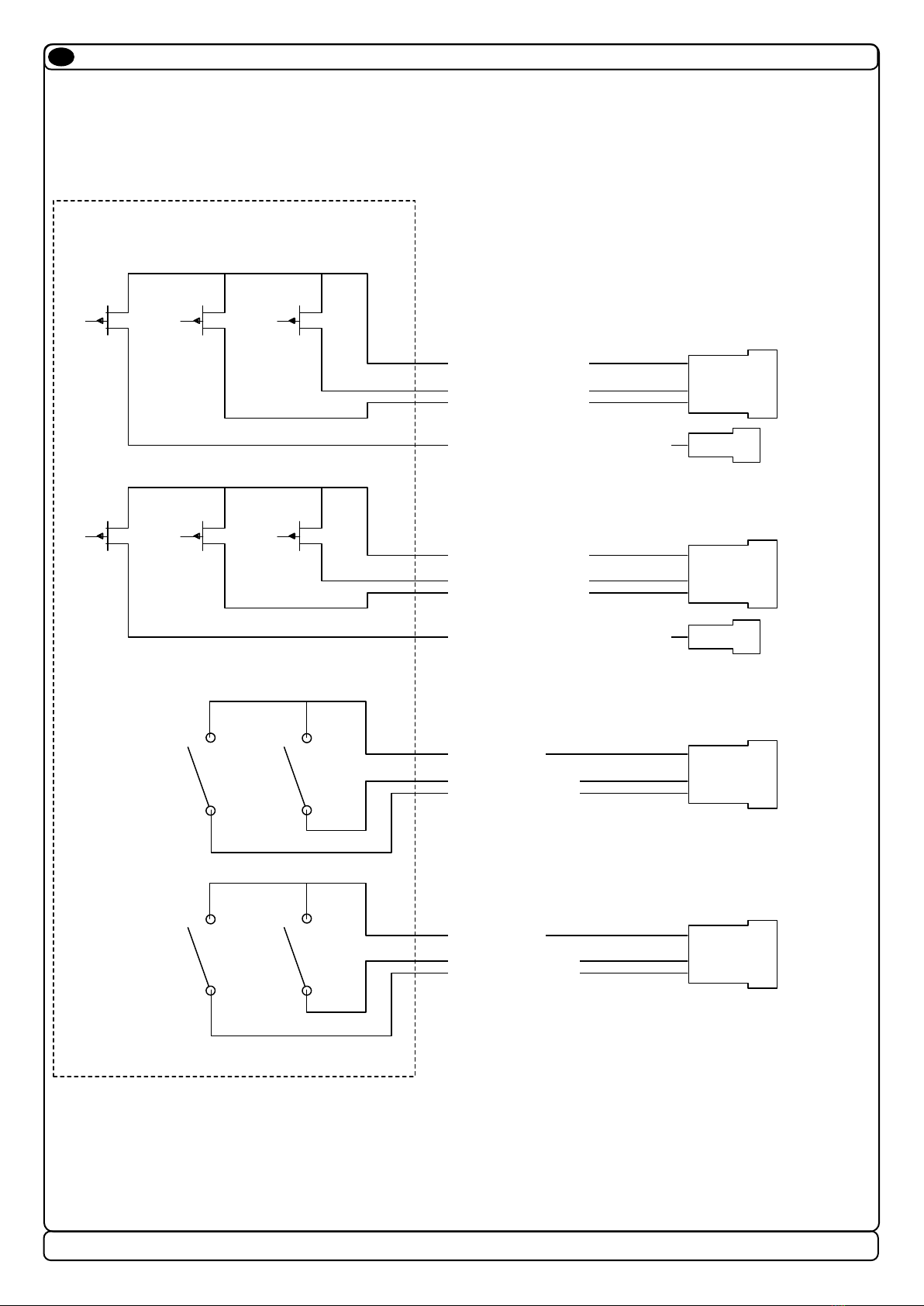
Technical Wiring Diagram ......................................................... 8
Output Signals Diagram ............................................................ 9
Programming Additional Transmitters/ Remote Controls......... 10
S-Link Receiver Installation..................................................... 11
Technical Wiring Diagram........................................................ 12
S-Link Receiver Installation..................................................... 13
Transmitter Installation and Battery Replacemnet................... 14
User Manual
Important Thruster User Considerations and Precautions ...... 15
Thruster Operation .......................................................... 16 - 17
Transmitter LED Operation and Alarm Indication .................... 18
Receiver LED Indicator............................................................ 18
S-Link Transmitter LED Operation and Alarm Indication......... 18
S-Link Receiver LED Indicator ................................................ 18
Contents
EN
MC_0105
Considerations and Precautions
EN
IMPORTANT
If installing S-link products DO NOT connect any other control equipment to the S-link controlled products except Side-Power original
S-link products or via a Side-Power supplied interface product made for interfacing with other controls. Any attempt to directly control or
at all connect into the S-link control system without the designated and approved interface will render all warranties and responsibilities
for the complete line of Side-Power products connected void and null. If you are interfacing by agreement with Sleipner and through a
designated Side-Power supplied interface, you are still required to also install at least one original Side-Power control panel to enable
effi cient troubleshooting if necessary.
It is the installers responsibility
When installing Side-Power equipment to follow the outlined regulations/ classi cation rules (electrical/ mechanical) according to
international or special national regulations. Instructions in this guide cannot be guaranteed to comply with global electric/ mechanic
regulations/ classi cation rules.
It is the installers responsibility
To follow all health and safety laws in accordance with their local outlined regulations/ classi cation rules.
Before installation, it is important that the installer reads this guide to ensure necessary acquaintance with this product.
The recommendations made in this manual are guidelines ONLY, and Sleipner Motor AS (Side-Power) strongly recommend that
before installation, advice is obtained from a naval architect familiar with the particular vessel and regulations/ classi cations.
This manual is intended to support educated/ experienced staff and is therefore not suffi cient in all details for professional
installation. (NB: These instructions are only general instruction. If you are not skilled to do this work, please contact professional
installers for assistance.)
All electrical work must be done by a licensed professional.
IMPORTANT
Faulty installation of the tunnel, thruster or panel will render all warranty given by Sleipner Motor AS void. MC_0038
MC_0211
Signals Considerations and Precautions
EN
IMPORTANT
Sleipner has developed remote controls with approval in the EU and US markets. However, it is the Importers responsibility to comply with
all restrictions and legislation on radio signals in the country to which it is imported.
Products
SM126344 | RCT-23E - Fjernkontrollsend.dbl.vins/thr
SM126317 | RC-21E - Fjernkontrollsett baug/vinsj
SM126428 | RC-23E - Fjernkontroll dbl.vinsj/thrust
SM126315 | RCT-21E - Fjernkontrollsender baug/vinsj
SM126335 | RC-20E - Fjernkontrollsett baug og hekk
SM126327 | RC-22E - Fjernkontrollsett dbl. vinsj
SM126251 | RCR-2E - Fjernkontrollmottaker
SM904984 | RCT-20E - Fjernkontrollsender baug/hekk
SM126321 | RCT-22E - Fjernkontrollsender dbl. vinsj