3
5488 72 0 21
-
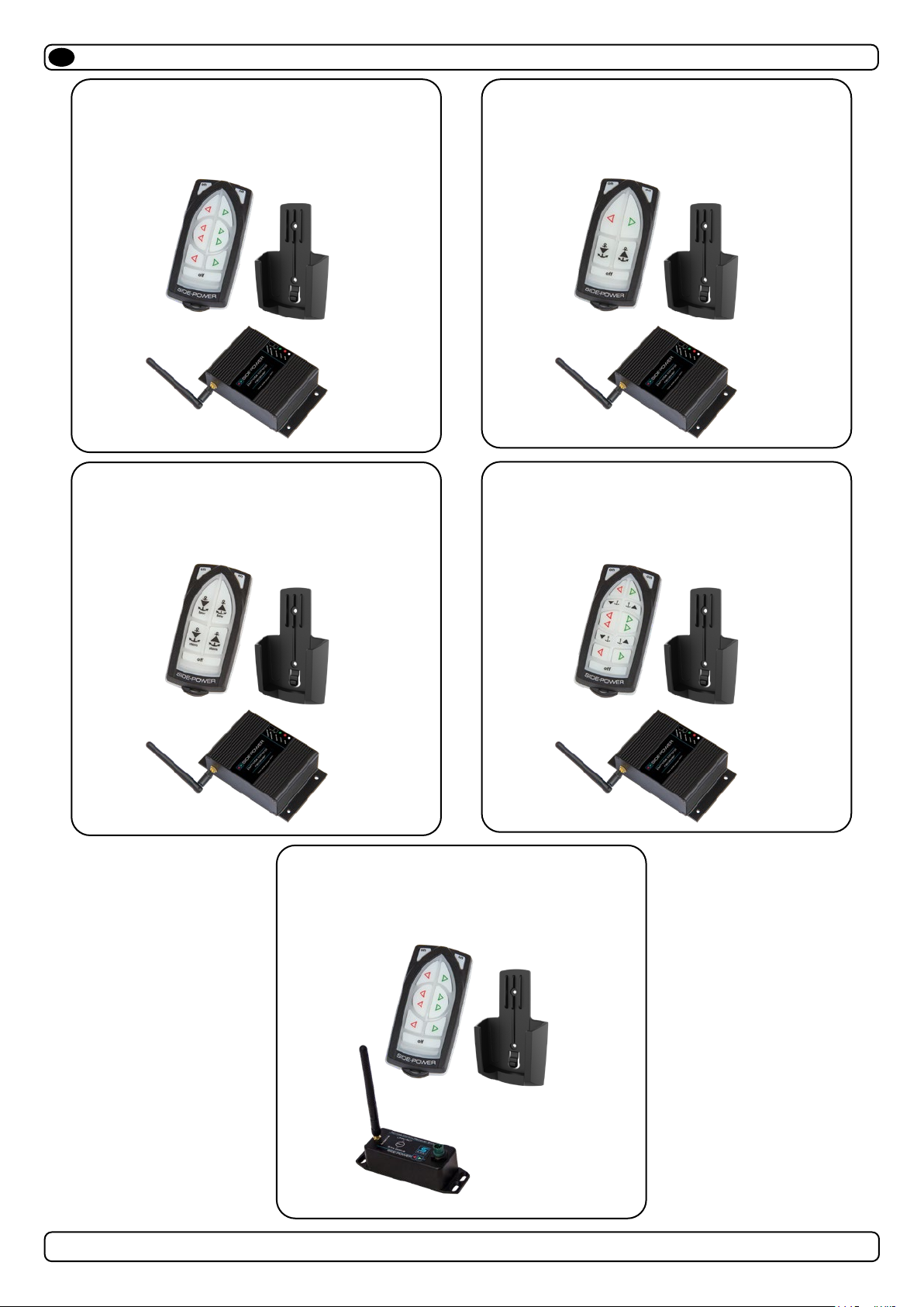
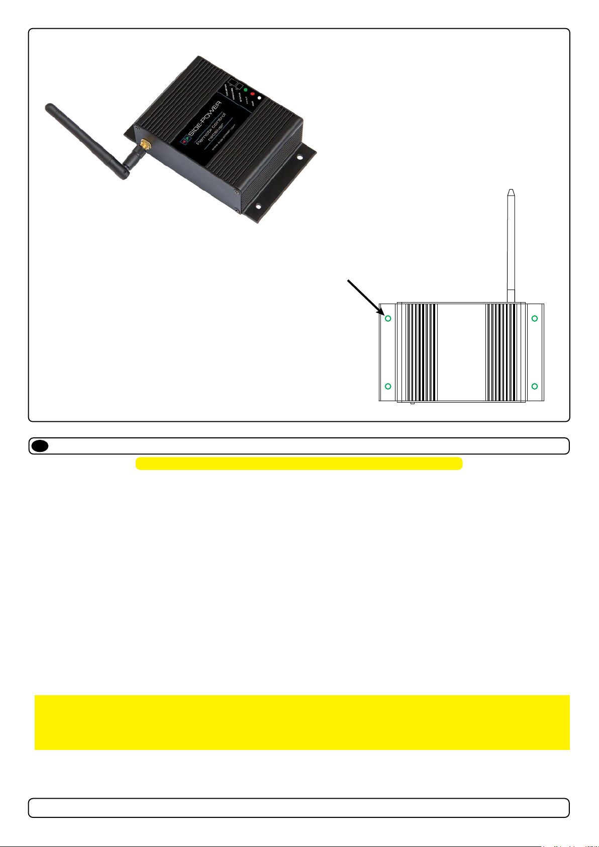
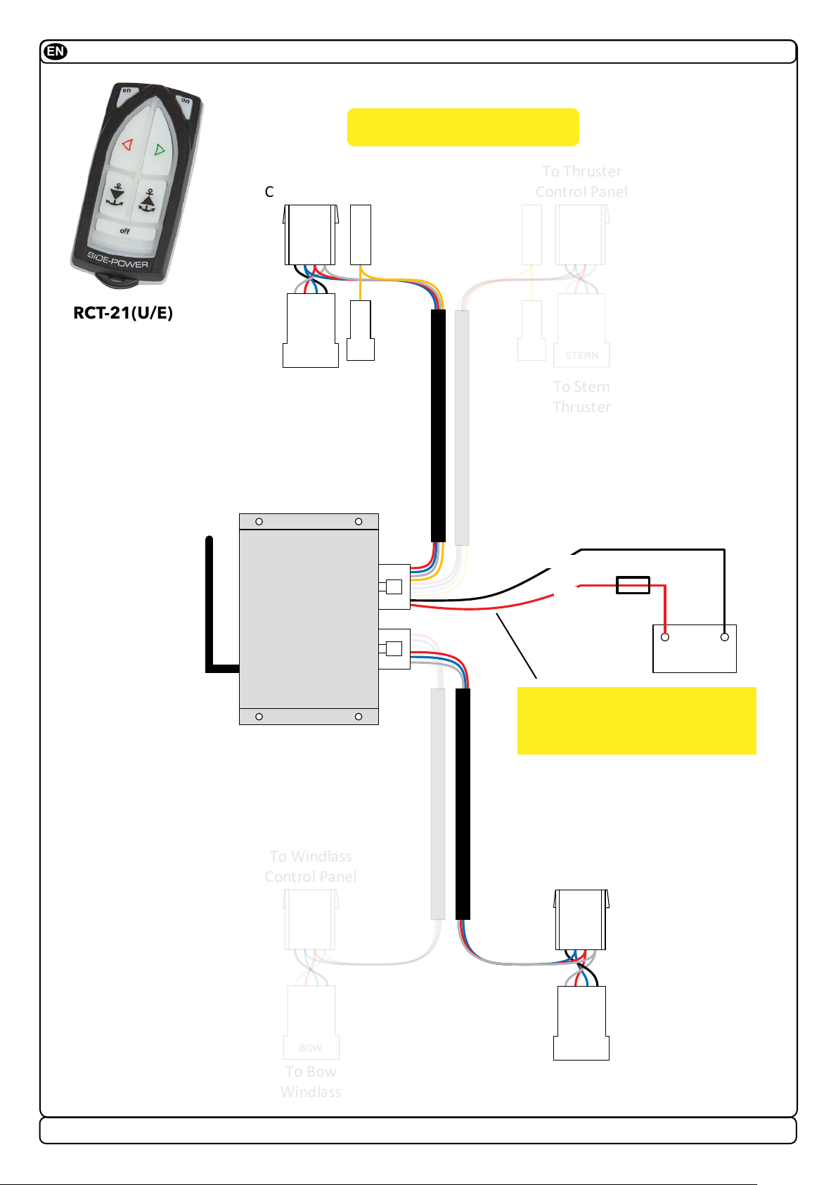
RCT 20U, 21U, 22U, 23U & REMOTE RECEIVER
MC_0105
Considerations and Precautions
EN
IMPORTANT
If installing S-link products DO NOT connect any other control equipment to the S-link controlled products except Side-Power original
S-link products or via a Side-Power supplied interface product made for interfacing with other controls. Any attempt to directly control or
at all connect into the S-link control system without the designated and approved interface will render all warranties and responsibilities
for the complete line of Side-Power products connected void and null. If you are interfacing by agreement with Sleipner and through a
designated Side-Power supplied interface, you are still required to also install at least one original Side-Power control panel to enable
effi cient troubleshooting if necessary.
It is the installers responsibility
When installing Side-Power equipment follow the outlined regulations/ classi cation rules (electrical/ mechanical) according to
international or special national regulations. Instructions in this guide cannot be guaranteed to comply with global electric/ mechanic
regulations/ classi cation rules.
Follow all health and safety laws in accordance with their local outlined regulations/ classi cation rules.
Before installation, it is important that the installer reads this guide to ensure necessary acquaintance with the product.
The recommendations made in this manual are guidelines ONLY, and Sleipner Motor AS (Side-Power) strongly recommend that
before installation, advice is obtained from a naval architect familiar with the particular vessel and regulations/ classi cations.
This manual is intended to support educated/ experienced staff and is therefore not suffi cient in all details for professional
installation. (NB: These instructions are only general instruction. If you are not skilled to do this work, please contact professional
installers for assistance.)
All electrical work must be done by a licensed professional.
Faulty installation of Sleipner products will render all warranty given by Sleipner Motor AS void. MC_0038
MC_0211
Signals Considerations and Precautions
EN
IMPORTANT
Sleipner has developed remote controls with approval in the EU and US markets. However, it is the Importers responsibility to comply with
all restrictions and legislation on radio signals in the country to which it is imported.
Regulatory Information
EN MC_0227
FCC statements
Changes or modi cations to the equipment not expressly approved by the party responsible for compliance could void the user’s authority to operate the
equipment.
This device complies with Part 15 of the FCC Rules. Operation is subject to the following two conditions: (1) this device may not cause harmful interfer-
ence, and (2) this device must accept any interference received, including interference that may cause undesired operation.
NOTE: This equipment has been tested and found to comply with the limits for a Class B digital device, pursuant to Part 15 of the FCC Rules. These
limits are designed to provide reasonable protection against harmful interference in a residential installation. This equipment generates, uses and can
radiate radio frequency energy and, if not installed and used in accordance with the instructions, may cause harmful interference to radio communica-
tions. However, there is no guarantee that interference will not occur in a particular installation.
If this equipment does cause harmful interference to radio or television reception, which can be determined by turning the equipment off and on, the
user is encouraged to try to correct the interference by one or more of the following measures:
- Reorient or relocate the receiving antenna.
- Increase the separation between the equipment and receiver.
- Connect the equipment into an outlet on a circuit diff erent from that to which the receiver is connected.
- Consult the dealer or an experienced radio/TV technician for help.
ISED statements
This Device complies with Industry Canada License-exempt RSS standard(s). Operation is subject to the following two conditions: (1) this device may
not cause interference, and (2) this device must accept any interference, including interference that may cause undesired operation of the device.
Le présent appareil est conforme aux CNR d’Industrie Canada applicables aux appareils radio exempts de licence. L’exploitation est autorisée aux deux
conditions suivantes : (1) l’appareil ne doit pas produire de brouillage ; (2) l’appareil doit accepter tout brouillage radioélectrique subi, même si le brouil-
lage est susceptible d’en compromettre le fonctionnement.