Side-Power SE 40/125S2 IP User manual

Made in Norway
©Sleipner Motor AS 2018
SE 40/125S2 IP
Ignition Protected
thruster assembly
SLEIPNER MOTOR AS
P.O. Box 519
N-1612 Fredrikstad
Norway
www.side-power.com
Installation and user manual
Keep this
manual onboard !
SIDE-POWER
Thruster Systems
Document id: 5456
Revision: 2

2
SE 40/125S2 ignition protected thruster assembly 5456-2 - 2018
Technical specications............................................................. 2
Planning & important precautions.............................................. 3
Stern thruster installation considerations................................... 3
Tunnel installation ..................................................................... 5
Stern tunnel bolt on installation .............................................. 13
Gearhouse and motorbracket.................................................. 14
Propellers ................................................................................ 15
Electromotor IP assembly........................................................ 16
Electrical installation ............................................................... 17
Control panel and control-leads............................................... 18
Visual wiring diagram .............................................................. 19
Technical wiring diagram ........................................................ 20
Checklist.................................................................................. 21
Important user precautions...................................................... 22
How to use Side-Power thrusters............................................ 23
Maintenance............................................................................ 24
Troubleshooting....................................................................... 25
Warranty statement ................................................................ 26
Parts list................................................................................... 27
Service centres ....................................................................... 20
Contents
SAMSVARSERKLÆRING
Sleipner Motor AS
P.O. Box 519, Arne Svendsensgt. 6-8
N-1612 Fredrikstad, Norway
Erklærer at dette produktet med tilhørende
standard kontrollsystemer er i samsvar med
helse, og sikkerhetskravene i henhold til:
DIRECTIVE 2013/53/EU
DIRECTIVE 2014/30/EU
DIRECTIVE 2014/35/EU
DECLARATION OF CONFORMITY
Sleipner Motor AS
P.O. Box 519, Arne Svendsensgt. 6-8
N-1612 Fredrikstad, Norway
Declare that this product with accompany-
ing standard control systems complies with
the essential health and safety requirements
according to:
DIRECTIVE 2013/53/EU
DIRECTIVE 2014/30/EU
DIRECTIVE 2014/35/EU
FREDRIKSTAD, 20th of January 2018
Arne K Skauen
Managing Director, Sleipner Motor AS

3
SE 40/125S2 ignition protected thruster assembly 5456-2 - 2018
Motor: Custom made reversible DC-motor.
Gearhouse: Seawater resistant bronze. Ballbearing at propellershaft; combination of ballbearing and slide bearing at
driveshaft.
Motor bracket: Seawaterresistant aluminium.
Ignition protection: Conforms to ISO 8846
Propeller: 5-blade Skew-back design "Q-prop" propeller, reinforced composite.
Batteries:
Minimum recommended battery capacity (cold crank capacity by DIN standard)
See table
Max. use: S2 = 3 min. or appr. 7-10% within a limited time frame. All electromotors are protected against overheating.
Safety
:
Electronic time-lapse device protects against sudden change of drive direction. Electric thermal cut-o switch in electromotor
protects against over heating (auto reset when electro motor cools down). Flexible coupling between electro-motor and
driveshaft protects electromotor and gear system if propeller gets jammed. If original Side-Power panel is used, the panel shuts
o automatically 6-9 minutes after last use. Integrated microprocessor monitors solenoids, reducing wear and risk of solenoid
lock-in. Auto-stop of thruster in case of accidental solenoid lock-in or if run signal is continuous for more than 3 minutes.
Technical specications
SIDE-POWER THRUSTER SYSTEMS
Bow Thruster A B C D Emin F Frecommended Gmin Gmax
(mm • in)
SE30/125S2 IP 125 • 4.92 245 • 9.6 226 • 8.9 230 • 9.1 125 • 4.92 92 • 3.6 184 • 7.25 4 • 0.16 5 • 0.20
SE40/125S2 IP 125 • 4.92 245 • 9.6 226 • 8.9 230 • 9.1 125 • 4.92 92 • 3.6 184 • 7.25 4 • 0.16 5 • 0.20
SE50/140S IP 140 • 5.5 TBA TBA TBA 125 • 4.92 92 • 3.6 184 • 7.25 4 • 0.16 5 • 0.20
SE60/185S2 IP 185 • 7.3 270 • 10.6 230 • 9.1 272 • 10.7 150 • 5.91 117 • 4.6 234 • 9.2 4 • 0.16 6 • 0.24
SE80/185S IP 185 • 7.3 376 • 14.8 262 • 10.3 327 • 12.9 200 • 7.87 170 • 6.7 340 • 13.4 6 • 0.24 8 • 0.31
SE100/185T IP 185 • 7.3 451 • 17.8 308 • 12.1 382 • 15.0 200 • 7.87 170 • 6.7 340 • 13.4 6 • 0.24 8 • 0.31
SE120/215T IP 215 • 8.46 451 • 17.8 308 • 12.1 382 • 15.0 215 • 8.46 280 • 11 560 • 22.0 6 • 0.24 8 • 0.31
SE130/250T IP 250 • 9.84 451 • 17.8 308 • 12.1 382 • 15.0 230 • 9.00 280 • 11 560 • 22.0 7 • 0.28 10 • 0.39
SE170/250TC IP 250 • 9.84 451 • 17.8 308 • 12.1 382 • 15.0 250 • 9.84 300 • 11.8 600 • 23.6 7 • 0.28 10 • 0.39
Measurements
EE
GG
D C
SE IP Series tunnel thrusters
SE 30/125S2-IP
IP Series SE 40/125S2-IP SE 50/140S-IP SE 60/185S2-IP
40 • 88
30 • 66
20’ - 28’ • 6 - 8.5
125 • 4.92’’
Single
1.5 • 2
12
9.5 • 21
200
SE30/125S2-IP
SEP30/125S2-12IP
48 • 105
40 • 88
26’ - 34’ • 8 - 10.5
125 • 4.92’’
Single
2.2 • 3
12
10 • 22
300
SE40/125S2-IP
SEP40/125S2-12IP
SEP40/125S2-24IP
73 • 161
60 • 132
29’ - 38’ • 9 - 12
185 • 7.3’’
Single
3.1 • 4
12/24
16 • 35
350/175
SE60/185S2-12IP
SE60/185S2-24IP
SEP60/185S2-12IP
SEP60/185S2-24IP
Thrust at 12V/24V* (kg • lbs)
Thrust at 10.5V/21V* (kg • lbs)
Typical boat size (ft • m)
Tunnel I.D. (mm • in)
Propulsion system
Power at 10.5V/21V* (kw • Hp)
For DC system (V)
Weight (kg • lbs)
Min. Batt. Cap (CCA** 12/24V)
Item Code 12V
Item Code 24V
Item Code 12V PRO
Item Code 24V PRO
62 • 136
50 • 110
27’ - 37’ • 8 - 11
140 • 5.5’’
Single
2.4 • 3.2
12/24
15 • 33
350/175
SE50/140S-12V-IP
SE50/140S-24V-IP
SEP50/140S-12V-IP
SEP50/140S-24V-IP
*Note 1 - See page 47
F
39
VVI
Stern thruster I II IIImin IVmax V VI Tunnel
(mm • in) Length
SE30/125S2 IP 220 • 8.66 190 • 7.48 135 • 5.1 14 • 0.55 160 • 6.3 217 • 8.5 197 • 7.76
SE40/125S2 IP 220 • 8.66 190 • 7.48 135 • 5.31 14 • 0.55 160 • 6.3 217 • 8.5 197 • 7.76
SE60/185S2 IP 265 • 10.43 256 • 10.1 150 • 5.91 35 • 1.38 200 • 7.8 300 • 11.8 337 • 13.27
SE80/185S IP 399 • 15.70 256 • 10.1 200 • 7.87 54 • 2.13 200 • 7.8 300 • 11.8 337 • 13.27
SE100/185T IP 407 • 16.02 256 • 10.1 200 • 7.87 44 • 1,73 200 • 7.8 300 • 11.8 337 • 13.27
SE120/215T IP 407 • 16.02 300 • 11.8 215 • 8.46 44 • 1.73 200 • 7.8 300 • 11.8 330 • 13.00
SE130/250T IP 407 • 16.02 340 • 13.4 250 • 9.84 60 • 2.36 200 • 7.8 350 • 13.8 350 • 13.87
SE170/250TC IP 407 • 16.02 340 • 13.4 250 • 9.84 60 • 2.36 200 • 7.8 350 • 13.8 350 • 13.87
SE 120/215T-IP SE 130/250T-IP SE 170/250TC-IP
139 • 306
120 • 264
42’ - 60’ • 13 - 18
215 • 8.46’’
Twin
6.4 • 8.55
24
34 • 74
400
SE120/215T-IP
SEP120/215T-IP
160 • 352
130 • 284
42’ - 62’ • 13 - 19
250 • 9.8’’
Twin
6.5 • 8.7
12/24
37 • 77
750/400
SE130/250T-12V-12IP
SE130/250T-24V-24IP
SEP130/250T-12V-12IP
SEP130/250T-24V-24IP
210 • 462
170 • 374
50’ - 70’ • 15 - 22
250 • 9.8’’
Twin Counter rot.
8 • 10.7
24
44 • 97
550
SE170/250TC-IP
SEP170/250TC-IP
SE 80/185T-IP SE 100/185T-IP
96 • 212
80 • 176
35’ - 48’ • 10 - 15
185 • 7.3’’
Twin
4.4 • 6
12/24
20 • 44
550/300
SE80/185T-12V-12IP
SE80/185T-24V-24IP
SEP80/185T-12V-12IP
SEP80/185T-24V-24IP
116 • 256
100 • 220
35’ - 55’ • 12 - 17
185 • 7.3’’
Twin
6.3 • 8.4
12/24
31 • 68
750/400
SE100/185T-12V-12IP
SE100/185T-24V-24IP
SEP100/185T-12V-12IP
SEP100/185T-24V-24IP
SIDE-POWER THRUSTER SYSTEMS
Bow Thruster A B C D Emin F Frecommended Gmin Gmax
(mm • in)
SE30/125S2 IP 125 • 4.92 245 • 9.6 226 • 8.9 230 • 9.1 125 • 4.92 92 • 3.6 184 • 7.25 4 • 0.16 5 • 0.20
SE40/125S2 IP 125 • 4.92 245 • 9.6 226 • 8.9 230 • 9.1 125 • 4.92 92 • 3.6 184 • 7.25 4 • 0.16 5 • 0.20
SE50/140S IP 140 • 5.5 TBA TBA TBA 125 • 4.92 92 • 3.6 184 • 7.25 4 • 0.16 5 • 0.20
SE60/185S2 IP 185 • 7.3 270 • 10.6 230 • 9.1 272 • 10.7 150 • 5.91 117 • 4.6 234 • 9.2 4 • 0.16 6 • 0.24
SE80/185S IP 185 • 7.3 376 • 14.8 262 • 10.3 327 • 12.9 200 • 7.87 170 • 6.7 340 • 13.4 6 • 0.24 8 • 0.31
SE100/185T IP 185 • 7.3 451 • 17.8 308 • 12.1 382 • 15.0 200 • 7.87 170 • 6.7 340 • 13.4 6 • 0.24 8 • 0.31
SE120/215T IP 215 • 8.46 451 • 17.8 308 • 12.1 382 • 15.0 215 • 8.46 280 • 11 560 • 22.0 6 • 0.24 8 • 0.31
SE130/250T IP 250 • 9.84 451 • 17.8 308 • 12.1 382 • 15.0 230 • 9.00 280 • 11 560 • 22.0 7 • 0.28 10 • 0.39
SE170/250TC IP 250 • 9.84 451 • 17.8 308 • 12.1 382 • 15.0 250 • 9.84 300 • 11.8 600 • 23.6 7 • 0.28 10 • 0.39
Measurements
EE
GG
D C
SE IP Series tunnel thrusters
SE 30/125S2-IP
IP Series SE 40/125S2-IP SE 50/140S-IP SE 60/185S2-IP
40 • 88
30 • 66
20’ - 28’ • 6 - 8.5
125 • 4.92’’
Single
1.5 • 2
12
9.5 • 21
200
SE30/125S2-IP
SEP30/125S2-12IP
48 • 105
40 • 88
26’ - 34’ • 8 - 10.5
125 • 4.92’’
Single
2.2 • 3
12
10 • 22
300
SE40/125S2-IP
SEP40/125S2-12IP
SEP40/125S2-24IP
73 • 161
60 • 132
29’ - 38’ • 9 - 12
185 • 7.3’’
Single
3.1 • 4
12/24
16 • 35
350/175
SE60/185S2-12IP
SE60/185S2-24IP
SEP60/185S2-12IP
SEP60/185S2-24IP
Thrust at 12V/24V* (kg • lbs)
Thrust at 10.5V/21V* (kg • lbs)
Typical boat size (ft • m)
Tunnel I.D. (mm • in)
Propulsion system
Power at 10.5V/21V* (kw • Hp)
For DC system (V)
Weight (kg • lbs)
Min. Batt. Cap (CCA** 12/24V)
Item Code 12V
Item Code 24V
Item Code 12V PRO
Item Code 24V PRO
62 • 136
50 • 110
27’ - 37’ • 8 - 11
140 • 5.5’’
Single
2.4 • 3.2
12/24
15 • 33
350/175
SE50/140S-12V-IP
SE50/140S-24V-IP
SEP50/140S-12V-IP
SEP50/140S-24V-IP
*Note 1 - See page 47
F
Responsible installer must
consider and facilitating
enough space and access
regarding installation,
service and maintenance
of the thruster.
SIDE-POWER THRUSTER SYSTEMS
Bow Thruster A B C D Emin F Frecommended Gmin Gmax
(mm • in)
SE30/125S2 IP 125 • 4.92 245 • 9.6 226 • 8.9 230 • 9.1 125 • 4.92 92 • 3.6 184 • 7.25 4 • 0.16 5 • 0.20
SE40/125S2 IP 125 • 4.92 245 • 9.6 226 • 8.9 230 • 9.1 125 • 4.92 92 • 3.6 184 • 7.25 4 • 0.16 5 • 0.20
SE50/140S IP 140 • 5.5 TBA TBA TBA 125 • 4.92 92 • 3.6 184 • 7.25 4 • 0.16 5 • 0.20
SE60/185S2 IP 185 • 7.3 270 • 10.6 230 • 9.1 272 • 10.7 150 • 5.91 117 • 4.6 234 • 9.2 4 • 0.16 6 • 0.24
SE80/185S IP 185 • 7.3 376 • 14.8 262 • 10.3 327 • 12.9 200 • 7.87 170 • 6.7 340 • 13.4 6 • 0.24 8 • 0.31
SE100/185T IP 185 • 7.3 451 • 17.8 308 • 12.1 382 • 15.0 200 • 7.87 170 • 6.7 340 • 13.4 6 • 0.24 8 • 0.31
SE120/215T IP 215 • 8.46 451 • 17.8 308 • 12.1 382 • 15.0 215 • 8.46 280 • 11 560 • 22.0 6 • 0.24 8 • 0.31
SE130/250T IP 250 • 9.84 451 • 17.8 308 • 12.1 382 • 15.0 230 • 9.00 280 • 11 560 • 22.0 7 • 0.28 10 • 0.39
SE170/250TC IP 250 • 9.84 451 • 17.8 308 • 12.1 382 • 15.0 250 • 9.84 300 • 11.8 600 • 23.6 7 • 0.28 10 • 0.39
Measurements
EE
GG
D C
SE IP Series tunnel thrusters
SE 30/125S2-IP
IP Series
SE 40/125S2-IP
SE 50/140S-IP SE 60/185S2-IP
40 • 88
30 • 66
20’ - 28’ • 6 - 8.5
125 • 4.92’’
Single
1.5 • 2
12
9.5 • 21
200
SE30/125S2-IP
SEP30/125S2-12IP
48 • 105
40 • 88
26’ - 34’ • 8 - 10.5
125 • 4.92’’
Single
2.2 • 3
12
10 • 22
300
SE40/125S2-IP
SEP40/125S2-12IP
SEP40/125S2-24IP
73 • 161
60 • 132
29’ - 38’ • 9 - 12
185 • 7.3’’
Single
3.1 • 4
12/24
16 • 35
350/175
SE60/185S2-12IP
SE60/185S2-24IP
SEP60/185S2-12IP
SEP60/185S2-24IP
Thrust at 12V/24V* (kg • lbs)
Thrust at 10.5V/21V* (kg • lbs)
Typical boat size (ft • m)
Tunnel I.D. (mm • in)
Propulsion system
Power at 10.5V/21V* (kw • Hp)
For DC system (V)
Weight (kg • lbs)
Min. Batt. Cap (CCA** 12/24V)
Item Code 12V
Item Code 24V
Item Code 12V PRO
Item Code 24V PRO
62 • 136
50 • 110
27’ - 37’ • 8 - 11
140 • 5.5’’
Single
2.4 • 3.2
12/24
15 • 33
350/175
SE50/140S-12V-IP
SE50/140S-24V-IP
SEP50/140S-12V-IP
SEP50/140S-24V-IP
*Note 1 - See page 47
F
SIDE-POWER THRUSTER SYSTEMS
Bow Thruster A B C D Emin F Frecommended Gmin Gmax
(mm • in)
SE30/125S2 IP 125 • 4.92 245 • 9.6 226 • 8.9 230 • 9.1 125 • 4.92 92 • 3.6 184 • 7.25 4 • 0.16 5 • 0.20
SE40/125S2 IP 125 • 4.92 245 • 9.6 226 • 8.9 230 • 9.1 125 • 4.92 92 • 3.6 184 • 7.25 4 • 0.16 5 • 0.20
SE50/140S IP 140 • 5.5 TBA TBA TBA 125 • 4.92 92 • 3.6 184 • 7.25 4 • 0.16 5 • 0.20
SE60/185S2 IP 185 • 7.3 270 • 10.6 230 • 9.1 272 • 10.7 150 • 5.91 117 • 4.6 234 • 9.2 4 • 0.16 6 • 0.24
SE80/185S IP 185 • 7.3 376 • 14.8 262 • 10.3 327 • 12.9 200 • 7.87 170 • 6.7 340 • 13.4 6 • 0.24 8 • 0.31
SE100/185T IP 185 • 7.3 451 • 17.8 308 • 12.1 382 • 15.0 200 • 7.87 170 • 6.7 340 • 13.4 6 • 0.24 8 • 0.31
SE120/215T IP 215 • 8.46 451 • 17.8 308 • 12.1 382 • 15.0 215 • 8.46 280 • 11 560 • 22.0 6 • 0.24 8 • 0.31
SE130/250T IP 250 • 9.84 451 • 17.8 308 • 12.1 382 • 15.0 230 • 9.00 280 • 11 560 • 22.0 7 • 0.28 10 • 0.39
SE170/250TC IP 250 • 9.84 451 • 17.8 308 • 12.1 382 • 15.0 250 • 9.84 300 • 11.8 600 • 23.6 7 • 0.28 10 • 0.39
Measurements
EE
GG
D C
SE IP Series tunnel thrusters
SE 30/125S2-IP
IP Series SE 40/125S2-IP SE 50/140S-IP SE 60/185S2-IP
40 • 88
30 • 66
20’ - 28’ • 6 - 8.5
125 • 4.92’’
Single
1.5 • 2
12
9.5 • 21
200
SE30/125S2-IP
SEP30/125S2-12IP
48 • 105
40 • 88
26’ - 34’ • 8 - 10.5
125 • 4.92’’
Single
2.2 • 3
12
10 • 22
300
SE40/125S2-IP
SEP40/125S2-12IP
SEP40/125S2-24IP
73 • 161
60 • 132
29’ - 38’ • 9 - 12
185 • 7.3’’
Single
3.1 • 4
12/24
16 • 35
350/175
SE60/185S2-12IP
SE60/185S2-24IP
SEP60/185S2-12IP
SEP60/185S2-24IP
Thrust at 12V/24V* (kg • lbs)
Thrust at 10.5V/21V* (kg • lbs)
Typical boat size (ft • m)
Tunnel I.D. (mm • in)
Propulsion system
Power at 10.5V/21V* (kw • Hp)
For DC system (V)
Weight (kg • lbs)
Min. Batt. Cap (CCA** 12/24V)
Item Code 12V
Item Code 24V
Item Code 12V PRO
Item Code 24V PRO
62 • 136
50 • 110
27’ - 37’ • 8 - 11
140 • 5.5’’
Single
2.4 • 3.2
12/24
15 • 33
350/175
SE50/140S-12V-IP
SE50/140S-24V-IP
SEP50/140S-12V-IP
SEP50/140S-24V-IP
*Note 1 - See page 47
F
39
VVI
Stern thruster I II IIImin IVmax V VI Tunnel
(mm • in) Length
SE30/125S2 IP 220 • 8.66 190 • 7.48 135 • 5.1 14 • 0.55 160 • 6.3 217 • 8.5 197 • 7.76
SE40/125S2 IP 220 • 8.66 190 • 7.48 135 • 5.31 14 • 0.55 160 • 6.3 217 • 8.5 197 • 7.76
SE60/185S2 IP 265 • 10.43 256 • 10.1 150 • 5.91 35 • 1.38 200 • 7.8 300 • 11.8 337 • 13.27
SE80/185S IP 399 • 15.70 256 • 10.1 200 • 7.87 54 • 2.13 200 • 7.8 300 • 11.8 337 • 13.27
SE100/185T IP 407 • 16.02 256 • 10.1 200 • 7.87 44 • 1,73 200 • 7.8 300 • 11.8 337 • 13.27
SE120/215T IP 407 • 16.02 300 • 11.8 215 • 8.46 44 • 1.73 200 • 7.8 300 • 11.8 330 • 13.00
SE130/250T IP 407 • 16.02 340 • 13.4 250 • 9.84 60 • 2.36 200 • 7.8 350 • 13.8 350 • 13.87
SE170/250TC IP 407 • 16.02 340 • 13.4 250 • 9.84 60 • 2.36 200 • 7.8 350 • 13.8 350 • 13.87
SE 120/215T-IP SE 130/250T-IP SE 170/250TC-IP
139 • 306
120 • 264
42’ - 60’ • 13 - 18
215 • 8.46’’
Twin
6.4 • 8.55
24
34 • 74
400
SE120/215T-IP
SEP120/215T-IP
160 • 352
130 • 284
42’ - 62’ • 13 - 19
250 • 9.8’’
Twin
6.5 • 8.7
12/24
37 • 77
750/400
SE130/250T-12V-12IP
SE130/250T-24V-24IP
SEP130/250T-12V-12IP
SEP130/250T-24V-24IP
210 • 462
170 • 374
50’ - 70’ • 15 - 22
250 • 9.8’’
Twin Counter rot.
8 • 10.7
24
44 • 97
550
SE170/250TC-IP
SEP170/250TC-IP
SE 80/185T-IP SE 100/185T-IP
96 • 212
80 • 176
35’ - 48’ • 10 - 15
185 • 7.3’’
Twin
4.4 • 6
12/24
20 • 44
550/300
SE80/185T-12V-12IP
SE80/185T-24V-24IP
SEP80/185T-12V-12IP
SEP80/185T-24V-24IP
116 • 256
100 • 220
35’ - 55’ • 12 - 17
185 • 7.3’’
Twin
6.3 • 8.4
12/24
31 • 68
750/400
SE100/185T-12V-12IP
SE100/185T-24V-24IP
SEP100/185T-12V-12IP
SEP100/185T-24V-24IP

4
SE 40/125S2 ignition protected thruster assembly 5456-2 - 2018
Prior to installation, it is important that the installer reads this guide to ensure necessary acquaintance with this product.
The electromotor assembly must be handled carefully. Do not put it down on the driveshaft.
Beware to keep installation within advised measurements.
We advice to paint the gearhouse and propellers with antifouling. PS! Do not paint the zinc anodes, sealings or propellershafts.
Do not nish the inside of the tunnel with a layer of gelcoat / topcoat or similiar. It is only room for a thin layer of primer and two layers
of anti-fouling between the tunnel and the props.
With the boat on land, only run the thruster for a fraction of a second, as without resistance it will accelerate very fast to a damaging
rpm. Also, while the thruster is in air, make sure to avoid direction changes while the thruster is still running, as it might cause
damage to the thruster.
This manual is intended to support educated / experienced sta and is therefore not sucient in all details for the correct installation.
The thruster IP assembly has been tested to be fully ignition protected so that it can be installed in an area with the possibility of
explosive gases in accordance to ISO 8846.
Do not install the thruster in a position where you need to cut a stiener/stringer/support for the hull integrity without checking with the
boatbuilder that this can be safely done.
When installed in boats approved or classied according to international or special national rules, the installer is responsible for
following the demands in accordance with these regulations / classication rules. The instructions in this guide can not be guaranteed
to comply with all dierent regulations / classication rules.
NB ! Faulty installation of the tunnel, thruster or panel will render all warranty given by Sleipner Motor AS void.
Planning and important precautions
To achieve maximum eect, reliability and durability from your Sidepower stern thruster, a correct installation is very important.
Please follow the instructions carefully, and make sure that all checkpoints are carefully controlled.
Additional considerations for positioning of the stern thruster
Make sure that the stern-tunnel does not disturb the waterow under the hull
Ensure that when installed the thruster does not foul existing equipment inside the boat like steerage links etc.
Make sure that the water ow from the thruster are not interfered too much by sterndrives, trimtabs etc. as this will reduce the thrust
considerably.
It is possible to mount the tunnel o the boat’s centre line if necessary.
If the stern thickness is to much for the thruster in question you can easily remove hull material in the necessary area to t the
thruster. You only have to reduce the stern thickness down to the max. thickness measurement in the drawing.
Stern thruster installation considerations

5
SE 40/125S2 ignition protected thruster assembly 5456-2 - 2018
Master 1
The Thruster should be as far forward as possible (Fig. 1)
Because of the leverage e ect around the boats pivot point, it is
very important for the thrusters actual e ect in the boat to get it as
far forward as possible. The relative distance change from the boats
pivot point to the thruster will be the change of actual thrust for the
boat.
Example :
A: 100kg thrust x 11m leverage = 1100kgm torque to rot. the boat
B: 100kg thrust x 10m leverage = 1000kgm torque to rot. the boat
In position A you will get 10% more thrust to turn the boat around.
The thruster should be placed as deep as possible (Fig. 2)
The tunnel should be placed as deep as possible for two reasons:
1. Thrust will be reduced dramatically due.
2. To get as high as possible a water pressure to get maximum
e ciency from the propeller.
Generally the top of the tunnel should be a minimum of 1/2 x the
tunnel diameter below the waterline. This is an absolute minimum
and we recommend that it is at least 3/4 x tunnel diameter ()
below the waterline. A really good distance is about 1/1 x tunnel
diameter () below the waterline.
When you get the top of the tunnel 30-35 cm* / 1 feet below the
surface, other factors should be considered more important, i.e.
moving the thruster further forward.
Optimal tunnel length
If the tunnel gets too long, the friction inside will reduce the water
speed and thereby the thrust.
If the tunnel gets to short (normally only in the bottom section of
the tunnel) you can get cavitation problems as the water will not
have had time to “straigthen” itself before reaching the propel-
ler (Fig. 3/4). This cavitation will reduce performance as well as
creating a lot of noise.
The optimal tunnel length is 2 to 4 x tunnel diameter and you
should avoid tunnels longer than 6 to 7 times the tunnel diameter
as the performance reduction is then clearly noticeable.
Positioning of the tunnel / thruster
EN Plassering av tunnel og thruster
NO
Tunnelen bør plasseres lengst mulig frem i baugen (Fig. 1)
For å oppnå mest mulig moment rundt båtens dreiepunkt, er det
meget viktig å plassere tunnelen så langt fremme som mulig.
Avstanden fra båtens dreiepunkt til thruster vil ha stor betydning
på thrusterens e ekt.
Eks.:
A: 55kg skyvekraft x 11m moment = 605kgm skyvekraft
B: 55kg skyvekraft x 10m moment = 550kgm skyvekraft
Posisjon A vil gi 10% mer skyvekraft til rotasjon.
Tunnelen skal plasseres dypest mulig (Fig. 2)
Tunnelen skal plasseres så dypt som mulig av to grunner:
1. Så luft ikke suges ned i tunnelen og ødelegger skyvekraften.
2. Ved å øke vanntrykket jobber propellen mer e ektivt.
Hovedregelen er at tunnelen skal plasseres minimum ½ x tun-
nelen dia. under vannlinje. Anbefalt dybde er minst ¾ x dia. under
vannlinje (). Når tunnelen er plassert 33-35 cm under vannlinjen
bør andre faktorer vurderes som viktigere, d.v.s. å plassere tun-
nelen lengre frem.
Optimal tunnel lengde
Dersom tunellen blir for lang vil friksjonen i tunellen reduser vann-
hastigheten og derved e ekten.
Dersom tunellen blir for kort (normalt bare i nedre del av tunel-
len) kan det oppstå kavitasjons problemer da vannet ikke har tid
/ av-stand til å «rette opp strømningsretningen» før det tre er
propellen (Fig. 3&4). Denne kavitasjonen vil redusere e ekten og
lage mye støy.
Den optimale tunell lengden er 2 til 4 ganger tunell diameteren
og dersom tunellen blir så mye som 6 til 7 ganger diameteren i
lengde vil e ekt tapet bli klart merkbart.
10
SP 75 Ti / SP 95 Ti / SP 125 Ti
2.5.1- 2007
Tunnelplazierung soweit vorne wie möglich (Fig. 1)
Um einen möglichst großen Abstand vom Drehpunkt des Schiffes zu
erreichen, ist der Sidepower möglichst weit vorne einzubauen.
Eine Vergrößerung des Abstandes vom Drehpunkt des Schiffes
hat eine direkte Auswirkung auf die verfügbare Schubkraft.
Beispiel :
A: 55kg Schubkraft x 11m = 605kgm zum Wenden des Bootes
B: 55kg Schubkraft x 10m = 550kgm zum Wenden des Bootes
In Beispiel A stehen damit 10% mehr Schubkraft zur Verfügung.
Den Tunnel so tief wie möglich positionieren (Fig. 2)
Den Tunnel aus zwei Gründen so tief wie möglich positionieren:
1. Damit nicht Luft mitangesaugt wird, die die Schubkraft
vollständig herabsetzt.
2. Um einen möglichst hohen Wasserdruck zu erhalten, um die
maximale Effizienz des Propellers erreichen.
Die Oberkante des Tunnels muß mind. einen halben Tunnel-
durchmesser unterhalb der Wasserlinie liegen. Dieser Wert ist ein
absolutes Minimum. Besser ist ein Wert von ca. ¾ des
Tunneldurchmessers (☺). Optimal ist eine Abstand von 1/1 x
Tunneldurchmesser (☺☺) zur Wasserlinie.
Liegt die Oberkante des Tunnels 30-35cm* / 1fuß unterhalb der
Wasserlinie, können andere Faktoren berücksichtigt werden.
Optimale Tunnellänge
Bei einem zu langem Tunnel reduziert der Reibungsverlust die
Wassergeschwindigkeit und damit die Schubkraft.
Bei einem zu kurzem Tunnel (häufig im unteren Bereich des
Tunnels) können Kavitationsprobleme entstehen, da sich das
Wasser nicht gerade auszurichten kann (Fig. 3&4). Diese Kavita-
tion ist leistungsreduzierend und kann starken Lärm verursachen.
Die optim. Tunnellänge ist das 2-4 fache des Tunneldurchmessers.
Tunnellängen von mehr als dem 6-7 fachen des Tunneldurch-
messers sollten vermieden werden, da dadurch die Leistung
reduziert wird.
Positionierung von Tunnel / Thruster
D
Positioning of the tunnel / thruster
GB
A = 11,0m
B = 10,0m
A
B
Pivot
point
min.
1/3Ø
Ø
min.
1/3Ø
3/4Ø
☺
1/1 Ø
☺ ☺
30 - 35 cm*
min.
1/2Ø
Fig. 1
Fig. 2
Fig. 3
Fig. 4
The Thruster should be as far forward as possible (Fig. 1)
Because of the leverage effect around the boats pivot point, it is very
important for the thrusters actual effect in the boat to get it as far for-
ward as possible. The relative distance change from the boats pivot
point to the thruster will be the change of actual thrust for the boat.
Example:
A: 55kg thrust x 11m leverage = 605kgm torque to rotate the boat
B: 55kg thrust x 10m leverage = 550kgm torque to rotate the boat
In position A you will get 10% more thrust to turn the boat around.
The thruster should be placed as deep as possible (Fig. 2)
The tunnel should be placed as deep as possible for two reasons:
1. So that it does not suck down air from the surface which will
destroy the thrust completely.
2. To get as high as possible a water pressure to get maximum
efficiency from the propeller.
Generally the top of the tunnel should be a minimum of ½ x the
tunnel diameter below the waterline. This is an absolute minimum
and we recommend that it is at least ¾ x tunnel diameter (☺) below
the waterline. A really good distance is about 1/1 x tunnel diameter
(☺☺) below the waterline.
When you get the top of the tunnel 30-35 cm*/1 feet below the
surface, other factors should be considered more important, i.e.
moving the thruster further forward.
Optimal tunnel length
If the tunnel gets to long, the friction inside will reduce the water
speed and thereby the thrust.
If the tunnel gets to short (normally only in the bottom section of the
tunnel) you can get cavitation problems as the water will not have
had time to “straighten” itself before reaching the propeller (Fig. 3&4).
This cavitation will reduce performance as well as creating a lot of
noise.
The optimal tunnel length is 2 to 4 x tunnel diameter and you should
avoid tunnels longer than 6 to 7 times the tunnel diameter as the
performance reduction is then clearly noticeable.

6
SE 40/125S2 ignition protected thruster assembly 5456-2 - 2018
Master 2
Rounded tunnel ends will maximize thrust and mini-
mize noise.
We recommend to round the tunnel connection to the hull-side as
much as possible.
The optimum rounding has a radius of 10% of the tunnels diam-
eter.
Important advantages over sharp tunnel to hull connections are:
1. The rounded tunnel end will prevent creation of turbulence /
cavitation that will come from a sharp tunnel end when water
passes by fast, thereby preventing a double negative impact on
the thrust and noise level (Fig. 1&2).
- The turbulence / cavitation blocks the outer area of the tunnel
and thereby reduces the e ective tunnel diameter and thrust.
- The turbulence / cavitation hits the propeller and thereby
reduce the propellers performance and creates noise.
2. The curved tunnel end makes the thruster take water also from
along the hull-side, creating a vacuum that will suck the boat
sideways and thereby give additional thrust (Fig. 3&4).
With a sharp tunnel end, the thruster will be unable to take
water from along the hull-side, and you will not get the desired
vacuum and additional thrust.
This "free" additional thrust can in optimal installations be as
much as 30 - 40% of the total thrust.
NB! A Sidepower thruster propeller does not cavitate at working
speed so that all cavitation and cavitation noise in the tun-
nel will be caused by the tunnel installation.
NB! Even if it is not possible to make the perfect rounding, it is
very important to round the tunnel end as much as possible.
A angled tunnel to hull connection will also do much of the
same job as a rounded connection (see page 20, Fig. 1b&1d).
Tunnel ends
EN Tunnelåpninger
NO
Avrundede åpninger vil minke støy, og maksimere eff ekt.
Vi anbefaler å avrunde tunnelåpningene mest mulig.
Den optimale avrundingen har en radie som er 10% av tunnelens
diameter.
Hvorfor er en avrundet tunnelåpning så viktig?
1. En avrundet tunnelåpning vil forhindre at det oppstår turbu-
lens / kavitasjon, noe som vil oppstå ved en installasjon med
skarpe kanter. Turbulensen forårsaker mer støy, og begrenser
skyvekraften.
- Turbulensen / kavitasjonen blokkerer tunnelen og svekker
skyvekraften.
- I det kavitasjon og turbulens når propellen påvirkes ytelsen til
denne og øker støyen.
2. En avrundet tunnelåpning gjør også at thrusteren suger vann
langs skroget på båten. Dermed oppstår det et lavtrykk som
vil hjelpe å suge båten i dreieretningen. Med skarpe åpninger
klarer ikke thrusteren å suge vann langs skroget, og lavtrykket
uteblir. Så mye som 40% av skyvekraften har blitt målt til å
ligge her på noen installasjoner.
NB! Propellene til Side-Power thrustere kaviterer ikke på arbeid-
shastighet, så kavitasjon og støy som oppstår som følge av
kavitasjon, skapes av tunnelinstallasjonen.
NB! Selv der en perfekt avrunding ikke er mulig er det viktig å
runde av kantene så mye som mulig, en tunnelåpning med
skråkant vil ha stor e ekt fremfor en med skarpkant (se side
20, ill. 1b & 1d).
12
SP 75 Ti / SP 95 Ti / SP 125 Ti
2.5.1- 2007
Formgebung der Tunnelenden
☺☺☺☺☺
�����
Abgerundete Tunnelenden erhöhen die Schubkraft und
reduzieren das Geräuschniveau.
Der Bereich Tunnelende / Außenseite des Rumpfes ist soweit
möglich abzurunden. Der optimale Wert für den Radius dieser
Rundung beträgt 10% des Tunneldurchmessers.
Vorteile gegenüber einer scharfen Tunnel / Rumpfverbindung sind:
1. Abgerundete Tunnelenden verhindern Turbulenzen / Kavitation,
wie sie an scharfenkantigen Tunnelenden auftreten. Damit
werden zwei negative Auswirkungen auf Schubkraft und
Geräuschentwicklung vermieden (Fig. 1 & 2).
- Turbulenz / Kavitation blockieren den äußeren Tunnelbereich.
Dadurch werden effektiver Tunneldurchmesser und Schub-
kraft reduziert.
- Die Turbulenz / Kavitation trifft auf den Propeller und reduziert
dessen Effektivität und führt zu zusätzl. Geräuschentwicklung.
2. Abrundungen ermöglichen, daß Wasser entlang der Rumpf-
außenseite angesaugt werden kann. Dadurch entsteht ein
Vakuum ("zusätzliche" Schubkraft"), das das Schiff seitwärts
bewegt (Fig. 3 & 4). Bei scharfkantigen Enden kann kein
Wasser entlang der Rumpfaußenseite angesaugt werden,
wodurch das benötigte Vakuum nicht zustande kommt.
Diese Schubkraft kann bei optimaler Installation bis zu 30-40%
der absoluten Schubkraft betragen.
NB ! Sidepower Propeller sind so ausgelegt, daß sie nicht
kavitieren, sodaß die Geräuschentwicklung aufgrund von
Kavitation durch die Tunnelinstallation bedingt ist.
NB ! Ist eine optimale Abrundung nicht möglich, so sind die
Tunnelenden soweit möglich abzurunden. Angeschrägte
Tunnel / Rumpfverbindungen sind zu einem gewissen Grad
ebenfalls mit ähnlich positiven Auswirkungen wie eine
Abrundung verbunden (siehe Seite 20, Fig. 1b & 1d).
Tunnel ends
Fig. 2
Fig. 4
Fig. 1
Fig. 3
GB D
R = 0,1 x D (10%)
R = 0,1 x D (10%)
D
Rounded tunnel ends will maximize thrust and minimize
noise.
We recommend rounding the tunnel connection to the hull-side as
much as possible.
The optimum rounding has a radius of 10% of the tunnels diameter.
Important advantages over sharp tunnel to hull connections are:
1. The rounded tunnel end will prevent creation of turbulence
cavitation that will come from a sharp tunnel end when water
passes by fast, thereby preventing a double negative impact on
the thrust and noise level (Fig. 1 & 2).
- The turbulence / cavitation blocks the outer area of the tunnel
and thereby reduces the effective tunnel diameter and thrust.
- The turbulence / cavitation hits the propeller and thereby reduce
the propellers performance and creates noise.
2. The curved tunnel end makes the thruster take water also from
along the hull-side, creating a vacuum that will suck the boat
sideways and thereby give additional thrust (Fig. 3 & 4).
With a sharp tunnel end, the thruster will be unable to take water
from along the hull-side, and you will not get the desired vacuum
and additional thrust. This “free” additional thrust can in optimal
installations be as much as 30 - 40% of the total thrust.
NB! A Sidepower thruster propeller does not cavitate at working
speed so that all cavitation and cavitation noise in the tunnel will
be caused by the tunnel installation.
NB! Even if it is not possible to make the perfect rounding, it is very
important to round the tunnel end as much as possible. A
angled tunnel to hull connection will also do much of the same
job as a rounded connection (see page 20, Fig. 1b & 1d).

7
SE 40/125S2 ignition protected thruster assembly 5456-2 - 2018
Master 3
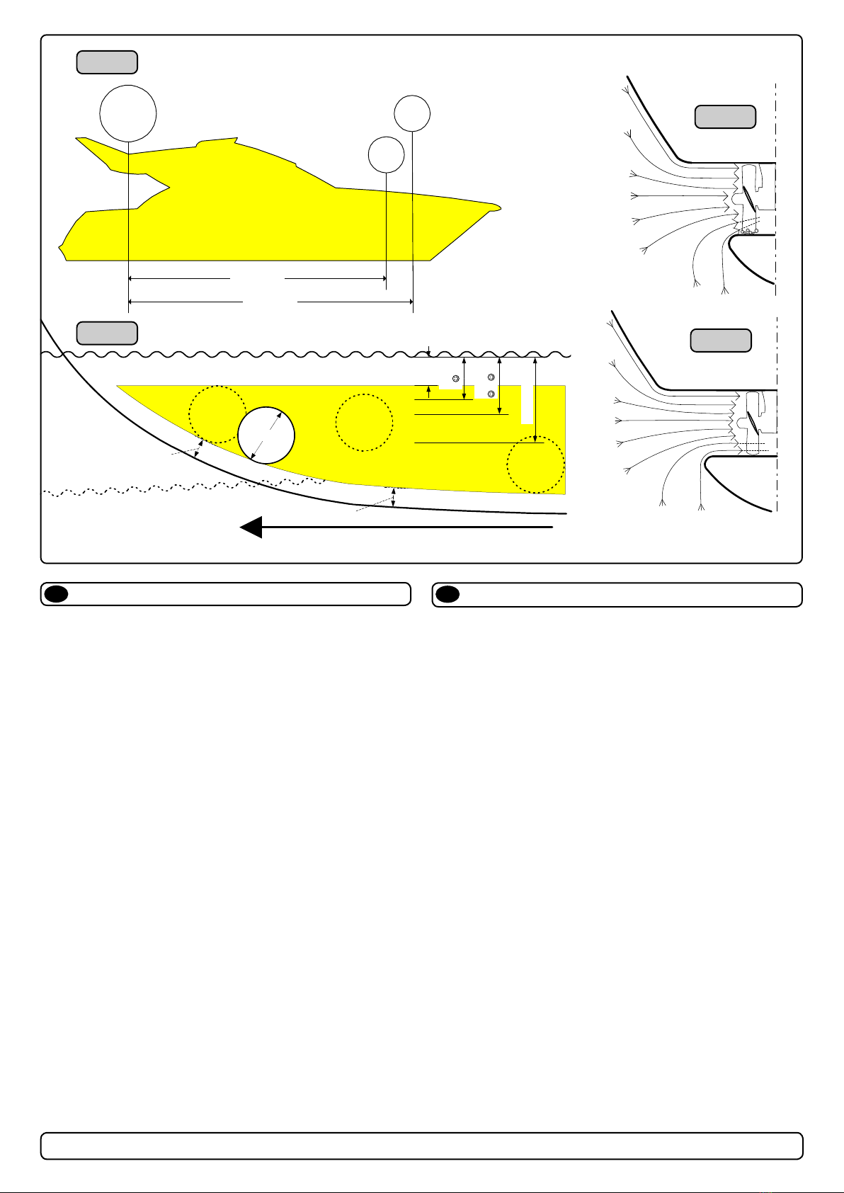
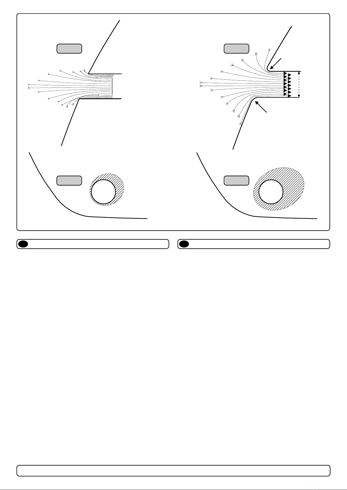
A possible problem in sailboats or fast powerboats, is that they
get a drag from the back face of the tunnel, as this becomes a
“ at” area facing the water ow (Fig. 1).
This can also create problems with the thruster spinning (passive)
and making noise while sailing or driving the boat with water be-
ing pushed through the tunnel at high speed.
This can be solved in two di erent ways, depending on what is
possible or more easy to do.
1. The best solution which normally reduces the drag most, is to
make a recess in the hull at the back of the tunnel.
Thereby the back face is gone and about all the drag (Fig. 2).
The depth and shape of this recess will depend on the boat.
Basically you should not see the back face of the tunnel when
standing directly in front of the tunnel at the angle of the boats
centreline.
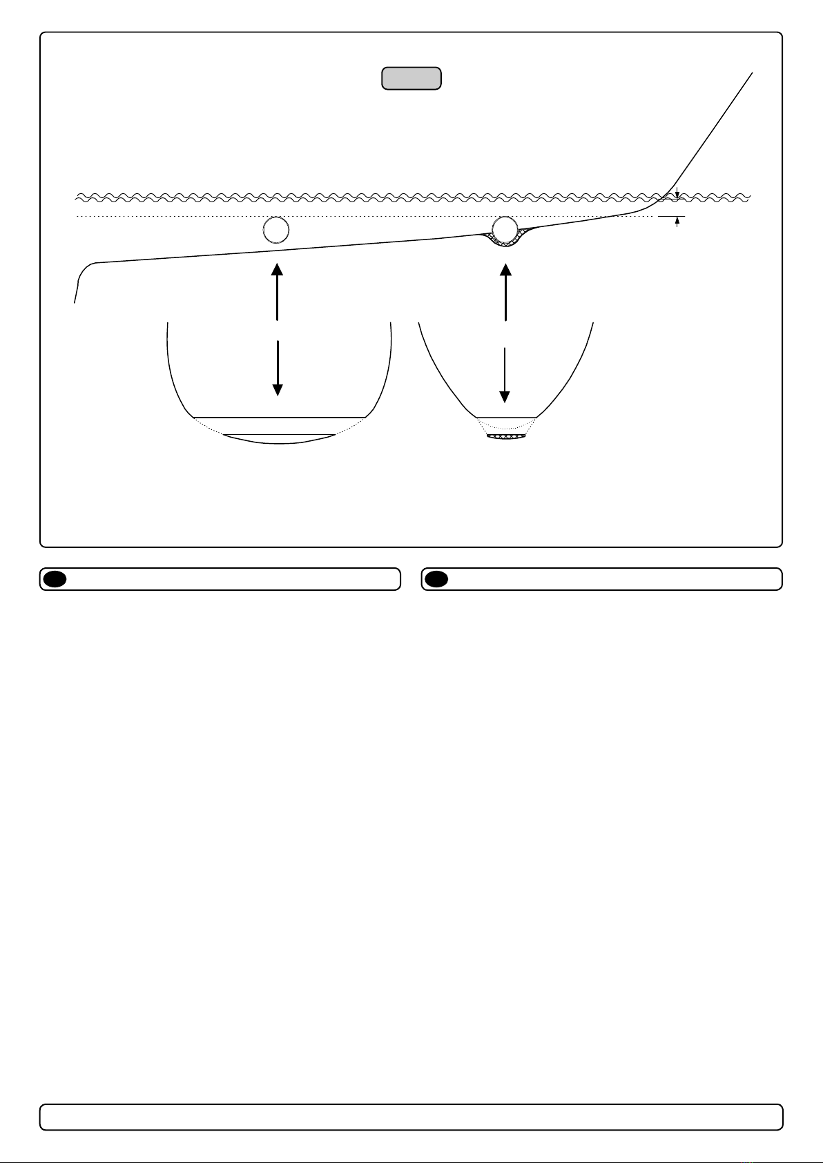
The angle up or down backwards of the insert in the hull, de-
pends on the hullshape, but normally it is angled slightly down
because of the water ow on this area of the hull.
2. The drag will also be reduced a lot, especially in fast power
boats, by making a de ector / spoiler in front of the tunnel.
This will push the water ow out from the hull so that most of it
passes by the back face of the tunnel (Fig. 3).
The shape and size of this de ector will depend on the hull
shape. Basically you should not see the back face of the tunnel
when standing directly in front of the tunnel at the angle of the
boats centreline.
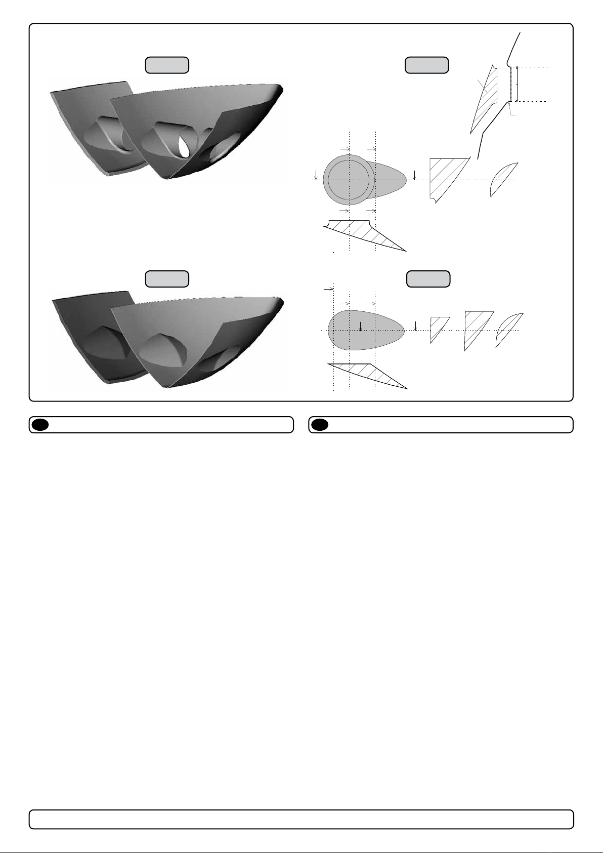
The easiest way of making this is to let a part of the tunnel
stick out in the lower forward area of the hole, and use this as
a support to mould a soft curve / spoiler shape.
Remember to still round the tunnel ends as much as possible to
get optimum thruster performance and minimum noise.
More information on how to practially do this on pages 6.
Prevent drag from tunnel
EN Motstand forårsaket av tunnel
NO
Et mulig problem for seilbåter eller meget hurtiggående båter er
motstand i tunnelen. Aktre ende på tunnelen vil være en liten lod-
drett ate mot vannstrømmen som skaper uønsket motstand.
Denne aten kan også forårsake problemer med at vann føres
inn i tunnelen under seilas, eller kjøring i høy fart og får da propel-
len til å rotere, dette skaper uønsket støy.
Det er to mulige løsninger på problemet, avhengig av hva som er
enklest å få til på båten.
1. Den løsningen som vanligvis reduserer motstanden mest er å
lage en fordypning i skroget i aktre ende av tunnelåpningen.
Den loddrette aten vil da forsvinne og dermed motstanden.
Hovedregelen å følge er at bakkanten av tunnelen ikke skal
synes når man står rett foran båten og titter akterover langs
båten senterlinje. Dybden, utformingen og vinkling av fordyp-
ningen avhenger av båttypen, og hvordan vannet følger skro-
get, men de este båter vil være tjent med en fordypning som
vinkler lett nedover (Fig. 2).
2. Motstanden vil også reduseres av en spoiler i forkant av
tunnelen. Spoileren fører det meste av vannstrømmen rundt
og forbi tunnelen. Størrelsen og utformingen på spoileren
avhenger av båten. Hovedregelen er at bakkanten av tunnelen
ikke skal synes når man står rett foran båten og titter akterover
langs båten senterlinje. Den enkleste måten å lage spoileren
på er å la tunnelen stikke ut i forkant av tunnelen, og forme
spoileren opp mot den (Fig. 3).
Det er alltid viktig å avrunde tunnelåpningene mest mulig for å
motvirke støy og for å få mest mulig eff ekt av thrusteren.
Mer informasjon om dette på side 10.
12
SP 75 Ti / SP 95 Ti / SP 125 Ti
2.5.1- 2007
Formgebung der Tunnelenden
☺☺☺☺☺
�����
Abgerundete Tunnelenden erhöhen die Schubkraft und
reduzieren das Geräuschniveau.
Der Bereich Tunnelende / Außenseite des Rumpfes ist soweit
möglich abzurunden. Der optimale Wert für den Radius dieser
Rundung beträgt 10% des Tunneldurchmessers.
Vorteile gegenüber einer scharfen Tunnel / Rumpfverbindung sind:
1. Abgerundete Tunnelenden verhindern Turbulenzen / Kavitation,
wie sie an scharfenkantigen Tunnelenden auftreten. Damit
werden zwei negative Auswirkungen auf Schubkraft und
Geräuschentwicklung vermieden (Fig. 1 & 2).
- Turbulenz / Kavitation blockieren den äußeren Tunnelbereich.
Dadurch werden effektiver Tunneldurchmesser und Schub-
kraft reduziert.
- Die Turbulenz / Kavitation trifft auf den Propeller und reduziert
dessen Effektivität und führt zu zusätzl. Geräuschentwicklung.
2. Abrundungen ermöglichen, daß Wasser entlang der Rumpf-
außenseite angesaugt werden kann. Dadurch entsteht ein
Vakuum ("zusätzliche" Schubkraft"), das das Schiff seitwärts
bewegt (Fig. 3 & 4). Bei scharfkantigen Enden kann kein
Wasser entlang der Rumpfaußenseite angesaugt werden,
wodurch das benötigte Vakuum nicht zustande kommt.
Diese Schubkraft kann bei optimaler Installation bis zu 30-40%
der absoluten Schubkraft betragen.
NB ! Sidepower Propeller sind so ausgelegt, daß sie nicht
kavitieren, sodaß die Geräuschentwicklung aufgrund von
Kavitation durch die Tunnelinstallation bedingt ist.
NB ! Ist eine optimale Abrundung nicht möglich, so sind die
Tunnelenden soweit möglich abzurunden. Angeschrägte
Tunnel / Rumpfverbindungen sind zu einem gewissen Grad
ebenfalls mit ähnlich positiven Auswirkungen wie eine
Abrundung verbunden (siehe Seite 20, Fig. 1b & 1d).
Tunnel ends
Fig. 2
Fig. 4
Fig. 1
Fig. 3
GB D
R = 0,1 x D (10%)
R = 0,1 x D (10%)
D
Rounded tunnel ends will maximize thrust and minimize
noise.
We recommend rounding the tunnel connection to the hull-side as
much as possible.
The optimum rounding has a radius of 10% of the tunnels diameter.
Important advantages over sharp tunnel to hull connections are:
1. The rounded tunnel end will prevent creation of turbulence
cavitation that will come from a sharp tunnel end when water
passes by fast, thereby preventing a double negative impact on
the thrust and noise level (Fig. 1 & 2).
- The turbulence / cavitation blocks the outer area of the tunnel
and thereby reduces the effective tunnel diameter and thrust.
- The turbulence / cavitation hits the propeller and thereby reduce
the propellers performance and creates noise.
2. The curved tunnel end makes the thruster take water also from
along the hull-side, creating a vacuum that will suck the boat
sideways and thereby give additional thrust (Fig. 3 & 4).
With a sharp tunnel end, the thruster will be unable to take water
from along the hull-side, and you will not get the desired vacuum
and additional thrust. This “free” additional thrust can in optimal
installations be as much as 30 - 40% of the total thrust.
NB! A Sidepower thruster propeller does not cavitate at working
speed so that all cavitation and cavitation noise in the tunnel will
be caused by the tunnel installation.
NB! Even if it is not possible to make the perfect rounding, it is very
important to round the tunnel end as much as possible. A
angled tunnel to hull connection will also do much of the same
job as a rounded connection (see page 20, Fig. 1b & 1d).

8
SE 40/125S2 ignition protected thruster assembly 5456-2 - 2018
Master 4
Tunnel installasjon på seilbåter
N
Mange seilbåtskrog er bygget for å oppnå høy fart. De har brede skrog
som ikke stikker dypt i baugen. Skrogtypen gjør det vanskelig å installere
en thrustertunnel på vanlig måte, spesielt med tanke på å plassere den
langt nok frem (Fig. 1).
Thrustertunneler kan allikevel installeres i de este seilbåter. Dette gjøres
ved å la en del av tunnelen stikke ut i underkant av skroget. Tunnelen er
sterk nok til dette, og thrusteren blir plassert lav nok og langt nok fremme.
Dette gjøres ved at øvre halvdel av tunnelen støpes inn i skroget, tun-
nelen styrkes i underkant ved å støpe en kul rundt tunnelen og jevne den
ut mest mulig.
Denne metoden brukes av noen av de helt største seilbåt-produsentene i
verden, de viser til at den ikke gir utslag på fart under normal seilas.
Denne installasjonen kan også være gunstig for båter med ate bunner,
for å unngå ekstremt lange tunneler og store ovale tunnelåpninger.
Tunnel installation in sailboats
EN
Many sailboats have a racing type hull which means that it is very at bot-
tomed and has a very shallow draft in the bow section. It is thereby very
di cult not to say impossible to t a tunnel thruster the usual way, at least
as far forward in the hull as a thruster should be (Fig. 1).
However, it is possible to install a tunnel thruster in most sailboats, even
when the hull does not directly support the tting of a tunnel.
This is done by tting the tunnel halfway into and halfway under-neath the
existing hull and then strengthen it and smoothening the water ow by
moulding a bulb around / underneath the tunnel.
This will allow installation in good position on the boat, maintaining the
reliability and space advantages of a tunnel thruster.
This installation is being used by some of the world’s largest sailboat
builders, and has been proven to give little to no speed loss for normal
cruising.
This can also be a good installation method for at bottomed barges to
avoid extremely long tunnels and huge oval tunnel openings in the hull.
16
SP 75 Ti / SP 95 Ti / SP 125 Ti
2.5.1- 2007
Segelboote weisen häufig einen Rumpf in Rennform auf, was
einen sehr flachen Rumpf im Bugbereich bedeutet. Es ist daher
schwierig oder fast unmöglich, den Tunnel an der gewünschten
(effektivsten) Stelle, also möglichst weit vorne im Bug zu plazieren
(Fig. 1).
Trotzdem ist es vielfach möglich unter diesen Bedingungen eine
Bugschraube einzubauen, auch wenn der Tunnel damit nicht völlig
vom ursprünglichen Rumpf umgeben ist.
Der Tunnel wird zur Hälfte in den bestehenden Rumpf integriert,
die andere Hälfte geht über diesen hinaus. Der Tunnel muß nur
noch verstärkt und strömungsgünstig abgerundet werden.
Dies erlaubt eine Installation in geeigneter Position bei Nutzung
der Zuverlässigkeits- und Platzvorteile einer Tunnelschraube.
Diese Installationsart wird von einigen der weltweit führenden
Segelboothersteller verwendet und führt meistens nur zu einem
äußerst geringen bzw. gar keinem Geschwindigkeitsverlust.
Diese Bauweise ist auch für Barkassen (z.B. Flußboote) mit
flachem Bug geeignet, um einen zu langen Tunnel und große
ovale Tunnelöffnungen im Rumpf zu vermeiden.
Installation in Segelbooten
D
Tunnel installation in sailboats
Fig. 1
GB
Min
�����☺☺☺☺☺
Pos. B
Pos. A
�����☺☺☺☺☺
Many sailboats have a racing type hull which means that it is very
flat bottomed and has a very shallow draft in the bow section. It is
thereby very difficult not to say impossible to fit a tunnel thruster the
usual way, at least as far forward in the hull as a thruster should be
(Fig. 1).
However, it is possible to install a tunnel thruster in most sailboats,
even when the hull does not directly support the fitting of a tunnel.
This is done by fitting the tunnel halfway into and halfway under-
neath the existing hull and then strengthen it and smoothening the
water flow by moulding a bulb around / underneath the tunnel.
This will allow installation in good position on the boat, maintaining
the reliability and space advantages of a tunnel thruster.
This installation is being used by some of the world’s largest sailboat
builders, and has been proven to give little to no speed loss for
normal cruising.
This can also be a good installation method for flat bottomed barges
to avoid extremely long tunnels and huge oval tunnel openings in the
hull.

9
SE 40/125S2 ignition protected thruster assembly 5456-2 - 2018
Master 5
Some boats is very at bottomed and has a very shallow draft in
the bow section. It might be very di cult not to say impossible to
t a tunnel thruster the usual way, at least as far forward in the
hull as a thruster should be (Fig. 1).
However, it is possible to install a tunnel thruster even when the
hull does not directly support the tting of a tunnel.
This is done by tting the tunnel halfway into and halfway under-
neath the exisiting hull and then strengthen it and smoothening
the water ow by moulding a bulb around / underneath the tunnel.
This will allow installation in good position on the boat, maintaining
the reliability and space advantages of a tunnel thruster.
This can also be a good installation method for at bottomed
barges to avoid extremely long tunnels and huge oval tunnel
openings in the hull.
If the tunnel is over 250 cm long at its deepest point, it is recom-
mend that is is supported by a bulkhead as suggested in g. 2
and 3.
Tunnel installation in fl at bottomed hulls
EN Tunnelinstallasjon i fl atbunnede skrog
NO
Noen båter har brede skrog som ikke stikker dypt i baugen.
Skrogtypen gjør det vanskelig å installere en thrustertunnel på
vanlig måte, spesielt med tanke på å plassere den langt nok frem
(Fig. 1).
Thrustertunneler kan allikevel installeres i de este båter. Dette
gjøres ved å la en del av tunnelen stikke ut i underkant av skro-
get. Tunnelen er sterk nok til dette, og thrusteren blir plassert lav
nok og langt nok fremme.
Dette gjøres ved at øvre halvdel av tunnelen støpes inn i skroget,
tunnelen styrkes i underkant ved å støpe en kul rundt tunnelen og
jevne den ut mest mulig.
Denne installasjonen kan også være gunstig for båter med ate
bunner, for å unngå ekstremt lange tunneler og store ovale tun-
nelåpninger.
Er tunnelen over 250 cm lang, anbefales at den støttes opp av et
skott som vist på g. 2 and 3.
C
D
Fig. 2 Fig. 3
16
SP 75 Ti / SP 95 Ti / SP 125 Ti
2.5.1- 2007
Segelboote weisen häufig einen Rumpf in Rennform auf, was
einen sehr flachen Rumpf im Bugbereich bedeutet. Es ist daher
schwierig oder fast unmöglich, den Tunnel an der gewünschten
(effektivsten) Stelle, also möglichst weit vorne im Bug zu plazieren
(Fig. 1).
Trotzdem ist es vielfach möglich unter diesen Bedingungen eine
Bugschraube einzubauen, auch wenn der Tunnel damit nicht völlig
vom ursprünglichen Rumpf umgeben ist.
Der Tunnel wird zur Hälfte in den bestehenden Rumpf integriert,
die andere Hälfte geht über diesen hinaus. Der Tunnel muß nur
noch verstärkt und strömungsgünstig abgerundet werden.
Dies erlaubt eine Installation in geeigneter Position bei Nutzung
der Zuverlässigkeits- und Platzvorteile einer Tunnelschraube.
Diese Installationsart wird von einigen der weltweit führenden
Segelboothersteller verwendet und führt meistens nur zu einem
äußerst geringen bzw. gar keinem Geschwindigkeitsverlust.
Diese Bauweise ist auch für Barkassen (z.B. Flußboote) mit
flachem Bug geeignet, um einen zu langen Tunnel und große
ovale Tunnelöffnungen im Rumpf zu vermeiden.
Installation in Segelbooten
D
Tunnel installation in sailboats
Fig. 1
GB
Min
�����☺☺☺☺☺
Pos. B
Pos. A
�����☺☺☺☺☺
Many sailboats have a racing type hull which means that it is very
flat bottomed and has a very shallow draft in the bow section. It is
thereby very difficult not to say impossible to fit a tunnel thruster the
usual way, at least as far forward in the hull as a thruster should be
(Fig. 1).
However, it is possible to install a tunnel thruster in most sailboats,
even when the hull does not directly support the fitting of a tunnel.
This is done by fitting the tunnel halfway into and halfway under-
neath the existing hull and then strengthen it and smoothening the
water flow by moulding a bulb around / underneath the tunnel.
This will allow installation in good position on the boat, maintaining
the reliability and space advantages of a tunnel thruster.
This installation is being used by some of the world’s largest sailboat
builders, and has been proven to give little to no speed loss for
normal cruising.
This can also be a good installation method for flat bottomed barges
to avoid extremely long tunnels and huge oval tunnel openings in the
hull.

10
SE 40/125S2 ignition protected thruster assembly 5456-2 - 2018
Master 6
Boat builders having thrusters as standard, or delivering a large
portion of one or more models with thrusters, have the opportu-
nity to make a perfect tunnel installation, while saving both time
and money on each installation (Fig. 1).
The solution is to make an insert / plug in the hull mould, which
prepares the hull for an easy tunnel installation with features for
maximum thrust and minimal drag (Fig. 2).
This insert / plug in the mould is not very di cult to make, and as
it will have to be a "bolt on" in the mould in order to get the boat
out, you can still make boats without this hull feature. (Some boat
builders have this in the hull also on boats that are delivered with-
out a thruster as they know many people will t this later)
By having a at surface to t the tunnel to, the installation time
and cost for the tunnel will also be reduced as:
- it is very easy and fast to cut the now circular hole for the tun-
nel
- it is easier to mould inside all around the tunnel
- you save tunnel length
The plug in the mould can also be made so that it can be a xed
part of the mould, but the rounded end option must then be made
later to get the hull out of the mould (Fig. 3&4).
Series production installation
Fig. 1
Fig. 3
Fig. 2
Fig. 4
EN
a1
b
a1
a2
a2
b
a1 a2
dd
c1
c2 c2 c3
d
b
c3 c1
D
Radius =
D x 0,1
A
a1
b
a1
a2
a2
b
a1 a2
dd
c1
c2 c2 c3
d
b
c3 c1
Båtbyggere som har trustere som standard eller leverer en eller
ere modeller med valgfri truster i stort antall har mulighet for å
lage en perfekt tunnelinstallasjon og samtidig spare tid å penger
(Fig. 1).
Løsningen er å lage en plugg/innsats i formen, som klarrgjør
skroget for anklest mulig tunnelinstallasjon og som samtidig har
perfekt utforming for maksimal trust og minimal motstand (Fig. 2).
Pluggen/innsatsen er ikke komplisert å lage og siden den må
skrus fast i formen på grunn av slipp kan skrogene fremdeles
lages uten denne løsningen. (Enkelte båtbyggere velger også
denne løsningen på båter levert uten truster da de vet at mange
vil velge å ettermontere en truster)
Ved å ha en rett ate å montere tunnelen på, reduseres installas-
jonstiden og kostnaden for tunnelen siden:
- det blir veldig enkelt og raskt å skjære ut det nå sirkulære hullet
til tunnelen
- det er enklere å støpe inn tunnelen langs hele omkretsen
- du sparer lengde på tunnelen
Pluggen i formen kan også lages på en slik måte at den inngår
som en fast del, men da må avrundingen lages etterpå for å
oppnå slipp i formen (Fig. 3&4).
Installasjon ved serieproduksjon
NO

11
SE 40/125S2 ignition protected thruster assembly 5456-2 - 2018
Master 7
We recomend that a professional does the fi breglass fi tting
of the tunnel. These instructions are only general, and do not
explain in any way the details of fi breglass work. Problems
caused by faulty installation of the tunnel, are the installers
full responsibility.
Find the position in the boat considering the information given
earlier in this manual and the applicable measurements for the
thruster model you are installing.
Mark the centre of the tunnel on both sides. Drill a 6mm hole
horizontally in these marks (Fig. 1) .
Bend a ø 5mm steel bar as shown with the "tip" bent back at the
tunnel radius and mark the circle for the tunnel opening (outside
diameter of the tunnel). Cut the hole with a jigsaw (Fig. 2).
Grind o the gelcoat and polyester so that you are down in the
“real breglass” in an area of 12cm around the hole both inside
and outside in the hull to cast the tunnel to the hull (Fig. 3).
Insert the tunnel and mark its shape to t the hull (Fig. 4). If you
are installing with a de ector/spoiler, leave a part or the tunnel of
the front- and underside of the tunnel to have a base for this (see
page 12, Fig. 2). Cut the tunnel ends to the desired shape and
lightly sand its surface and clean with aceton or similar where you
are going to apply breglass.
NB! Do not cast/glass on the area were the thruster will be
placed.
Then cast the tunnel to the inside of the hull, use at least 8 layers
of 300 g glass and resin, preferrably alternating mat and rowing
types of breglass (see page 18, Fig. 1). If you are rounding the
tunnel ends to the perfect 10% radius you may in some cases
have to make further layers inside to preserve the desired hull
thickness.
NB ! Make sure that any gap between the tunell and the hull are
completely lled with resin/ breglass. In areas where you can not
access to make normal layers of resin/ breglass, a resin/ bre-
glass mixture must be lled in that area.
R
D
Tunnel installation
Fig. 1
Fig. 3 Fig. 4
Fig. 2
EN Tunnelinstallering
NO
Sleipner Motor anbefaler at innstøping av glassfi bertunnelen
utføres av kyndig personell. Denne instruksjons manua-
len gir ikke detaljerte opplysninger om glassfi berstøpning.
Problemer som skyldes installering er installatørens fulle
ansvar.
Bestem plassering av tunnelen ut i fra informasjonen gitt tidligere
i manualen, og de angitte mål for thrusteren du skal installere.
Merk av senter på tunnelen på babord og styrbord side. Bor et 6
mm vannrett hull, på begge sider (Fig. 1).
Bøy til og tilpass en 5 mm stålstang, som vist på g. 2 der den
tilbakebøyde enden skal markere tunnelens radius. Stikk enden
inn å marker tunnelens ytre diameter, skjær ut hullet med en
stikksag (Fig. 2).
Puss av gelcoat og polyester så glass beren ligger bar i et 12 cm
stort område rundt tunnel hullet. Dette må gjøres på innsiden og
utsiden av skroget, før tunnelen støpes fast i skroget (Fig. 3).
Sett inn tunnelen å marker hvor det skal kappes for å passe i
skroget (Fig. 4). Hvis det skal støpes en spoiler i forkant av tun-
nelen bør en del av tunnelen stikke ut i for og underkant av skro-
get for å støpe spoileren mot (Side 10, Fig. 2). Kapp tunnelen i
ønsket størrelse. Slip lett med slipepapir, og vask med aceton der
hvor det skal støpes med glass ber.
NB ! Det må ikke støpes der hvor thrusteren skal monteres.
Støp fast tunnelen først på innsiden av skroget, bruk minst 8 lag
med 300 g Glass bermatte, og polyester. Ved bruk av alternative
materialer, glass ber matter eller rovingtyper (Se s. 10, Fig. 1).
Hvis tunnelåpningene avrundes til den optimale 10% radius må
ofte legge ekstra lag med polyester glass bermatte på innersiden
av tunnelen, for å oppnå riktig tykkelse i forhold til skrogtykkelsen.
NB ! Forsikre deg om at overgangene mellom tunel og skrog er
nøye sammenstøpt. På steder en ikke kommer til med vanlige lag
med polyester/glass ber matte, sørg for og lage en blanding av
polyester og glass ber, som fylles i dette.

12
SE 40/125S2 ignition protected thruster assembly 5456-2 - 2018
Master 8
Soften the edges with a radius of 10% of the tunnel diameter
(Fig. 1a) or make a slope with a length of 10 - 15% of the tunnel
diameter (Fig. 1c). If this is not possible, atleast round the tunnel
end as much as possible.
We advice to also cast two layers on the outside of the tunnel/
hull for an area 6-8cm (Fig. 1c&1d).
You must apply gelcoat/topcoat/epoxy on the areas outside where
you have grounded or moulded to again make these waterproof.
NB ! All original Sidepower tunnels are fully waterproof
when they are delivered.
This means that unless you want, because of special reasons, to
have another colour on it, you do not have to apply Gelcoat/Top-
coat or the several layers of primer that is necessary on the boats'
hull to make it waterresistant.
Sand it very lightly and apply one layer of primer to make the
antifouling sit.
The original Sidepower tube itself is fully waterresistant without
treatment exceptin the areas where you have bonded it to the
hull.
Apply gelcoat/topcoat/epoxy paint and primer on the areas where
you have grounded or moulded as these areas give the water
access to the hull which normally is not waterproof without these
applications outside.
PS!
Avoid all casting where the motor-bracket is to be
placed, as this will cause mis t and possible failure
of the gearhouse.
Tunnel installation (Cont.)
EN Tunnelinstallering (Forts.)
NO
Rund av tunnelendene med en radius 10% av tunneldiameter
(Fig. 1a), eller lag en skråkant 10-15% av tunneldiameter (Fig.
1c). Der dette ikke er mulig skal tunnel kantene rundes av mest
mulig.
Vi anbefaler å støpe to lag utenpå tunnelavrundingen og over et
område på 6-8cm (Fig. 1c & 1d).
Gelcoat eller lignende må påføres på områdene der det har blitt
pusset eller støpt for å gjøre glass beren vanntett.
NB ! Alle originale Side-Power tunneler er vanntette ved
levering!
Så fremt man ikke ønsker en annen farge er det ikke nødvendig å
påføre Gelcoat, Topcoat og ere lag med primer for å gjøre tun-
nelen vanntett.
Puss tunnelen med nt slipepapir og påfør et lag primer for å få
bunnsto til å sitte.
Side-Powertunnelen er helt vanntett uten behandling med unntak
av de områder det som er støpt fast i skroget.
Påfør Gelcoat/Topcoat/epoxy og primer på de områder som er
pusset ned eller støpt. Vann skal ikke ha direkte kontakt med
glass beren i skroget fordi dette normalt ikke er vanntett.
PS! Det må ikke støpes der braketten til thrusteren skal stå.
Passformen er nøyaktig tilpasset, og en feilplassert bra-
kett kan forårsake svikt i girhus.
20
SP 30 S2i / SP 40 S2 i/ SP 55 Si
3.5 - 2005
Runden Sie die Kanten mit einem Radius (10% des Tunneldurch-
messers) ab (Fig. 1a) oder machen Sie eine Schräge mit einer
Länge von 10-15% des Tunneldurchmessers (Fig. 1c). Ist beides
nicht möglich, sind die Tunnelenden soweit möglich abzurunden.
Auf der Außenseite zusätzlich zwei Schichten im Bereich Rumpf /
Tunnel auf einer Fläche von 6-8cm auftragen (Fig. 1c & 1d).
Danach auf den äußeren, angeschliffenen oder laminierten Flächen
Gelcoat/Topcoat/Epoxy zur wasserdichten Versiegelung aufbringen.
NB ! Original Sidepower tunnel sind in ausgeliefertem
Zustand absolut wasserdicht.
Wird nicht eine spezielle Farbe gewünscht, so sind keinerlei
Gelcoat, Topcoat oder Primer nötig, die ansonsten zur
Wasserdichtigkeit benötigt werden.
Empfehlenswert ist ein leichtes anschleifen und aufbringen einer
Primerschicht zur besseren Haftung des Antifouling.
Original Sidepowertunnel sind auch ohne Behandlung absolut
wasserdicht.
Auf laminierten oder angeschliffenen Flächen ist Gelcoat / Topcoat /
Epoxy und Primer aufzubringen, da diese Bereiche ohne
entsprechende Behandlung nicht wasserdicht sind.
PS ! Im Bereich der Motorhalterung darf nicht laminiert wer-
den, da dies zu Ungenauigkeiten bei der Montage und
damit einem möglichen Getriebeschaden führen kann.
Tunnelinstallation
D
Soften the edges with a radius of 10% of the tunnel diameter (Fig.
1a) or make a slope with a length of 10-15% of the tunnel diameter
(Fig. 1c). If this is not possible, at least round the tunnel end as
much as possible.
We advice to also cast two layers on the outside of the tunnel/hull for
an area 6-8cm (Fig. 1c & 1d).
You must apply topcoat/epoxy on the areas outside where you have
grounded or moulded to again make these waterproof.
NB! All original Sidepower tunnels are fully waterproof when
they are delivered.
This means that unless you want, because of special reasons, to
have another colour on it, you do not have to apply topcoat or the
several layers of primer that is necessary on the boats’ hull to make
it water resistant.
Sand it very lightly and apply one layer of primer to make the
antifouling sit.
The original Sidepower tube itself is fully water resistant without
treatment except in the areas where you have bonded it to the hull.
Apply topcoat/epoxy paint and primer on the areas where you have
grounded or moulded as these areas give the water access to the
hull which normally is not waterproof without these applications
outside.
PS! Avoid all casting where the motor-bracket is to be
placed, as this will cause misfit and possible failure of
the gearhouse.
Tunnel installation
GB
R = D x 0,1
R = D x 0,1
Dx0,1-0,15
Dx0,1-0,15
D
Fig. 1a
Fig. 1
Fig. 1b
Fig. 2 Fig. 3
Fig. 1d
Fig. 1c

13
SE 40/125S2 ignition protected thruster assembly 5456-2 - 2018
Fig. 1
Bolt on installation of the stern tunnel
1. Make sure that there are enough space both inside and out-
side the transom of the boat.
2. Once the place for the installation has been decided, hold the
tunnel in place in the horizontal position and mark the bolt
holes. Remove the tunnel and it is then possible to calculate
and mark the centre.
3. It is important that the tunnel ange sits ush on the transom.
If this is not so, then the area on the transom will have to be
attened to ensure a snug t.
PS ! Take care with grinders as it is very easy to remove to
much in breglass
At this time, cut out the centre hole and the transom to the
same internal diameter as the tunnel ange and drill the bolt
holes. Before bolting on the stern tunnel, the prepared area
must be sealed with a gelcoat or similar to ensure there is no
water ingress into the hull.
4. Before tting the tunnel to the transom, t the lower gear leg
to the tunnel as described on page 6.
5. When tting the tunnel, ensure that there is ample sealant
(Sikaex or similar) in the sealing tracks of the tunnel ange
and around the bolts to make a water tight tting (Fig. 1/2).
Bolts, washers and nuts are not included as they will wary de-
pending on the transom thickness We recommend A4 stain-
less with A4 lock nuts and A4 washers of a large diameter on
both outside and inside.
Bolts diameter: ø 10mm or 3/8” stainless steel
6. Refer to the installation manual for the recommended thruster
tting.
If a bow thruster is also installed, we strongly advice to
use separate battery banks for the two thrusters to avoid
extreme voltage drop if both thrusters are to be used at the
same time. Refer to the thruster manuals for advised battery
capacity and cable sizes for each thruster.
Also ensure that you do not have direct connections of both +
and - if you have built together controls for both thrusters to
avoid current leakage between separate battery banks.
If you are installing the standard Side-Power dual joystick
panel this is already secured.
Fig. 2
SEALANT
WASHERS
LOCKNUT OR DOU-
BLE NUTS
SEALANT

14
SE 40/125S2 ignition protected thruster assembly 5456-2 - 2018
Fitting gearhouse and motor bracket
EN
Fig.3a
Fig. 4a
1. Mark the centreline of the tunnel and the boats centreline. The gearhouse and propeller must be tted as shown above for the
thrust direction to correspond with the control panel Fig. 1/2.
2. Use the gasket or template(recommended) to mark the centre of the hole and double check the measurements. Note! The
thruster should be placed with the bolt hole as the centre (Fig. 2). All holes must be in-line with the tunnels’ centreline for
precise installation, as the clearance between the propeller and the tunnel is minimal.
3. There must be no casting where the motor bracket is to be placed, as this will cause possible failure of the gearhouse. The motor
bracket must t steady on the tunnel, if the tunnel is not smooth, all bumps or uneven parts must be ground smooth.
4. Drill the main-hole and then the two screw-holes.
5. Try the lower-unit in the tunnel (without the propeller) by using the gasket inside the tunnel. Try on the propeller to en sure it is in
the center of the tunnel and turns freely with the same clearance from each blade to the tunnel. Fig 3a/b.
6. Apply MS Polymer sealant on both sides of the gasket, and then run the gearhouse through the main hole in the tunnel and push
the gearhouse and motor-bracket gently together. Fig 4a/b. See sealant data sheet for correct application process.
7. Screw the lower unit and the motor-bracket together with the two provided bolts. Tighten with 10 Nm / 7,4 lb/ft. Fig 5.
Fig. 1
Fig. 2
Fig. 3b
Fig. 4b
Fig. 5
22
SP 30 S2i / SP 40 S2 i/ SP 55 S2i
3.7 - 2006
1. Die Mittellinie von Tunnel und Boot markieren. Damit Schub-
richtung und Kontrollpanel übereinstimmen, Getriebege-häuse
und Propeller wie oben gezeigt einbauen (Fig.1).
2. Die Löcher mit der Dichtung (A) markieren. Maße überprüfen!
NB ! Der Thruster sollte mit dem Bolzenloch als Zentrum
plaziert werden (Fig. 2&3). Da der Abstand zwischen Propeller
und Tunnel minimal ist, müssen für eine präzise Installation alle
Löcher auf der Mittellinie des Tunnels liegen.
3. Im Bereich der Motorhalterung darf kein Laminat auf dem
Tunnel sein, da dies zu einem Getriebeschaden führen kann.
Liegt die Motorhalterung nicht eben auf dem Tunnel auf, so sind
sämtliche Unebenheiten in diesem Bereich abzuschleifen.
4. Erst das Hauptloch, dann die beiden Bolzenlöcher bohren.
5. Das Getriebegehäuse (ohne Propeller) unter Verwendung der
Dichtung in den Tunnel einpassen. Den Propeller auf die Achse
stecken; dieser muß sich frei bewegen lassen und jedes
Propellerblatt muß den gleichen Abstand zum Tunnel
aufweisen. Ist die Tunnelinnenseite ungleichmäßig, etwas
Sikaflex o.ä. auf-tragen, damit keine undichte Stelle auftritt.
6. Das Getriebegehäuse durch das Hauptloch im Tunnel führen
und vorsichtig mit der Motorhalterung zusammenschieben.
7. Das Getriebegehäuse und die Motorhalterung mit Hilfe der bei-
den Bolzen verschrauben (Anzugsmoment 17 Nm / 12,4 lb/ft).
8. Mit beiliegender Schablone messen, ob die Antriebsachse in
korrekter Höhe zur Motorhalterung steht (Fig. 7).
Bolt tightening forces (2x):
DIN 931 - M 8x55 A2 =
17 Nm (12,4 lb/ft)
Fig. 6
1. Mark the centreline of the tunnel and the boats centreline. The
gearhouse and propeller must be fitted as shown above for the
thrust direction to correspond with the control panel (Fig. 1).
2. Use the gasket (A) to mark the centre of the holes and double
check the measurements. NB! The thruster should be placed
with the bolt hole as the centre (Fig. 2&3). All holes must be in-
line with the tunnels’ centreline for precise installation, as the
clearance between the propeller and the tunnel is minimal.
3. There must be no casting where the motor bracket is to be
placed, as this will cause possible failure of the gearhouse. The
motor bracket must fit steady on the tunnel, if the tunnel is not
smooth, all bumps or uneven parts must be grinded smooth.
4. Drill the main-hole and then the two screw-holes.
5. Try the lower-unit in the tunnel (without the propeller) by using
the gasket inside the tunnel. Try on the propeller to make sure it
is in the middle of the tunnel and turns freely with the same
clearing from each blade to the tunnel. Use sealant e.g. Sikaflex
to ensure that no leakages occur.
6. Push the gearhouse through the main hole in the tunnel and
push the gearhouse and motor-bracket gently together.
7. Screw the lower unit and the motor-bracket together with the
two provided bolts. Tighten with 17 Nm / 12,4 lb/ft.
8. Use the enclosed template to measure that the driveshaft has
come through the motorbracket with the correct height (Fig. 7).
Fig. 1
Fig. 5
A
Fig. 2
SP30S2i
SP40S2i
Fig. 3
SP55S2i
20,5mm
0,81"
Ø 8,5mm
0,33"
TUNNELS
CENTRELINE
BOATS
CENTRELINE
Ø 27,5mm
1,08"
BOW
23,0mm
0,91"
Ø 8,5mm
0,33"
TUNNELS
CENTRELINE
BOATS
CENTRELINE
Ø 28,5mm
1,1"
BOW
Port Starboard
Getriebe und Motorhalterung
D
Fitting gearhouse and motor bracket
GB
Fig. 7

15
SE 40/125S2 ignition protected thruster assembly 5456-2 - 2018
Montering av propell
N
1. Før propellen på akslingen, påse at spline i propellen passer på
spline på aksling. Fig 1.
2. Sett på skiven (2) på propellakselen, deretter strammes låsemut-
teren (1). Fig 2.
NB! Kontroller at propellen roterer fritt.
Fitting propeller
EN
1. Push the propeller on to the shaft and turn until the internal
spline in the propeller hub aligns with the external spline on
the propeller shaft. Fig 1.
2. Place the washer (2) on the propeller shaft and then tighten the
lock-nut (1) on the propeller shaft. Fig 2.
NOTE! Ensure the propeller turns freely.
Fig. 1
Fig. 2

16
SE 40/125S2 ignition protected thruster assembly 5456-2 - 2018
Fig. 2
Fitting the electromotor
EN
1. Insert drive pin on motor shaft, tap the coupling on to the motor shaft. Turn the driveshaft in the gearhouse and the motor shaft so
the track to the motor coupling has a corresponding direction. Fig 1-1b. Use the enclosed template to measure the driveshaft has come through
the motorbracket with the correct height Fig 1c.
2. Slide the motor gently onto the driveshaft and motor bracket. You might have to jiggle it a bit to get it on as the tting is tight. The electromotor can
sit in all directions on the bracket. Ensure the cable terminals are available for electric installation later. Fig2.
3. Fasten the motor loosely to the bracket with the provided bolts.
4. Tighten the bolts holding the motor to the motor bracket with 17Nm /12,4 lb/ft as shown in Fig. 3.
5. Check the drive system by turning the propeller, it will be a little hard to turn (because of the gear reduction and the motor), but you should easily
be able to turn it by hand.
In some cases (shallow installation or workboat/shing boat only) we recommend to protect the propeller by mounting a grid in the tunnel opening. It
is important to keep a grid to a minimum and as streamlined for the thrusters waterow as possible, as it will decrease the eect of the thruster. Do not
circular prole steel as it will decrease thrust signicantly.
Note!
Paint the gearhouse and propeller with antifouling made for propellers. Do not paint the propeller shaft, the anodes or the end face of the gearhouse.
Note!
Do not run the thruster for more than very short bursts without being in the water.
Note!
If the boat is still being built when the electromotor is installed, it must be covered up to avoid dust from the building going into the motor and the sole-
noids. This cover must be removed before the thruster is being used.
Fig. 3
Fig. 1b
Fig. 1c
Fig. 1
BOTTOM
A-A ( 1 : 2 )
B ( 2 : 1 )
A
A
B
1
1
2
2
3
3
4
4
5
5
6
6
7
7
8
8
A A
B B
C C
D D
E E
F F
SM-137058
05-03-2018
A
Designed by Date
1 / 1
Edition Sheet
R. Grindland
Material Type Drawing nr
SM-137058
Copyright All rights reserved
Part nr Size Scale
Title
SE60/185S
Tolerance
NS-ISO 2768-1
SLEIPNER MOTOR AS
A2
4,993 kg 1 : 2
Weight
galvanisk skilt
The coupling is complete with the gear pin to the gearleg.
So, there's only a new pin on the engine.
The tracks on the coupling are 90 degrees above each other. So, it becomes a joint.
This will mean that we are getting rid of clipping and cutting sounds as we are having today, and not eating up the drive pin.
The engine also becomes galvanically separated at the same time.
The coupling is just to tap on the engine axel lightly until it stops.
New enginebracket for SE60, artnr: SM-136297
With reinforced ribs and space for the coupling
New drivepin, artnr: 141285 - pin Ø4 x 32
Coupling, artnr: 140992
Works on: SE50 and SE60
TOP

17
SE 40/125S2 ignition protected thruster assembly 5456-2 - 2018
•Explanation of electrical table
- All cable lengths are the total of + and - (to and from).
- Battery size is stated as minimum cold crank capacity, not Ah.
- Use slow fuse rated to hold stated Amp-Draw for min. 5 minutes.
* Cable size and main battery size when an extra bow battery with minimum the CCA mentioned as A is installed.
•It is important that you use a good cable size and batteries with a high cranking capacity to feed the thruster, because it is the actual
voltage at the motor while running the thruster that decides the output RPM of the motor and thereby the actual thrust. Please see
the list below for advised min. sizes of cables and batteries. You can of course use larger cables for even better results.
•A main switch (*C) that can take the load without noticeable voltage drop must be installed in the main positive lead so the power
for the thruster can be turned o independently of the rest of the system when not on board or in emergencies. This should be placed
in an easily accessible place and the boats instructions should include information that this should be turned o like the other main
switches of the boat.
•We also advice to install a fuse (*D) in the positive lead for protection against short-circuiting of the main cables. This fuse should be
of a adequate quality which normally means that it is physically large as these have less voltage drop than the simple / small ones. It
should be of the slow type and sized to take the amperage draw for at least 5 minutes.
• Remember to use ignition protected fuses and switches if tted in areas that require this feature.
•A circuit breaker can be used instead of the fuse and main power switch as long as the functionality is the same.
• The cable ends must be tted with terminals and these must be well isolated against contact with anything but the proper connection
point.
•If the main switch and fuse are installed in the same gas area they also have to be ignition protected.
• The negative / minus cable connects to the (-) terminal. Bolt M10. Tighten with 20 Nm / 14.75 lb/ft.
• The positive / plus cable connects to the "+" terminal. Bolt M10. Tighten with 20 Nm / 14.75 lb/ft.
Place the included red protection cap rmly on the terminal bolt, as shown in illustration above.
Electrical installation
Battery & cable recommendations:
Minimum and recommended cable dimensions can be identical due to safety margins and cable heat considerations for short cable lenghts.
* Minimum or recommended cable cross section in mm2
NB! Very important to check the following with mainswitch in off position:
After all electrical connections have been completed, check with an ohm meter that there is no electrical connection between electro
motor ange and positive terminal on the motor and between the electro motor ange and the negative (battery -) terminal on the motor.
If you feel unsure on how to perform this check, contact skilled personnel for guidance.
17
SE 30/125S2 ignition protected thruster assembly xxxx-x - 2018
•Explanation of electrical table
- All cable lengths are the total of + and - (to and from).
- Battery size is stated as minimum cold crank capacity, not Ah.
- Use slow fuse rated to hold stated Amp-Draw for min. 5 minutes.
* Cable size and main battery size when an extra bow battery with minimum the CCA mentioned as A is installed.
•It is important that you use a good cable size and batteries with a high cranking capacity to feed the thruster, because it is the actual
voltage at the motor while running the thruster that decides the output RPM of the motor and thereby the actual thrust. Please see
the list below for advised min. sizes of cables and batteries. You can of course use larger cables for even better results.
•A main switch (*C) that can take the load without noticeable voltage drop must be installed in the main positive lead so the power
switches of the boat.
•We also advice to install a fuse (*D) in the positive lead for protection against short-circuiting of the main cables. This fuse should be
of a adequate quality which normally means that it is physically large as these have less voltage drop than the simple / small ones. It
should be of the slow type and sized to take the amperage draw for at least 5 minutes.
•
•A circuit breaker can be used instead of the fuse and main power switch as long as the functionality is the same.
•point.
•If the main switch and fuse are installed in the same gas area they also have to be ignition protected.
•The negative / minus cable connects to the (-) terminal. Bolt M10. Tighten with 20 Nm / 14.75 lb/ft.
•The positive / plus cable connects to the "+" terminal. Bolt M10. Tighten with 20 Nm / 14.75 lb/ft.
Electrical installation
Battery & cable recommendations:
Minimum and recommended cable dimensions can be identical due to safety margins and cable heat considerations for short cable lenghts.
* Minimum or recommended cable cross section in mm2
Bae ry
12Vor
24V
+
Thruster
motor
Thruster
motor
MM
Thruster
motor
M
Tegninger for å illustrere baerikabel -lengder både for std truster og for proporsjonaldriav
truster.
Har benyet *C og *D som dl igere i manualer.Burde kanskje vært forklart at det er summen av
lengden for alle ba.kablene som gjelder for kabeltabellen.
Det bør stå en anbefaling av vår automaske hovedstrømbryter i manualteksten.
Thruster motor
(IP model)
++
*C *D
Bae ry
+
After all electrical connections have been completed, check with an ohm meter that there is no electrical connection between electro
If you feel unsure on how to perform this check, contact skilled personnel for guidance.
RED +
Isolation cap
Red +
Isolation cap
Model Voltage Nominal current
draw
Min. battery
CCA Rec. fuse
<7m total
+ & -
7-14m total
+ & -
15-21m total
+ & -
22-28m total
+ & -
28-35m total
+ & - 36-45m total + & -
Min. Rec. Min. Rec. Min. Rec. Min. Rec. Min. Rec. Min. Rec.
SE40/125S
12 V 315 A
DIN: 300 ANL mm2 35 50 70 95 95 120 120 2x95 2x95 2x120 2x120
260*
SAE: 570 250 AWG 11/0 2/0 3/0 3/0 4/0 4/0 2x 3/0 2x 3/0 2x 4/0 2x 4/0

18
SE 40/125S2 ignition protected thruster assembly 5456-2 - 2018
Control panel installation: See control panel manual
•You can install as many panels as you wish by using optional Y-connectors. If two or more panels are operated at the same time in
opposite directions, the electronic controlbox will stop the thruster until it only receives a signal to go in one direction.
•When using original Side-Power equipment it is all "plug & go".
•If the drive direction of the thruster is the opposite of what expected, the blue and grey wire must be changed on each panel.
•The mechanical installation of the panel is described in the manual following the panel.
•The IP thruster is gas proof based on the control panel lead ending outside of the area that requires ignition protection. The control
adapter lead must be tted in the boat so there is no risk of damage to the insulation, causing explosive gas penetration.
•The thruster control should be placed in a position were it is easy to use, and it is very common to use the thruster at the same time
as your gear / throttle lever so it is normally a user friendly solution to be able to access these with one hand for each control.
Pin conguration of 4 pole AMP contact:
Pin1: BLACK = Ground
Pin2: BLUE = Engages thruster SB solenoid
Pin3: GREY = Engages thruster Port solenoid
Pin4: RED = Positive voltage for control panel
Control panel and control-leads
Connect round end
of control adapter
cable to the round
socket on IP casing
1 2
34
21
34
Pin 4Pin 3Pin 2
Pin 4Pin 3Pin 2
Thr ust er moto r
12 /2 4 V
( IP m o del )
++

19
SE 40/125S2 ignition protected thruster assembly 5456-2 - 2018
IMPORTANT! Very important to check the following with main switch in off position:
After all electrical connections have been completed check with an ohm meter that there is no electrical connection between electro
motor body and positive terminal on the motor and between the electro motor body and the negative (A1) terminal on the motor. If you
feel unsure on how to perform this check, contact skilled personnel for guidance.
"Visual" wiring diagram
EN NVisuelt Koblingsskjema
6 1265 5-LEAD
Y-CONNECTOR
6 1265 5-LEAD
Y-CONNECTOR
6 1278-xxM 5-LEAD
CONTROL CABLE
6 1278-xxM 5-LEAD
CONTROL CABLE
6 1278-xxM 5-LEAD
CONTROL CABLE
6 1277-xxM 4-LEAD
CONTROL CABLE
6 1277-xxM 4-LEAD
CONTROL CABLE
STERN BOW
STERN
BOW
STERN
6 1278-xxM 5-LEAD
CONTROL CABLE
Switch
5A fuse
Switch
5A fuse
Common negative
10A fuse
+
-
+
-
IMPORTANT!
Common negatvie MUST be wired when using control panel 8940 and 8909C
if separate battery banks are installed. (Bow and Stern thtrusters combined)
6 1274 4-LEAD
Y-CONNECTOR
STERN BOW
STERN
BOW
STERN
xA fuse
6 1277-xxM 4-LEAD
CONTROL CABLE
6 1277-xxM 4-LEAD
CONTROL CABLE
6 1277-xxM 4-LEAD
CONTROL CABLE
6 1277-xxM 4-LEAD
CONTROL CABLE
6 1274 4-LEAD
Y-CONNECTOR
xA fuse
Common negative
10A fuse
++
- -
IMPORTANT!
Common negatvie MUST be wired when using control panel 8940 and 8909C
if separate battery banks are installed. (Bow and Stern thtrusters combined)
With Automatic Main Switch:
With Manual Main Switch:

20
SE 40/125S2 ignition protected thruster assembly 5456-2 - 2018
12
SP55S2i ignition protected thruster assembly
1.1 - 2006
SLEIPNER
SIDEPOWER
THRUSTERS
OFF
ON ON
BOW
STERN
To sternthruster
To bowthruster
grey
blue
black
grey
blue
red
ON / OFF
System
Control
light
Joystick
for stern-
thruster
Joystick
for bow-
thruster
Positive lead from
sternthruster have been
removed in panel to
avoid current leakage
between dierent
battery banks if the
thrusters are powered
by dierent battery
banks.
Wiring diagram (simplied) for dual joystick panel
Visual connection diagram for dual joystick panel
We advice to use dierent battery banks for each thruster to ensure
maximum performance when both are used at the same time.
When using the original Sidepower control cables just connect them
to the corresponding joystick
There are no plus/positive power connected from the bowthruster
yellow
BOWSTERN
black
Technical wiring diagram
Electrical installation of stern thruster systems
M
Thermal
switch
Electronic
interface box
6 1232i
A2
A1
4 pin
AMP
connector
On
Motor
4
2
1
3
Fuse Battery
main
switch
1
5
4
2
6
8
9red (+)
grey
(sig +)
blue
(sig +)
black (-)
red
grey
(sig -)
blue
(sig -)
brown
3red
Fused
inside 1A
black
7
white
4
2
1
3
Round
connector
on motor
housing
Table of contents
Popular Safety Equipment manuals by other brands

Clevertronics
Clevertronics L10 Ultrablade Pro LUBPRO-SM Series Installation & maintenance instructions

SCHUBERTH
SCHUBERTH F130 manual

CMC Rescue
CMC Rescue FIRE RESCUE HARNESS manual

EUCHNER
EUCHNER MGB-L1 AR Series operating instructions

Ferno
Ferno 436 Series quick start guide

TOOLCRAFT
TOOLCRAFT 1437615 operating instructions

Kee safety
Kee safety Easi-Dec Valley-Walk Assembly instructions

One Lux
One Lux LED-VERSATILE REMOTE Installation & operating instructions

VIVERSIS
VIVERSIS CARBON operating instructions and important information

Dupont
Dupont Tyvek 500 Xpert blue Instructions for use

ANSI
ANSI PALOMA User instructions

Safety Engineering
Safety Engineering SELF BELAY Operation manual