manuals.online logo
Brands
  1. Home
  2. •
  3. Brands
  4. •
  5. Dräger
  6. •
  7. Safety Equipment
  8. •
  9. Dräger PSS 5000 Series User manual

Dräger PSS 5000 Series User manual

PSS®and Bodyguard®are registered trademarks of Dräger 3358298 (A3-D-P) 1 / 3
3358298
© Dräger Safety UK Limited
Edition 07 – August 2019 (Edition 01 – December 2009)
Subject to alteration
Draeger Safety UK Limited
Ullswater Close Tel +44 1670 352 891
Blyth, NE24 4RG Fax +44 1670 356 266
United Kingdom www.draeger.com
PSS®5000 Series
Self-contained breathing apparatus Instructions for use
i
1 For your safety
1.1 General safety statements
●Before using this product, carefully read the Instructions for Use.
●Strictly follow the Instructions for Use. The user must fully understand
and strictly observe the instructions. Use the product only for the
purposes specified in the Intended Use section of this document.
●Do not dispose of the Instructions for Use. Ensure that they are
retained and appropriately used by the product user.
●Only fully trained and competent users are permitted to use this
product.
●Comply with all local and national rules and regulations associated
with this product.
●Only trained and competent personnel are permitted to inspect, repair
and service the product. Dräger recommends a Dräger service
contract for all maintenance activities and that all repairs are carried
out by Dräger.
●Properly trained service personnel must inspect and service this
product as detailed in the Maintenance section of this document.
●Use only genuine Dräger spare parts and accessories, or the proper
functioning of the product may be impaired.
●Do not use a faulty or incomplete product, and do not modify the
product.
●Notify Dräger in the event of any component fault or failure.
●The air supply shall meet the requirements for breathing air according to
EN12021.
1.2 Definitions of alert icons
Alert icons are used in this document to provide and highlight text that
requires a greater awareness by the user. A definition of the meaning of
each icon is as follows:
WARNING
Indicates a potentially hazardous situation which, if not avoided,
could result in death or serious injury.
CAUTION
Indicates a potentially hazardous situation which, if not avoided,
could result in physical injury or damage to the product or
environment. It may also be used to alert against unsafe practices.
NOTICE
Indicates additional information on how to use the product.
2 Description
2.1 Product overview
The Dräger PSS®5000 Series is a self contained breathing apparatus
(SCBA) that uses an open-circuit breathing system. The series is
compatible with a wide range of compressed-air cylinders, face masks and
lung demand valves (e.g. FPS 7000 and Panorama Nova face masks, PSS
Series lung demand valves, and steel or composite cylinders).
The apparatus can also be fitted with a multi-function electronic monitoring
system (e.g. Bodyguard®7000). Refer to the relevant Instructions for Use
for the description, operation and testing of electronic systems.
2.2 Feature description
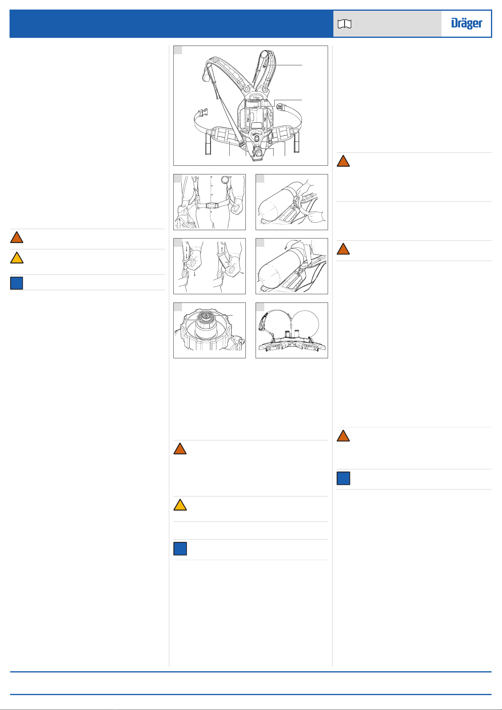
The carrying system has a carbon-composite backplate, with adjustable
shoulder straps and waist belt connected using quick release connectors.
A waist pad (Fig 1, Item 6) connected at a flexible joint compensates for
the twisting and bending of the user. Cylinder mounting systems include a
single cylinder strap (2) or a universal cylinder strap for use with twin
cylinders.
The apparatus uses the Dräger high-performance pressure reducer (4)
that reduces cylinder pressure and supplies breathing air through a
medium-pressure hose (5) and coupling (1) to the attached lung demand
valve. A dual-pressure hose (3) supplies air to the whistle when it is
activated, and has an internal capillary tube that supplies high-pressure air
from the cylinder to the gauge. Air hoses and modular components of the
monitoring system are integrated into the backplate to prevent snagging
and enhance component protection.
Compressed air cylinders, lung demand valves and face masks
The Dräger PSS 5000 Series is compatible with steel or composite
material cylinders of 4 to 9 litre capacities, and 200 or 300 bar pressure.
Full descriptions and user instructions are contained in separate
instructions supplied with the cylinder, mask or lung demand valve.
2.3 Intended use
The Dräger PSS 5000 Series breathing apparatus, when fitted with a
cylinder, lung demand valve and face mask, is intended for use by
emergency services and in industrial applications where a high level of
respiratory protection is required. The assembled breathing apparatus
provides the wearer with respiratory protection for working in contaminated
or oxygen-deficient conditions, and is suitable for fire fighting.
The cylinder, lung demand valve, face mask and other accessories used
with this product must be certified Dräger components, assembled in an
approved configuration. Contact Dräger for further information.
Use in potentially explosive atmospheres
The PSS 5000 Series is type tested as suitable for use in potentially
explosive atmospheres. Electronic sub-assemblies are ATEX certified.
All combinations are suitable for use in hazardous areas up to and
including zone 0 and zone 20.
2.4 Approvals
The European standards, guidelines, and directives according to which
this product is approved are specified in the declaration of conformity (see
declaration of conformity or www.draeger.com/product-certificates).
!
!
i
i
2.5 Explanation of marking and symbols
Refer to the relevant authority for explanation of approval body symbols
and marking on the equipment. Examples of other marking on component
parts of the breathing apparatus are:
BRAC-1359 – Dräger serial number
08/09 – Month and year of manufacture
3356812 or R21034 – Dräger part number
SF – Standard force coupling
LF – Low force coupling
3 Use
WARNING
Only trained and competent personnel may prepare and use
breathing apparatus. Ensure that any accessories, ancillary
equipment and other protective clothing items do not interfere with
the apparatus and do not create a safety hazard.
The effective working duration of the apparatus is dependent on
the initial air supply available and the breathing rate of the wearer.
Fill all air cylinders to their full rated pressure prior to use, and do
not commence any operation using a cylinder that is less than
90 percent full (or greater when national regulations dictate).
CAUTION
Do not apply excessive force or use tools to open or close a
cylinder valve, and do not drop or throw down the breathing
apparatus.
3.1 Preparation for use
NOTICE
The face of the pressure gauge may be fitted with a thin flexible
protective covering. Remove this covering before first use.
1. Carry out a visual inspection of the apparatus (see Section 3.5.1).
2. Fit the air cylinder (see Section 3.5.2).
3. For breathing apparatus with a medium-pressure coupling for the lung
demand valve, disconnect and then reconnect the male coupling. To
connect, press the male coupling into the female coupling until an
audible click is heard. If there is any difficulty disconnecting or
connecting, see the troubleshooting information in Section 4.
4. Press the reset button when using a positive-pressure lung demand
valve (see the Instructions for Use supplied with the lung demand
valve).
5. Carry out a full functional test of the apparatus (see Section 3.5.3).
6. Connect the lung demand valve to the face mask and check the
security of attachment by gently attempting to pull the coupling apart.
3.2 Putting on the breathing apparatus
1. Fully loosen the shoulder straps and waist belt and put on the breathing
apparatus.
!
!
i
i
2. Check that the shoulder pads are not twisted and take the weight of the
system on the shoulders by pulling the shoulder straps. Do not fully
tighten at this stage.
3. Close the waist belt buckle and pull the ends of the waist belt forward
until the strap padding fits securely and comfortably over the hips
(Fig 2). Tuck the belt ends behind the waist pad.
4. Pull the shoulder straps until the breathing apparatus rests securely
and comfortably on the hips. Do not over tighten. Pull the strap
retainers down to secure the strap ends (Fig 3).
5. Fully loosen the head straps of the face mask and place the neck strap
over the back of the neck.
6. Press the reset button when using a positive-pressure lung demand
valve.
7. Open the cylinder valve slowly, but fully, to pressurize the system (if
two cylinders are fitted, fully open both cylinder valves).
8. Put on the face mask and check for tight fit (see the Instructions for Use
supplied with the mask).
3.3 During use
WARNING
Fully open all cylinder valves and ensure that they remain open
during use.
Users should be in a safe area before the whistle warning
commences. Evacuate to a safe area immediately if warnings
commence during an operation.
Using the supplementary air supply will use air from the cylinder
and rapidly reduce the working duration of the apparatus.
●Regularly check the remaining cylinder pressure on the gauge.
●If supplementary air is required, briefly press the rubber cover at the front
of the lung demand valve to deliver extra air into the face mask..
3.4 After use
WARNING
Do not remove the breathing apparatus until in a safe breathing
environment.
1. Loosen the face mask straps. As the seal to the face is broken, press
the reset button when using a positive-pressure lung demand valve.
Remove the face mask.
2. Close the cylinder valve or valves.
3. Press the rubber cover at the front of the lung demand valve to vent
the system fully. Press the reset button when using a positive-pressure
lung demand valve.
4. Release the waist belt buckle.
5. Lift the shoulder strap ends to release the strap retainers (Fig 3) and
then lift the shoulder strap buckles to loosen the straps.
6. Remove the breathing apparatus and face mask.
7. Remove the air cylinder (see Section 3.5.2) if required.
8. Carry out the after use tasks in the maintenance table (see Section 5).
9. Pass the breathing apparatus to the service department with details of
any faults or damage that occurred during use.
3.5 Common user tasks
3.5.1 Visual inspection
A visual inspection must check the full breathing apparatus including all
component parts and accessories. Check that the equipment is clean and
undamaged, paying particular attention to pneumatic components, hoses
and connectors. Typical signs of damage that may affect the operation of
the breathing apparatus include impact, abrasion, cutting, corrosion and
discolouration. Report damage to service personnel and do not use the
apparatus until faults are rectified.
3.5.2 Air cylinder fitting and removing
WARNING
High-pressure air release may cause injury to the user or other
personnel near the breathing apparatus. Close the cylinder valve and
fully vent the system before attempting to disconnect an air cylinder.
Impact damage to the cylinder valve or reducer connector may
prevent valve connection or cause an air leak. Handle the air
cylinder and breathing apparatus with care.
NOTICE
For other cylinder connector types, refer to the Instructions for Use
supplied for the connector.
Fitting a single cylinder with a threaded connector
1. Check the threads of the cylinder valve port and the pressure reducer.
Ensure that the O-ring seal (Fig 4, Item 1) and the sintered filter (2) in
the reducer are clean and undamaged.
2. Lay the backplate horizontal, with the reducer uppermost, and fully
extend the cylinder strap.
3. Insert the cylinder through the loop of the strap, and align the valve with
the reducer.
4. Lift the cylinder and backplate into the vertical position (supported on
the end of the cylinder opposite the valve).
5. Tighten the hand wheel of the reducer, using only the thumb and index
finger, until a definite metal-to-metal contact is felt. Do not use tools or
over tighten.
6. Place the unit back into the horizontal position.
7. Take up the slack in the cylinder strap (Fig 5).
8. Pull the strap over the cylinder to operate the cam lock (Fig 6) and
secure using the hook-and-loop fastening.
Removing a single cylinder with a threaded connector
1. Close the cylinder valve and fully vent the system.
2. Lay the backplate horizontal, with the cylinder uppermost.
3. Remove the free end of the cylinder strap from the hook-and-loop
fastening.
4. Lift the strap against the cam lock to release the buckle tension and
loosen the strap.
5. Disconnect the cylinder valve from the pressure reducer.
6. Lift the cylinder away from the reducer and remove the cylinder.
!
!
!
i
i
2
346 5
1
1
3086
'
3087
2
'
3094
5
3088
3
3095
6
12
3104
4
3107
7
Dow Corning®and Molykote®are registered trademarks of Dow Corning Corporation 3358298 (A3-D-P) 2 / 3
PSS®5000 Series
Self-contained breathing apparatus Instructions for use
i
Fitting twin cylinders with a threaded connector
1. Check the threads of the cylinder valve ports, T-piece and the pressure
reducer. Ensure that the O-ring seal and the sintered filter in the
reducer are clean and undamaged (Fig 4).
2. Connect the T-piece to the pressure reducer, but do not fully tighten.
3. Lay the backplate horizontal, with the pressure reducer uppermost,
and fully extend the cylinder strap ensuring that the strap loops are
approximately equal (Fig 7).
4. Insert the cylinders through the loops of the strap and align the valves
with the T-piece. Connect each valve to the T-piece, but do not fully
tighten.
5. Align the cylinders in the centre of the backplate. Tighten the hand
wheels of the T-piece and reducer, using only the thumb and index
finger, until a definite metal-to-metal contact is felt. Do not use tools or
over tighten.
6. Take up the slack of the cylinder strap (Fig 5), ensuring that both
cylinders are securely held.
7. Pull the strap over the cylinder to operate the cam lock (Fig 6) and
secure using the hook-and-loop fastening.
Removing twin cylinders with a threaded connector
1. Close the cylinder valves and fully vent the system.
2. Lay the backplate horizontal with the cylinders uppermost.
3. Remove the free end of the cylinder strap from the hook-and-loop
fastening.
4. Lift the strap against the cam lock to release the buckle tension and
loosen the strap.
5. Disconnect the T-piece from the pressure reducer and cylinders.
6. Lift the cylinders away from the reducer and remove the cylinders.
3.5.3 Functional testing
WARNING
Failure of the breathing apparatus to meet any of the standards or
parameters described in the functional tests indicates a system
fault. Report the fault to trained service personnel or contact
Dräger. Do not use the breathing apparatus until the fault condition
is rectified.
Assemble the breathing apparatus as described in the preparation for use
(see Section 3.1) before commencing any functional testing.
Leak test and whistle warning test
1. Press the reset button when using a positive-pressure lung demand
valve.
2. Slowly and fully open the cylinder valve (anticlockwise). During
pressurization, a momentary sounding of the whistle will occur.
3. Fully close the cylinder valve.
4. After one minute, check the contents gauge and then reopen the
cylinder valve. The gauge must not show an increase in pressure of
more than 10 bar (one radial marking on the gauge face). Investigate
and repair a failed leak test (see Section 4), and then repeat the leak
test.
5. Fully close the cylinder valve.
6. Observe the contents gauge and slowly release the pressure as
follows:
a. Positive-pressure lung demand valves – Cover the outlet port of
the valve with the palm of the hand. Press the rubber cover to
switch on the positive pressure. Vent the system by carefully lifting
the palm of the hand from the outlet port to maintain a slow
pressure decrease.
b. Negative-pressure lung demand valves – Slowly vent system by
carefully pressing the rubber cover.
7. The whistle must begin to sound in the range 60 bar to 50 bar.
8. Continue to vent the system until fully exhausted.
9. Press the reset button when using a positive-pressure lung demand
valve.
4 Troubleshooting
The troubleshooting guide shows fault diagnosis and repair information
applicable to breathing apparatus users. Further troubleshooting and
repair information is available in Instructions for Use supplied with
associated equipment.
Where the troubleshooting guide shows more than one fault or remedy,
carry out repair actions in the order that they appear in the table.
Contact service personnel or Dräger when the remedy information
indicates a service task, or if the symptom remains after all remedy actions
have been attempted.
5 Maintenance
5.1 Maintenance table
Service and test the breathing apparatus, including out-of-use apparatus,
in accordance with the maintenance table. Record all service details and
testing. Refer also to the Instructions for Use for the lung demand valve,
face mask and other associated equipment.
Symptom Fault Remedy
High-pressure air leak or
failed leak test
Loose or dirty connector Disconnect, clean and
reconnect couplings and
retest
Faulty hose or
component
Substitute user
replaceable accessories
and retest
Air leak from medium-
pressure hose connection
at the pressure reducer
(safety relief valve)
Faulty O-ring, retainer,
spring or pressure
reducer
Service task
High or low medium
pressure
Pressure reducer fault Service task
Poor sounding whistle Whistle dirty Clean whistle flute and
retest
Whistle not functioning
correctly
Activation mechanism
fault
Service task
Difficulty connecting or
disconnecting the
medium-pressure quick
coupling
Dirty connector Disconnect, clean and
reconnect couplings and
retest
Burring of the male
coupling
Replace the hose with the
male coupling
!
Additional inspection and testing may be required in the country of use to ensure compliance with national regulations.
5.2 Cleaning and disinfecting
CAUTION
Do not exceed 60 °C for drying, and remove components from the drying facility immediately when dry. Drying time in a heated dryer must not
exceed 30 minutes.
Do not immerse pneumatic or electronic components in cleaning solutions or water.
If water is trapped and then freezes inside the pneumatic system of the breathing apparatus (such as the lung demand valve), operation will be
impaired. Prevent any liquid from entering, and thoroughly dry the breathing apparatus after cleaning to prevent this from occurring.
For information about suitable cleaning and disinfecting agents and their specifications refer to document 9100081 on www.draeger.com/IFU.
Refer also to the Instructions for Use for the lung demand valve, face mask and other associated equipment.
●Use only clean lint-free cloths
1. Clean the breathing apparatus manually using a cloth moistened with cleaning solution to remove excess dirt.
2. Apply disinfecting solution to all internal and external surfaces.
3. Rinse all components thoroughly with clean water to remove all cleaning and disinfecting agents.
4. Dry all components using a dry cloth, in a heated dryer or in air.
5. Contact service personnel or Dräger if disassembly of pneumatic or electronic components is required
5.2.1 Carrying harness – Thorough cleaning
CAUTION
Thorough cleaning may only be carried out by suitably trained personnel. Disassembly of the breathing apparatus by untrained personnel is not
permitted and may damage the apparatus.
1. Remove the harness from the carrying system and clean using one of the following methods:
a. Clean manually in a bath containing recommended cleaning or disinfecting agents.
b. Machine wash (at 30 °C) using a suitable cleaning agent.
2. Rinse the harness thoroughly with clean water to remove all cleaning and disinfecting agents.
3. Dry all components including internal parts.
5.3 Maintenance work
5.3.1 Repositioning the pressure gauge or medium-pressure coupling
The pressure gauge and medium-pressure coupling (and other shoulder mounted accessories) can be repositioned in line with user preferences.
Components can be placed on the same side or swapped to opposite sides by trained service personnel. Instructions for repositioning shoulder mounted
components are contained in the technical manual.
5.3.2 Air cylinder charging
WARNING
The air supply shall meet the requirements for breathable air according to EN12021.
Refer to the instructions supplied with the cylinder and the charging apparatus for recharging a compressed air cylinder.
6 Storage
6.1 Storage preparation
●Extend the shoulder straps, waist belt and the straps of the face mask.
●For storage, place the face mask in a protective bag (contact Dräger for supply of a suitable bag).
●Route rubber hoses in such a way that the bend radius is not too acute and the hose is not stretched, compressed or twisted.
6.2 Storage conditions
●Store the equipment between -15 °C and +25 °C. Ensure that the environment is dry, free from dust and dirt, and does not subject the equipment to
wear or damage due to abrasion. Do not store the equipment in direct sunlight.
●Fix the breathing apparatus securely to any raised mounting point to prevent it from falling.
Component/
System Task Before
use
After
use
Every
month
Every
year
Every 6
years
Every 10
years
Complete
apparatus
Visual inspection (see Note 1 and Section 3.5.1)
Notes
O Dräger recommendations
1. Clean the equipment if it is dirty. If it the equipment has been exposed to contaminants, disinfect any components that come into direct and prolonged
contact with the skin.
OOO
Functional testing (see Section 3.5.3) O O O
Breathing cycle and static tests (see Note 2)
2. These maintenance tasks may only be carried out by Dräger or trained service personnel. Details of the tests are contained in the Technical Manual
which is issued to service personnel that have attended a relevant Dräger maintenance course.
O
Lung demand
valve
Check push-in type connectors for lubricant (see Note 3)
3. For type A check the O-ring on the lung demand valve; and for type ESA check the outer surface of the male part of the push-in connector on the
lung demand valve. As a guide, lubricant should be felt on the fingers but not seen. If relubrication is required, lightly apply Dow Corning®
Molykote®111 (other lubricants are not tested and may damage the equipment).
O
Check the male element of the quick coupling for burring (see Step 3 in Section 3.1) O
Overhaul. Contact Dräger for the Repair Exchange (REX) service (see Note 4)
4. Overhaul every 6 years is applied to equipment users subject to German regulations only. Users in Germany must meet the requirements of: German
fire brigade regulations (FwDV 7 and vfdb – RL0804), and German national regulations (BGR 190 or GUV R190 and GUV-I-8674).
O
Pressure
reducer
Medium-pressure check (see Note 2) O
Inspect the sintered filter (see Note 2 and Note 5)
5. Replace the sintered filter if a drop in reducer performance is observed during a flow check or if it is visibly damaged.
O
Inspect the high-pressure connector O-ring (see Note 2 and Note 6)
6. Replace the high-pressure connector O-ring if it is found to leak during functional testing or if the O-ring is visibly damaged.
O
Overhaul. Contact Dräger for the Repair Exchange (REX) service
(see Note 4 and Note 7)
7. Where the breathing apparatus is subjected to a high level of use (in training establishments etc.), reduce the overhaul period for the pressure reducer.
In these circumstances, Dräger recommend that the overhaul frequency should be less than 5,000 applications of use. An application of use is defined
as a single use of the fully assembled breathing apparatus, where the user breathes from the air cylinder. It does not include system pressurization
for pre-operational checks.
OO
Cylinder Charge cylinder to correct working pressure O O
Check charged pressure (stored cylinders only) O
Check test date of cylinder O
Recertification According to national regulations in the country of use
Cylinder valve Overhaul At the time of cylinder recertification
!
!
!!
3358298 (A3-D-P) 3 / 3
PSS®5000 Series
Self-contained breathing apparatus Instructions for use
i
7 Technical data
High-pressure connection Standard G5/8” as per EN 144-2
(200 bar or 300 bar)
Compressed air cylinders 4 litre to 9 litre (200 bar or 300 bar),
steel or composite materials
Whistle warning Initial activation: 60 bar to 50 bar
Medium pressure 6 bar to 9 bar
Operating temperature EN137 temperature range
8 Order list
Description Quantity Order code
Dow Corning®Molykote®111 100 grams 3331247

Other Dräger Safety Equipment manuals

Dräger X-plore 6000 User manual

Dräger

Dräger X-plore 6000 User manual

Dräger PAS AirPack User manual

Dräger

Dräger PAS AirPack User manual

Dräger SPC 4900 User manual

Dräger

Dräger SPC 4900 User manual

Dräger CDR 4500 User manual

Dräger

Dräger CDR 4500 User manual

Dräger saver PP Series User manual

Dräger

Dräger saver PP Series User manual

Dräger PSS 7000 Series User manual

Dräger

Dräger PSS 7000 Series User manual

Dräger PSS 4000 Series User manual

Dräger

Dräger PSS 4000 Series User manual

Dräger FPS 7000 RP User manual

Dräger

Dräger FPS 7000 RP User manual

Dräger SPC 4800 User manual

Dräger

Dräger SPC 4800 User manual

Dräger HPS SafeGuard User manual

Dräger

Dräger HPS SafeGuard User manual

Dräger PSS 3000 Series User manual

Dräger

Dräger PSS 3000 Series User manual

Dräger Panorama Nova RA User manual

Dräger

Dräger Panorama Nova RA User manual

Dräger SPC 2400 Flexothane User manual

Dräger

Dräger SPC 2400 Flexothane User manual

Dräger UCF 6000 User manual

Dräger

Dräger UCF 6000 User manual

Dräger BG ProAir User manual

Dräger

Dräger BG ProAir User manual

Dräger Oxyboks KT User manual

Dräger

Dräger Oxyboks KT User manual

Dräger Oxy K 30 S User manual

Dräger

Dräger Oxy K 30 S User manual

Dräger Saver CF User manual

Dräger

Dräger Saver CF User manual

Dräger X-plore 8000 User manual

Dräger

Dräger X-plore 8000 User manual

Dräger Oxy 3000 MK II User manual

Dräger

Dräger Oxy 3000 MK II User manual

Dräger X-plore 2100 User manual

Dräger

Dräger X-plore 2100 User manual

Dräger VarioGard User manual

Dräger

Dräger VarioGard User manual

Dräger Bodyguard 1000 User manual

Dräger

Dräger Bodyguard 1000 User manual

Dräger X-plore 8000 User manual

Dräger

Dräger X-plore 8000 User manual

Popular Safety Equipment manuals by other brands

Yale TIGRIP SHARK-S operating instructions

Yale

Yale TIGRIP SHARK-S operating instructions

Gin Safari Passenger user manual

Gin

Gin Safari Passenger user manual

Datalogic SAFEasy SE4-PLUS Series instruction manual

Datalogic

Datalogic SAFEasy SE4-PLUS Series instruction manual

Petzl DELTA TECHNICAL NOTICE

Petzl

Petzl DELTA TECHNICAL NOTICE

MSA Advantage 4000 Series Maintenance and Repair

MSA

MSA Advantage 4000 Series Maintenance and Repair

Horizon Signal SQ3TS user manual

Horizon Signal

Horizon Signal SQ3TS user manual

Petzl QUICKFIX C09100 manual

Petzl

Petzl QUICKFIX C09100 manual

Mustang Survival MD3003 owner's manual

Mustang Survival

Mustang Survival MD3003 owner's manual

SafeWaze FS-FSP1215-G instruction manual

SafeWaze

SafeWaze FS-FSP1215-G instruction manual

e-breathe Multimask M instruction manual

e-breathe

e-breathe Multimask M instruction manual

Reely LiPo Safety Bag operating instructions

Reely

Reely LiPo Safety Bag operating instructions

Squire SNAPLOK Fitting instructions

Squire

Squire SNAPLOK Fitting instructions

EUCHNER 156622 manual

EUCHNER

EUCHNER 156622 manual

Climbing Technology SPARROW 200R manual

Climbing Technology

Climbing Technology SPARROW 200R manual

EDELRID CLIP SAVER manual

EDELRID

EDELRID CLIP SAVER manual

Bornack LORY STOP user manual

Bornack

Bornack LORY STOP user manual

Aervoe 1154 operating instructions

Aervoe

Aervoe 1154 operating instructions

KStrong Kapture Element Hotworx User instruction manual

KStrong

KStrong Kapture Element Hotworx User instruction manual

manuals.online logo
manuals.online logoBrands
  • About & Mission
  • Contact us
  • Privacy Policy
  • Terms and Conditions

Copyright 2025 Manuals.Online. All Rights Reserved.