Siebring HEATWAVE HW150 User manual

WARM IT UP WITH AFREE SOURCE OF HEAT!
Siebring Manufacturing, Inc.
303 S. Main St. PO Box 658
George, IA. 51237
Ph. 712-475-3317
Fax 712-475-3490
www.siebringmfg.com
5-1-23

SECTION 1 - WARRANTY
1.1 KAGI WARRANTY. Kagi Heating Supplies & Manufacturing, Inc. (KHS) will warranty
parts and labor to the consumer for a period of twelve months from the date of purchase. KHS
warranties each burner sold will be free of defects in materials and workmanship under
normal use and service for a period of one year. Date of purchase will be date received by the
customer. See Kagi Burner manual for detailed warranty information.
1.2 HEATWAVE WARRANTY. HEATWAVE Warrants to the purchaser of this Multi-Oil Fueled
Heater Unit that it will repair or replace any part which in normal use proves to be defective in
material or workmanship within a period of ONE (1) YEAR from the date of purchase, provided
same is returned for factory inspection and warranty determination. The combustion chamber
(Limited Warranty) is warranted for a period of TEN (10) YEARS at a pro-rated schedule,
provided the heater is properly installed and maintained.
HEATWAVE does not warrant the paint finish as this is subject to abrasion, scratching, and
discoloration during installation and operation. The warranty does NOT cover any labor
charges involved with parts replacement or service unless preauthorized by Siebring Mfg., Inc.
in writing.
1.3 CONDITIONS THAT WILL VOID WARRANTY.
Using in the heater or adding to the storage tank substances, including, but not limited to the
following: paint, thinner, gasoline, other volatile liquids, or solvents, transformer oils, or gear
lubes. Some of these substances have a high chloride content which can oxidize HEATWAVE
stainless steel targets and chambers. It is illegal to mix any of these substances with waste oil
and doing so can cause a hazardous condition.
Tampering with internal components.
Not installing the heater properly as per instruction in this manual and/or according to local and
state codes.
Not maintaining the heater according to instructions in this manual or by authorized personnel.
Any part altered or abused.
Using parts other than those supplied by Siebring Mfg., Inc. to operate this heater
Over-firing the unit.
Warranty is limited to the original purchaser only, and is void if moved form original site of
installation.

SECTION 2 –GENERAL INFORMATION & HAZARDS
2.1 INTRODUCTION. The Heatwave heater by Siebring Mfg. provides the owner with a
dependable, versatile and simple means of burning # 1 and # 2 fuel oils, 10W –50W used
crank case oils and used automatic transmission fluid. Maintained correctly, the heater will
give years of service. Carefully read the owner’s manual before installing and using the unit.
In the event there is a problem with your heater or the installation of your heater, contact your
distributor for assistance.
2.2 DIMENSIONS. Dimensions are calculated without the burner.
Heatwave 150 65” x 35” x 39”H Crated weight 700 lbs. (see figure 1)
Heatwave 250 75” x 36” x 49”H Crated weight 840 lbs. (see figure 2)
Heatwave 350 60” x 36” x 82”H Crated weight 1080 lbs. (see figure 3)
2.3 FIRING CAPACITIES.
Heatwave 150 1.1 –1.5 gallons per hour.
Heatwave 250 1.7 –2.0 gallons per hour.
Heatwave 350 2.5 –3.2 gallons per hour.
2.4 NON-RESIDENTIAL WARNING. This heater is for commercial and industrial use only.
This unit is NOT rated for residential use.
2.5 ADHERANCE TO CODES. Installation of this unit is to be done in accordance with all
state and local codes or authorized having jurisdiction over environmental control, fuel, fire and
electrical safety.
2.6 APPLICABLE CODES FOR HEATER INSTALLATION. National Fire Protection
Association (N.F.P.A.) codes for heater install.
NFPA 30 Flammable and Combustion Liquids Code
NFPA 31 Standards for the Installation of Oil-Burning Equipment Code
NFPA 70 National Electrical Code
NFPA 88A Standard for Parking Structures Code
NFPA 88B Standard for Repair Garages Code
NFPA 211 Standard for Chimneys, Fireplaces, Vents, and Solid Fuel-BurningAppliances
The above codes available from the National Fire Protection Association,
1 Batterymarch Park, Quincy, MA. USA 02169-7471 Tel. 617 770-3000 www.nfpa.org
2.7 INSTALLATION. This heater and systems must be installed by an experienced, qualified
waste oil fired heater installer.
2.8 DUCTWORK. This heater is not designed for attachment or use with ductwork.

2.9 WARNING. Do not attempt to start the burner when excess oil, oil vapor or fumes have
accumulated. To prevent backfire that could harm personnel or possibly damage the unit,
NEVER press the reset on the primary control more than two times.
2.10 WARNING. Do not store gasoline or any other flammable liquids, or vapor producing
materials near the heater.
2.11 WARNING. This heater is not designed for use in hazardous atmospheres such as:
paint shops, feed mills, or any installations where explosive or flammable conditions are
present or could occur.
2.12 WARNING. Heatwave heaters by Siebring Mfg. rely on a natural gravity draft. Down
drafts (positive) pressures in the heater’s chimney will occur in buildings where negative
pressures are created by exhaust fans (car exhaust vents, spray booths, ventilation fans, etc.),
Do not try to use a power vent to overcome a downdraft pressure. An adequate air make-up
system is needed when exhaust fans are used.
SECTION 3 –HEATER INSTALLATION
3.1 Do not install heater on a combustible material of any kind.
3.2 Install heater in a location to utilize total heat throw.
3.3 Install heater in a location to permit a correct outdoor chimney exit to eliminate down
drafts, provide easy chimney installation and maintenance.
3.4 Install the heater in a location to permit as close as possible fuel supply.
3.5 Do not install heater more than 10 feet above top of fuel tank (see page ?? Learn about
special pump installations).
3.6 Before suspending the heater, check the supporting structure and reinforce if necessary
to support the heater/system. See figure 4 for unit weights.
3.7 Minimum clearances to combustibles:
Top 6” Chimneys 18”
Sides 18” Rear 18”
Front 24” Bottom 18”

3.8 Use threaded rod rated for applicable heater weight to suspend from a capable load
carrying ceiling structure.
3.9 Heater should be installed level for proper operation. Heater installed “not level” could
cause a hazardous situation in which personal injury or property damage could result.
3.10 When installing the heater, keep in mind that you must have reasonable access to the
unit for servicing.
3.11 Installation Diagram Page:
1. Chimney Cap 11. Electrical Service panel
2. Class “A” insulated pipe 12.Air Compressor (2.4 CFM+)
3. Barometric Damper 13. Pump with vacuum gauge
4. Capped Chimney “Tee” 14. Fill Pipe
5. Draft Reading Port 15. Water/sludge Drain
6. Oil Regulator (on burner) 16. Lenz Oil Filter
7. SecondaryAir Regulator 17. Vent Pipe
8. Burner 18. Check Valve
9. Room Thermostat 19. Oil Pick-up Strainer
10. Primary Air Regulator 20. Supply Tank
Notes:
-Do Not use compression fittings or unions on the suction side. Use flare fittings and threaded
fittings with thread compound.
-Do Not use Teflon tape.
-Do Not use air lines that have an automatic oiler.
-If shop air is 125 PSI or lower, the primary air regulator (item 10) is not required. If shop air is
125 PSI or greater, install primary air regulator and adjust air to 125 PSI or below.
-A moisture/water trap must be installed in the air line prior to the burner.
-Some state/local codes may require the supply tank to be vented outside (item 17).

4.1 Failure to provide proper venting of the heater exhaust gases could result in death, serious injury
and/or property damage.
4.2 Safe operation of any gravity vented heating equipment requires a proper air make-up system to
prevent heater exhaust gases from being drawn into the building which may cause death, serious
injury and/or property damage.
4.3 Never vent this heater into another heater’s chimney. This heater must have it’s own separate
chimney.
4.4 Inspect and maintain the chimney and air make-up system regularly.
4.5 Install a U.L. listed barometric draft control in chimney. Do not reduce or enlarge the vent pipe.
4.6 To prevent drawing exhaust gases into the building, keep barometric draft control at least two feet
form the heater, exhaust fans, etc.
4.7 Position draft control as shown in pages ??, gate hinge pins must be horizontal for proper
operation.
4.8 Secure all chimney/piping connections with 3 screws/rivets per joint.
4.9 Chimney clearance to combustibles –18 inches.
4.10 Do not install heat reclaimers, manual draft controls or any other type of restrictive controls in
the chimney.
4.11 Install an 8” diameter steel vent “tee” with a cap (for clean out) at the transition of the chimney.
4.12 Use 8” inside diameter class A insulated chimney pipe to vent exhaust gases through walls,
ceilings, attics, roofs, combustibles, etc. Consult state and local codes.
4.13 Vent chimney at least 3 feet above the roof and at least 3 feet higher than any portion of the
building, roof or obstruction within 10 feet of the chimney.
4.14 Do not use a rotating chimney cap. Use a non-restrictive cap.
4.15 Chimney caps should be at least 4 inches above chimney exit.
4.16 The chimney must be capable of producing a negative -.02 - .04 W.C. draft when hot as measured
between the heater and the draft control. Refer to section 5 “Draft.” Refer to section 3 for typical
chimney installation.
SECTION 4 –CHIMNEY INSTALLATION

SECTION 5 –DRAFT
SECTION 6 –FUEL SUPPLY TANK INSTALLATION
5. The chimney system connected to the Heatwave should have a negative -.02 - .04 W.C. draft
when hot (minimum of 10 minute run time) as measured between the heater and the draft control.
6.1 The fuel supply tank and supply line must be installed in accordance with the National Fire Protection
Association requirements, state and local codes and ordinances.
6.2 Regulations require oil storage tanks located inside the building not to exceed 275 gallons individually
and not to exceed 550 gallons in one building.
6.3 Locate fuel tank inside the building as close to the heater as possible. Not to exceed 25 feet to avoid oil
flow problems.
6.4 If possible, pitch/position fuel tank with the drain valve at the lowest point to drain off water. Sludge
may have to be removed manually.
6.5 Some areas may have special requirements for the fuel tank vent (exiting outdoors, above the roof line,
etc,) check local codes and ordinances. Keep vent clear.

Dimensional view of HW 150 (measurements) Figure 1
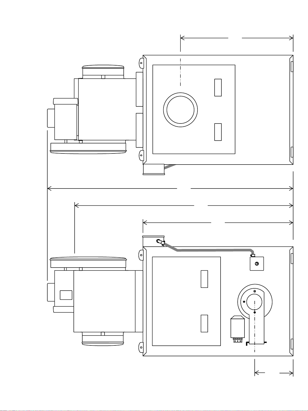
Dimensional view of HW 250 (measurements) Figure 2
Dimensional view of HW 350 (measurements) Figure 3
Dimensional view of HW 350 (continued) Figure 4
HeatWave Specifications Figure 5
Kagi Burner Drawing Figure 6
Furnace Installation Example Figure 7
Multi-Wall Chimney Installation Figure 8
Furnace Installation Example Drawing Figure 9
Floating Oil Pick-up (dirty tanks) Figure 10
Oil Primary Control Figure 11
Nozzle Exploded View Figure 12
ElectrodeAdjustment Figure 13
Air Regulator Exploded View Figure 14
Oil Regulator Exploded View Figure 15
Flame Characteristics Figure 16
Exploded view Air / Oil Solenoid Figure 17
Delta Pump Figure 18
Suntec J Pump Figure 19
Suntec 7740 Figure 20
Webster M17DN Pump Figure 21
Webster 1RR14 Figure 22
Pump / Motor Alignment Figure 23
Lenz Filter System Figure 24
Fan Belt Adjustment Figure 25
Breaker box Figure 26
Wiring Schematic Figure 27
Burner Wiring Diagram Figure 28
Wiring Burner Cord & Junction Box Figure 29
Honeywell Fan & Limit Control Figure 30
White-Rodgers Fan & Limit Control Figure 31
Terminal Strip Wiring Figure 32
Kagi Wiring - Drawing A Figure 33
Kagi Wiring - Drawing B Figure 34
Kagi Wiring - Drawing C Figure 35
Kagi Wiring - Drawing D Figure 36
Kagi Wiring - Drawing E Figure 37
Kagi Wiring - Drawing F Figure 38
Kagi Wiring - Drawing F (ICM) Figure 39
Kagi Wiring - Drawing F-1 Figure 40
Kagi Wiring - Drawing F-2 Figure 41
Air and Oil Pre-heaters Figure 42
Parts HW150/250 Figure 43
Parts HW350 Figure 44
HW Cleaning Figure 45
HW Cleaning(continued) Figure 46
Warning / Caution Decals Figure 47
Warning / Caution Decals (continued) Figure 48
Warning / Caution Decals (continued) Figure 49
INDEX OF DRAWINGS

Figure 1
150
45”
65”
28.5”39”
13”
11”
35”
Top View
Left Side ViewLouver End View
Right Side View
Heatwave150 –150,000 BTU
Crated = 69”L x 42”W x 45”H
Shipping weight = 700 lbs.
HW150
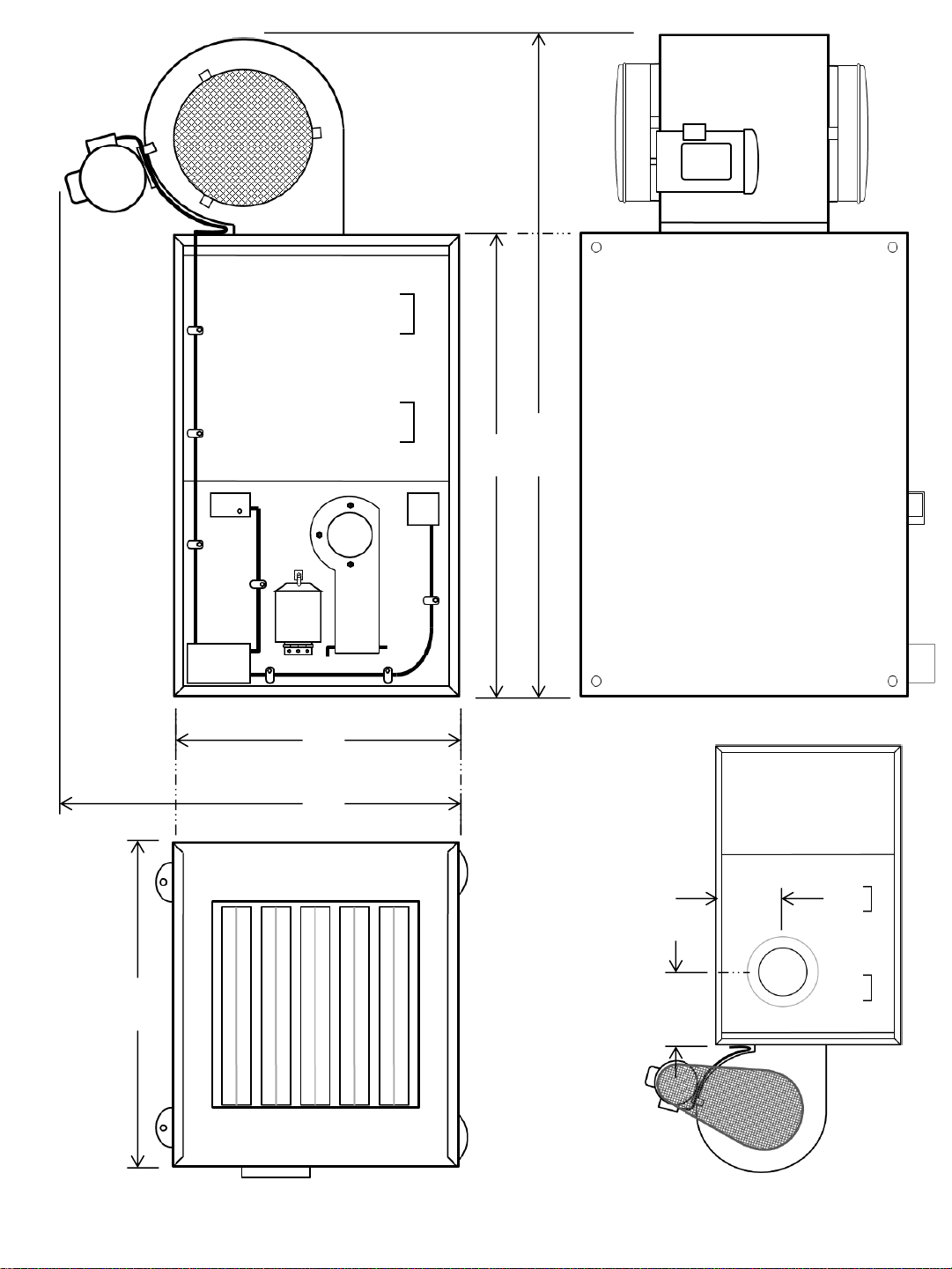
Figure 2
45”
Left Side View
Louver End View
33”
52”
74 ½”
Top View
11 ½”
13”
Right Side View
Heatwave250 –250,000 BTU
Crated = 80”L x 44”W x 50”H
Shipping weight = 800 lbs.
HW250
36”

Figure 3
350
Heatwave350 –350,000 BTU
Crated = 68”L x 45”W x 85”H
Shipping weight = 1080 lbs.
80”
60”
36”60”
Right Side View Top View
4 – 12” Ø Vents
HW350
12” Ø
48”
70.5”
80”
38”
13.5”
Heatwave350 –continued
8” Ø
Chimney
Chimney End ViewBurner End View
HW350
Figure 4

SIEBRING MANUFACTURING - HEATWAVE SPECIFICATIONS
28-Apr-09 D. Hollander
Model HW150 HW250 HW350
BTU Input 150,000 BTU 250,000 BTU 350,000-380,00 BTU max
Square Foot Coverage Up to 4,500 sq. ft.* Up to 6,000 sq. ft.* Up to 8,000 sq. ft.*
Hourly Fuel Usage 1.1 - 1.5 gallons 1.7 - 2.0 gallons 2.5 - 3.1 gallons
Compressed Air Requirements 2 CFM** 2.5 CFM** 3 CFM**
PSI Air 15 20 25
Flue Size 8 inches 8 inches 8 inches
Cabinet Size (w/o burner) 35" W x 45" L x 29" H 36" W x 52" L x 34" H 36" W x 60" L x 48" H
Width Overall (w/blower &
burner) 48 inches 48 inches 36 inches
Length Overall (w/blower &
burner) 65 inches 75 inches 70 inches
Height Overall (w/blower &
burner) 40 inches 49 inches 82 inches
Crated Dimensions 42" W x 69" L x 45" H 44" W x 80" L x 50" H 45" W x 70" L x 84" H
Ductable Heat Discharge Yes Yes 4 12" Elbows
Air Movement Type Belt Driven Blower Belt Driven Blower Belt Driven Blower
Blower CFM Free Air 3140 3950 4800
Blower Motor HP 3/4 HP 3/4 HP 2 HP
Plenum Dimensions 18 X 23 23 x 23 4 -12" or 22" X 22"+
Hanging Mount 5/8 " All Thread 5/8 " All Thread Floor / Stand
Mounting Design (Floor or tank
stand) Floor, ceiling hung or tank
stand Floor, ceiling hung or tank
stand Floor / Stand
Stand Mount / Oil Tank Yes Yes No
Electrical Voltage 115 Volt 60 Hz 115 Volt 60 Hz 115 Volt 60 Hz
Average Total Amperage Draw 12 - 13*** 15 - 16*** 19 - 20***
Weight (with blower & burner) 520 lbs. 700 900
Approximate Shipping Weight 700 lbs. 840 1,040
Warranty 1 yr burner, blower, controls.
10 yrs. Cabinet 1 yr burner, blower, controls.
10 yrs. Cabinet 1 yr burner, blower,
controls. 10 yrs. Cabinet
* Depending on building insulation, ** Owner must supply compressed air, *** Total Amps = Burner, blower and oil pump
Construction (All Models): 10 GA - Combustion chamber barrel, swing-out bracket 11 GA - Exchanger tube bulkheads
12GA 309 SS - Target
12 GA - Burner mount tube, cleanout doors 14 GA - Shell (case) bottom, pot tubes 16 GA - Shell (case) top 18 GA - Shell
(case) sides
Figure 5

PREHEATER ON
PUMP ON
OFF
KAGI
WASTE OIL BURNER
TECHNOLOGY
PUMP ON
OFF
ONOIL TEMP
LENZ
CARLIN
IGNITOR
(41000SOAR)
Air Pressure
12 PSI Minimum
SOFT START
AIR TANK
OIL
CONNECTION
OIL
REGULATOR
OIL
PRESSURE
AIR REGULATOR
AIR PRESSURE
AIR
SOLENOID
AIR CONNECTION
BLOWER
MOTOR
KAGI S250/500
WASTE OIL BURNER HINGED
COVER
HINGE
POWER
CORD
Figure 6
AIR
ADJUSTMENT
BAND
PREHEATER
SWITCH

20. Supply
Tank
19. Strainer
18. Check Valve
16. Filter 13. Pump w/vac gauge
15. Water/sludge
drain
14. Fill pipe
17. Vent pipe to
outside
4. Capped Tee for easy
chimney cleaning
1. Rain or Sail Cap
Avoid screen in cap Clearance 18+ inches
Chimney connector, ¼” rise per ft.
3. Barometric Dampner, 2 –3’ away
from forced air fan or drafts
Securely hang heater using ⅝” all-thread
9. Low voltage (24V)
room thermostat
11. Electrical Service &
disconnect panel:
-20 Amp service for
150,000 & 250,000 BTU
-30 Amp service for
350,000 BTU
Clearance to walls –refer
to local codes
5. Draft reading port
2. Class “A” chimney (insulated
pipe) See local codes
150,000/250,000 BTU Heater Installation Example
Note: Use flare fittings and threaded
fittings with thread compound.
Do not use compression fittings.
Do not use Teflon tape.
Barrier to protect from traffic damage
6. Oil Regulator (on burner)
7. Secondary Air Regulator (on burner)
8. Burner
10. Primary Air
Regulator
12. Compressor
Figure 7

18” min.
18” min.
to wall
RAIN CAP
STORM COLLAR
ADJ. ROOF
FLASHING
FIRE STOP
SPACER
WALL BAND
WALL RADIATION
SHIELD
WALL SUPPORT
FINISHING
ADAPTER
WALL ADAPTER
INSULATED TEE
2” min.
12” LENGTH
STOVE PIPE
INSTALL WALL SUPPORT TO LEAVE 2”
GAP BETWEEN INSULATED TEE & WALL
* Check footnote for
chimney clearances
Avoid screen in chimney cap.
Vent chimney at least 3 feet above the roof
and at least 3 feet higher than any portion
of the building, roof or obstruction within 10
feet of the chimney. The max height of the
assembly above the roof shall not exceed
6 feet. If the total length of the insulated
chimney exceeds 30 feet, install additional
supporting assemblies supplied by the
chimney manufacturers. Never locate a
joint inside walls or in a joist spacer.
*
JOIST
JOIST
STORM COLLAR
ADJ. ROOF
FLASHING
JOIST SPACER
I.C. PIPE LENGTHS
(INSULATED CHIMNEY)
N.B. CHIMNEY MUST BE
INSTALLED WITH AIR GAP AS
STATED ON EACH SECTION.
CEILING
SUPPORT
BLACK STOVE PIPE
MULTIPLE WALL INSULATED CHIMNEY INSTALLATION
Figure 8

FLOOR
ROOF
Oil Tank
5’ MIN.
36”
MIN.
18” MIN.
18” MIN.
30”
Floor clearance as required
by state/local code
RemovableTee
cap for cleaning
Removable Tee
cap for cleaning
Barometric
damper
Barometric
damper
Blower
Class “A” insulated pipe, may be
higher than drawing if more draft
is required
22 GA, MIN.
Rule of Thumb:
Estimate 2 feet of vertical
chimney for every 1 foot of
horizontal pipe.
Figure 9

Thin wall, gasoline proof,
flexible rubber hose
Thin wall, gasoline proof,
flexible rubber hose
Float
Float
Check valve
Check valve
Strainer
Strainer
Oil Tank
Oil Tank
Flow to
pump
Flow to
pump
Restrict hose length so
strainer cannot reach
the sludge on the
bottom of the tank.
FLOATING PICKUP SUMP FOR DIRTY STORAGE TANKS
Sludge level
Sludge level
Tank
Cross
View
Tank
Cross
View
Vent to
outside
Vent to
outside
Fill Pipe
Fill Pipe
10” min. to
avoid sludge
10” min. to
avoid sludge
Straight
through
gate valve
Figure 10

Oil Primary Control
F2
F1
T2
T1
F2
F1
T2
T1
F2
F1
T2
T1
Yellow wires to cad cell
The primary control provides 24
volt thermostat connections.
Use # 18-2 wire (Bell wire).
At unit start-up, a jumper wire can
temporarily be installed to by-pass cad
cell to allow for priming of oil lines and
pump. Additionally, jumper can be
reinstalled to check for cad cell
malfunction.
Note: Do not connect jumper up first as
burner will not start. Start burner
without jumper wire, then connect
jumper across F1 & F2 terminals to
keep burner and pump operating.
WARNING! Do not operate burner
continuously or unattended with jumper
connected. The safety shutdown will
be disabled in this configuration. Install
for troubleshooting only.
1500 ohm ½ watt resister to
check control cad cell circuitry.
Carlin Primary Control
Figure 11
RESET
Carlin Primary Control
Carlin Primary Control
RESET
RESET

HEATWAVE NOZZLE –TYPICAL (HAGO)
HEAD DISTRIBUTOR STEM O-RING
HEAD DISTRIBUTOR STEM O-RING
HEATWAVE NOZZLE –TYPICAL (DELAVAN)
SN
609-7
30609
- 7
Normal application: HW150 = 609-5, HW250 = 609-7, HW350 = 609-9
Figure 12
O-Ring - 007 = 5/32 I.D. x 9/32 O.D. x 1/16
O-Ring - 007 = 5/32 I.D. x 9/32 O.D. x 1/16
This manual suits for next models
2
Table of contents


