Siegen tools S775G User manual
INSTRUCTION MANUAL
SPRAY GUN GRAvitY feed
1.3mm Set-UP
MODEL NUMBER
S775G
Thank you for purchasing a Siegen Tools product. Manufactured to a high standard this product will, if used according to these instructions
and properly maintained, give you years of trouble free performance.
IMPORTANT: PLEASE READ THESE INSTRUCTIONS CAREFULLY. NOTE THE SAFE OPERATIONAL REQUIREMENTS, WARNINGS AND CAUTIONS. USE THIS
PRODUCT CORRECTLY AND WITH CARE FOR THE PURPOSE FOR WHICH IT IS INTENDED. FAILURE TO DO SO MAY CAUSE DAMAGE AND/OR PERSONAL INJURY
AND WILL INVALIDATE THE WARRANTY. PLEASE KEEP INSTRUCTIONS SAFE FOR FUTURE USE.
1. SAFETY INSTRUCTIONS
Familiarise yourself with the application, limitations and potential hazards peculiar to the spray gun.
WARNING!Disconnect the spray gun from the air supply before changing accessories, servicing or performing any maintenance.
Ensure spray gun is well maintained and kept in good condition (use an authorised service agent).
Replace or repair damaged parts. Use recommended parts only. Unauthorised parts may be dangerous and will invalidate the warranty.
Keep the spray gun thoroughly clean for best and safest performance.
Ensure that the compressed air system can supply the spray gun air consumption (12 to 15cfm).
Wear approved safety respiratory protection and safety eye goggles.
If spraying isocynate based finisher, wear approved respirator/clean air breathing apparatus and cover exposed skin with latex gloves and an
impervious hooded coverall.
Remove ill-fitting clothing. Remove ties, watches, rings and other loose jewellery and tie back long hair.
Locate the spray gun in a suitable work area. Keep area clean and tidy and free from unrelated materials and ensure that there is adequate
ventilation and lighting.
Keep children and unauthorised persons away from the work area.
When not in use, ensure that the air supply is turned off.
Avoid unintentional operation of spray gun.
DO NOT point spray gun at yourself, other persons or animals.
DO NOT direct air from the air hose at yourself, other persons or animals.
DO NOT carry the spray gun by the hose, or pull the hose from the air supply.
DO NOT exceed the maximum air pressure of 70psi.
DO NOT use the spray gun for any purpose other than that for which it is designed.
DO NOT allow untrained persons to operate the spray gun.
DO NOT get the spray gun wet or use in damp or wet locations or in areas where there is condensation.
DO NOT operate the spray gun if any parts are missing or damaged, as this may cause failure and/or personal injury.
When not in use, disconnect the spray gun from the air supply, clean thoroughly before storing in a safe, dry, childproof location.
2. SPECIFICATION
S775G Spray Gun Gravity Feed 1.3mm Set-Up
Standard set-up:......................1.3mm
Available set-ups: ..S775G.SET1.5 - 1.5mm set-up
. . . . . . . . . . . . . . . . S775G.SET1.8 - 1.8mm set-up
. . . . . . . . . . . . . . . . S775G.SET2.0 - 2.0mm set-up
Working pressure range: ..............30-70psi
Air consumption:....................12-15cfm
Pot capacity:..........................600ml
Original Language Version S775G Issue: 1 - 21/06/10
Professional gravity fed spray gun, ideal for automotive renishing.
2-Stage trigger control. Adjustable spray width and uid ow. Suitable
for use with water based paints. Maintenance tools supplied. Alternative
set-ups available separately.
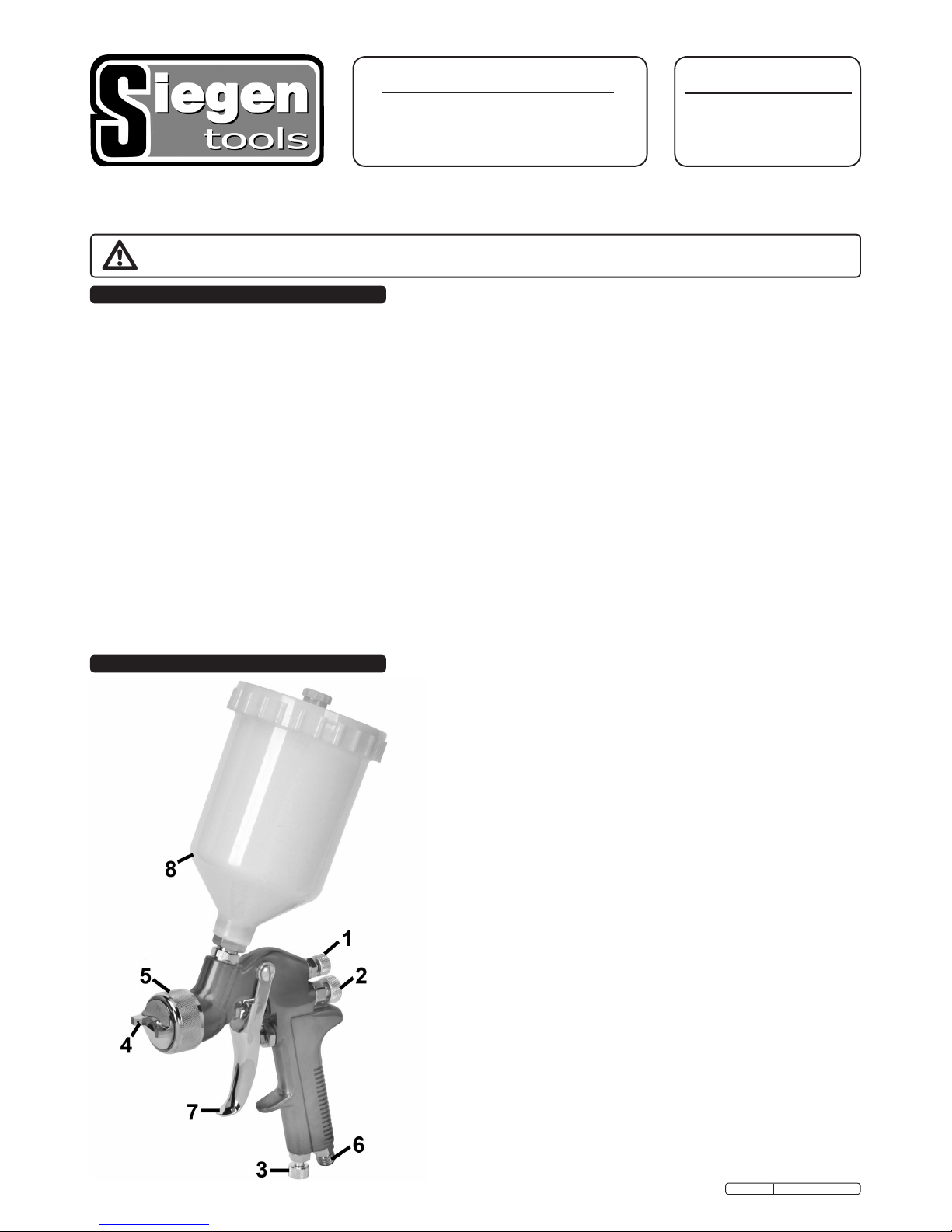
Features:
1 Spray Width Adjuster
2 Fluid Needle Adjuster
3 Air Adjuster
4 Nozzle
5 Nozzle Retainer
6 Air Inlet
7 Trigger
8 Fluid Pot
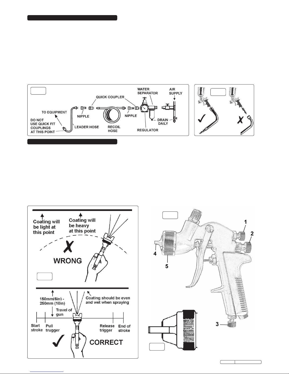
fig.1 fig.2
3.1. Recommended hook-up procedure is shown in fig.1.
3.1.1. Ensure spray gun air valve (or trigger) is in the off position before connecting to the air supply.
3.1.2. The spray gun requires an air pressure of at least 30psi, and an air flow according to specification.
3.1.3. WARNING! Ensure the air supply is clean and does not exceed 70psi whilst operating the spray gun. Too high an air pressure
and/or unclean air will shorten the product life due to excessive wear, and may be dangerous causing damage and/or personal injury.
3.1.4. Drain the air tank daily. Water in the air line will ruin the paint finish and damage the spray gun.
3.1.5. Clean air inlet filter weekly.
3.1.6. Line pressure should be increased to compensate for unusually long air hoses (over 8 metres). The minimum hose diameter should
be ¼” I.D. and fittings must have the same inside dimensions.
3.1.7. Keep hose away from heat, oil and sharp edges. Check hose for wear, and make certain that all connections are secure.
3.2. Couplings
Vibration may cause failure if a quick change coupling is connected directly to the spray gun. To overcome this, connect a leader hose
to the spray gun. A quick change coupling may then be used to connect the leader hose to the air line recoil hose. See figs.1 and 2.
4.1. For best results, the gun should be held perpendicular to the surface being sprayed, and moved parallel to it. Start the stroke before
squeezing the trigger and release the trigger before finishing the stroke. This will enable accurate control of the gun and material (fig.3).
4.2. Spray from a distance of about 150 to 250mm (6 to 10 inches) depending on the material and the atomising pressure. The material
deposited should always be even and wet. Each stroke must overlap the preceding stroke to obtain a uniform finish. To reduce
over-spray and obtain maximum efficiency, spray with the lowest possible atomising air pressure.
4.3. Controlling the fan spray and the fluid.
a) Use the needle (paint) adjuster (fig 4.2) to increase or decrease the amount of paint flow.
b) The atomising air flow is controlled by the spray width adjuster (fig.4.1). The volume of air input is controlled by the air adjuster (fig.4.3).
c) As width of spray is increased more material must pass through the gun to obtain the same coverage on the increased area.
d) Turn the nozzle (fig4.4) to achieve a horizontal or vertical fan spray. Lock the nozzle with the retaining ring (fig.4.5).
The spray pattern of the gun is variable from round to flat with all patterns in between. In normal operation, the wings on the
nozzle are horizontal as in fig.5. This provides a vertical fan-shaped pattern which gives maximum uniform, even coverage when
moving the gun back and forth, parallel to the work surface.
3. AIR SUPPLY
4. OPERATING INSTRUCTIONS
fig.5
fig.4
fig.3
Original Language Version S775G Issue: 1 - 21/06/10

FOR OPTIMUM PERFORMANCE IT IS VERY IMPORTANT TO ENSURE THE GUN IS CORRECTLY CLEANED AFTER EACH USE.
Disconnect from the air supply before attempting any cleaning or maintenance.
5.1. Cleaning the gun
5.1.1. Immerse the front end of the gun only in solvent. The solvent should just cover the
fluid connection (fig.7).
5.1.2. Use a bristle brush and solvent to wash off accumulated paint.
5.1.3. Do not immerse the entire gun in solvent as this will cause lubricants on the rubber
seals to dissolve. Dirty solvent may also clog narrow passages in the gun.
5.1.4. Flush the gun through with clean solvent.
5.1.5. Wipe the outside of the gun with a dampened solvent rag.
5.2. Air nozzle, fluid nozzle and needle assembly
5.2.1. To clean the nozzles, soak them in solvent to dissolve any dried material then blow them
clean with air. Handle all nozzles carefully and do not make any alterations in the gun.
5.2.2. If you need to probe the holes in the nozzles, be sure to use a tool that is softer than
brass; do not use metal instruments.
5.2.3. Adjust the fluid needle valve so that when the gun is triggered, air flow occurs before fluid flow.
5.3. Maintenance
Take care when re-assembling. Screw parts hand tight to avoid cross-threading. If a part cannot easily be turned by hand, check that
you have the correct part, or unscrew, realign and try again. DO NOT use excessive force when re-assembling.
5.3.1. Lubricate the gun daily, use a light machine oil on the fluid needle packing, air valve packing, side port control packing and trigger
pivot point.
5.3.2. If the nozzle size is changed, ensure the complete nozzle set is exchanged. Insert paint nozzle before putting the paint needle in.
6.1. A faulty spray is usually caused by improper cleaning or dried material around the fluid nozzle tip or in the air nozzle. Soak these parts in a
solvent that will soften the dried material and remove with a brush or a cloth. Never use metal instruments to clean the air or fluid nozzles.
These parts are carefully machined and any damage to them will cause a faulty spray. If either the air nozzle or fluid nozzle is damaged,
the part must be replaced before a perfect spray can be obtained.
Dried material in a dirty side port restricts passage of
air. Greater flow of air from the cleaner side port forces
a fan pattern in the direction of the clogged side.
Dried material around the outside of the fluid nozzle tip
restricts the passage of atomizing air at one point
through the centre opening of the air nozzle and results
in the pattern shown. This pattern can also be caused
by a loose air nozzle.
1) Material too thin/ too wide a spray.
2) Atomisation air pressure too high.
Spitting due to:
1) Dried out packing around needle valve.
2) Dirt between the fluid nozzle seat and body or
loosely installed fluid nozzle.
3) Loose or defective swivel nut on syphon cup or
material hose.
Dissolve material in the side ports with solvent, then blow the gun
clean. Do not poke into the opening with metal instruments.
Remove the air nozzle and wipe off fluid tip using a rag dampened
with solvent. Tighten the air nozzle.
1) Increase material control & adjust spray width to narrow..
2) Reduce air pressure.
1) Use a light machine oil on the needle valve packing.
2) Remove the fluid nozzle, clean the back of the nozzle and the
nozzle seat in the gun body using a rag dampened with thinner.
Replace the nozzle and secure it tightly against the body.
3) Tighten or replace defective swivel nut.
VIEW OF PROBLEM POSSIBLE REASON FOR PROBLEM SOLUTION
5. CLEANING & MAINTENANCE
6. TROUBLESHOOTING
Keep solvent level
below packing
fig.7
Sole UK Distributor: The Siegen Tool Co., Bury St. Edmunds, Suffolk IP32 7AR E-mail: [email protected]
NOTE: It is our policy to continually improve products and as such we reserve the right to alter data, specifications and component parts without prior notice.
IMPORTANT: No liability is accepted for incorrect use of this product.
WARRANTY: Guarantee is 12 months from purchase date, proof of which will be required for any claim.
Original Language Version S775G Issue: 1 - 21/06/10
Table of contents


