Siegenia-AUBI KFV Genius User manual

Window hardware
Assembly instructions
Automated latch release
Automatic door lock
Sliding door hardware
Ventilation and building technology
Door hardware


1Last update: 01.08.2013
Assembly instructions Automated latch release
ENGLISH
Contents
Target group of this documentation............................................................... 2
Intended use................................................................................................. 2
Improper use................................................................................................ 2
Safety notes.................................................................................................. 2
Explanation of symbols................................................................................. 2
Installation.................................................................................................... 3
Connections................................................................................................... 4
Cable links.................................................................................................... 6
Fitting an internal release push-button (optional)........................................... 7
Fitting the infra-red eye (optional)................................................................. 7
Wiring diagram for type A automated latch release...................................... 8
Wiring diagram for type F automated latch release....................................... 9
Technical specifications.................................................................................. 10
Liability......................................................................................................... 10

2Last update: 01.08.2013
Automated latch release Assembly instructions
Target group of this documentation
This documentation is intended to be used by specialists only. All work described in this document is to be performed
by experienced professionals with training and practice in the assembly, installation and maintenance of the automa-
ted latch release and its individual components. Safe and proper assembly of this automated door lock is not possible
without expert knowledge.
Intended use
UÊ The automated latch release is used in combination with automatic locking systems to unlock doors electrically.
UÊ It is suitable for installation in timber, aluminium, steel and PVC front doors for residential and public buildings.
UÊ All assembly and electrical installation work must be carried out according to our assembly and installation instruc-
tions. Wiring the unit incorrectly can irreparably damage its electronic components.
UÊ The automated latch release can be connected to an external access control system (e.g. wireless, transponder or
fingerprint scanner system) via a voltage-free contact (switching time: min. 1 second).
UÊ Use the automated latch release only when it is in a technically sound condition. Do not modify the unit's components
in any way.
UÊ Use the automated latch release only with genuine KFV accessories.
Improper use
UÊ The automated latch release must not be installed in moisture-prone areas or areas with a corrosive atmosphere (e.g.
electroplating shops).
UÊ The length of the cable between the power supply and the automated latch release must not exceed 13 m.
Safety notes
UÊ Work on an 230 V AC mains power supply may only be performed by a qualified electrician.
UÊ All work on the 230 V AC mains power supply must be carried out in compliance with the current German VDE regu-
lations (e.g. VDE 0100) and any relevant country-specific requirements.
UÊ All-pole safety isolation should be used when fitting the power lead on-site.
UÊ Some external access control systems available on the market transmit a brief "open" signal when the operating
voltage is switched on. This can mean that the automated latch release will open the door following a power cut. If in
doubt, please contact the system manufacturer.
Explanation of symbols
Ø16
50
180
Milling cutter or drill diameter Groove depth from profile
Groove length
Where power supply cables are routed parallel to data cables (IDSN, DSL etc), interference can occur, eg: with
the data transfer speed.
Warning

3Last update: 01.08.2013
Assembly instructions Automated latch release
ENGLISH
Installation
Automated latch release
The automated latch release is supplied unassembled. Before it can be used it must be screwed onto the auto-
matic locking system.
3x
Fig. 1: Fitting the automated latch release
Fitting the power supply
UÊ The power supply ensures that the automated latch release is supplied with
the right voltage.
UÊ Its casing is designed to be fitted on a standard DIN EN 60715 mounting
rail.
UÊ One power supply can supply a maximum of 2 automated latch releases,
each connected to one KFV access control (wireless, transponder, infra-red
or fingerprint scanner) system.
UÊ The power supply comes with a permanent connection. A easily-accessible
means of disconnecting it must be integrated into the power supply circuit. Fig. 2: Power supply
Fitting cables
Various types of cable are available for connecting the power supply to the automated latch release.
Each cable is marked with a band to show where it must be plugged into the automated latch release.
Important:
UÊ When routing cables behind the secondary sash, ensure that they are not vulnerable to damage from the drive rod or
other moving parts.
UÊ The shield must be connected to earth on the power supply side. On the automated latch release side, connection of
the shield is not necessary.
4Last update: 01.08.2013
Automated latch release Assembly instructions
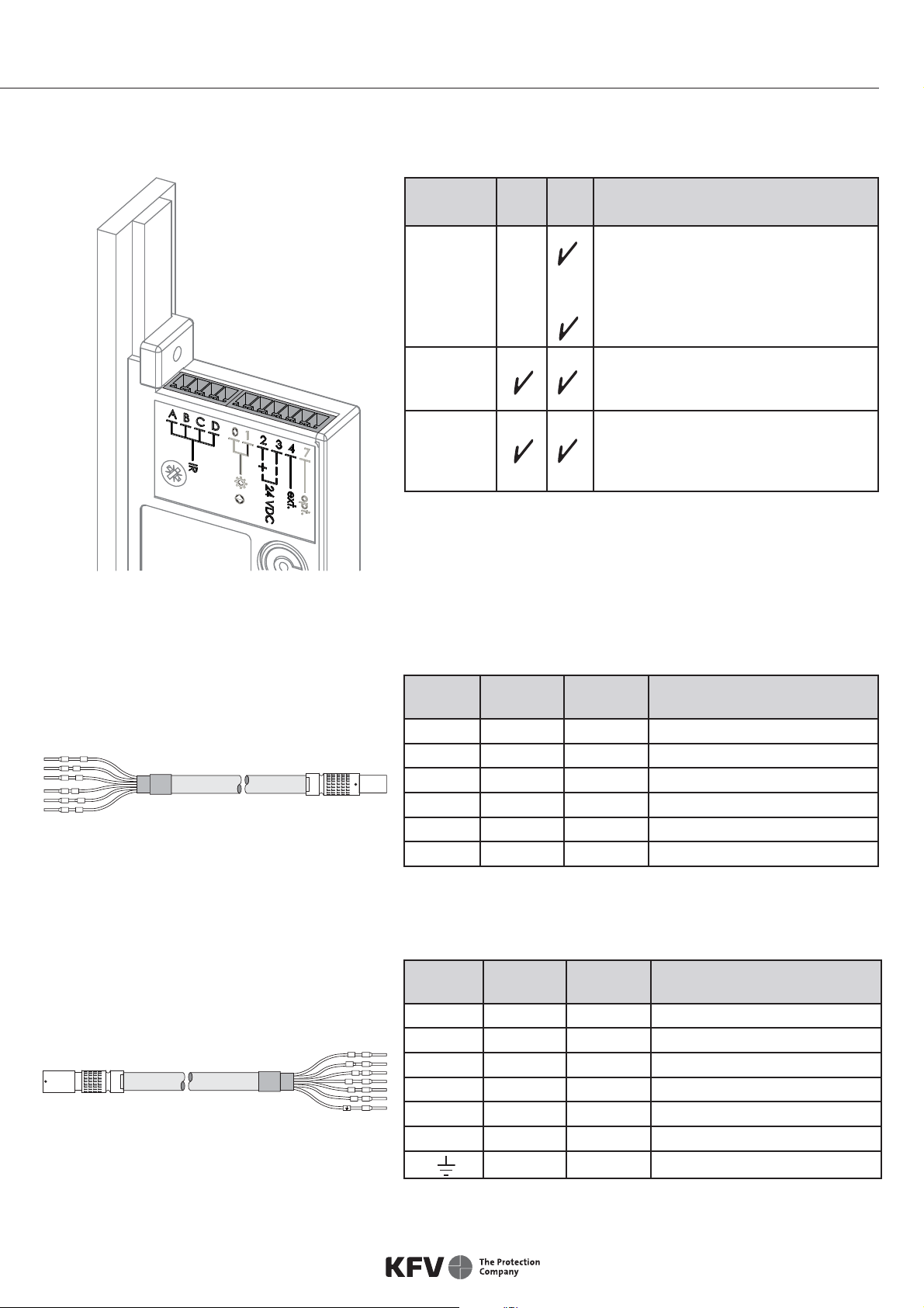
Connections
Connec-
tions
Type
A
Type
BFunction
A, B, C, D
B, C, D, 2
Connection for the infra-red eye, which
sends infra-red signals to the GENIUS
door lock
Connection for the KFV fingerprint
scanner
2, 3
24 V DC operating voltage
Terminal 2 = + (positive)
Terminal 3 = -- (negative)
4
External unlocking signal.
In both operating modes, if +24 V DC
is applied to this terminal for t1 s, the
door will be opened
Fig. 3: Automated latch release connections
Cable types
Type F
Always used together with type B.
0
1
2
3
4
7
Cable
no.
Band
colour
Cable
colour Function
0 Black Grey -
1 Brown Yellow -
2 Red White Operating voltage (+) 24 V DC
3 Blue Brown Operating voltage (--) negative
4 Yellow Green External "unlock" signal
7 Violet Pink -
Fig. 4: Cable type F (for connection of automated
latch release)
Type B
Always used together with type F.
0
1
4
7
+
-
Cable
no.
Band
colour
Cable
colour Function
0 Black Grey -
1 Brown Yellow -
4 Yellow Green External "unlock" signal
7 Violet Pink -
-- Blue Brown Operating voltage (--) negative
+ Red White Operating voltage (+) 24 V DC
White Blue Shield
Fig. 5: Cable type B (for connection of power
supply)

5Last update: 01.08.2013
Assembly instructions Automated latch release
ENGLISH
Type K
Cable
no.
Band
colour
Cable
colour Function
4 Yellow Green External "unlock" signal
-- Blue Brown Operating voltage (--) negative
+ Red White Operating voltage (+) 24 V DC
White Blue Shield
Fig. 6: Cable type K
(connects automated latch release to
power supply)
Type E
Fig. 7: Cable type E (connects automated latch
release to power supply) -type A only-
0
1
2
3
4
7
0
1
4
7
+
-
4
+
4
+
Cable plugs for the automated latch release
UÊ To facilitate installation of the automated latch release, the plug can be removed by pulling it upwards.
UÊ There are letters on the plug to indicate where the various cables should be plugged in.
234
234
ABCD
Type A automated latch release Type F automated latch release
Fig 8: Cable plugs for the automated latch release
Cable
no.
Band
colour
Cable
colour Function
0 Black Grey -
1 Brown Yellow -
4 Yellow Green External "unlock" signal
7 Violet Pink -
-- /3 Blue Brown Operating voltage (--) negative
+/2 Red White Operating voltage (+) 24 V DC
White Blue Shield
6Last update: 01.08.2013
Automated latch release Assembly instructions
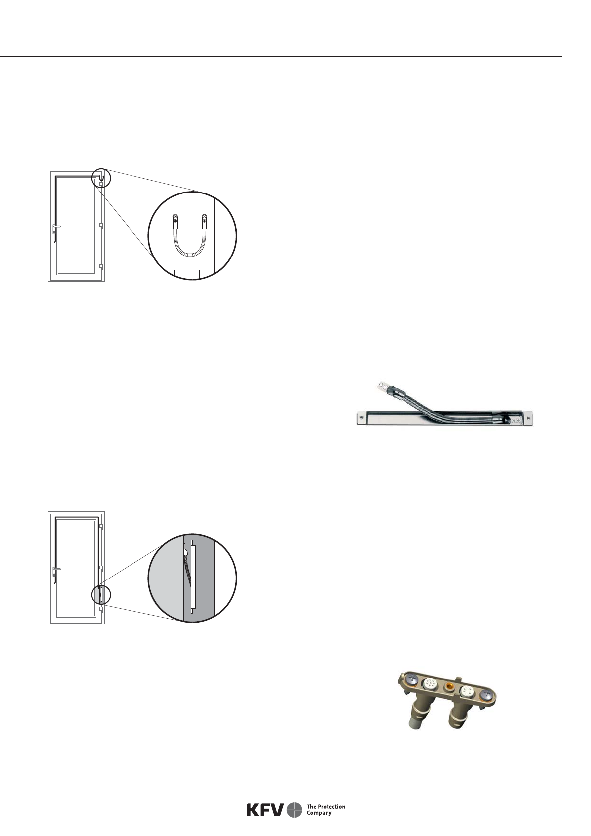
Cable links
Visible cable link
UÊ The visible cable link should be fitted to the inside of the door on the hinge side.
UÊ If this cable link is used, unhinging the door leaf requires substantial effort.
Fig. 9: Visible cable link
Concealed cable links
100° and 180° concealed cable link
UÊ The casing is fitted in the door frame or leaf.
UÊ Allows the door leaf to be unhinged where cable types
B/F are used.
Fig. 10: Concealed cable link, not disconnectable
This cable link is used for routing cables invisibly in the door rebate.
Fig. 11: Concealed cable link
100° and 180° concealed cable link, disconnectable
Cable link is easy to disconnect using the plug connector in the
area of the rebate.
UÊ The casing is fitted in the door frame or leaf.
UÊ The disconnectable cable link permits easy unhinging of
the door leaf. Fig. 12: Concealed cable link, disconnectable
7Last update: 01.08.2013
Assembly instructions Automated latch release
ENGLISH
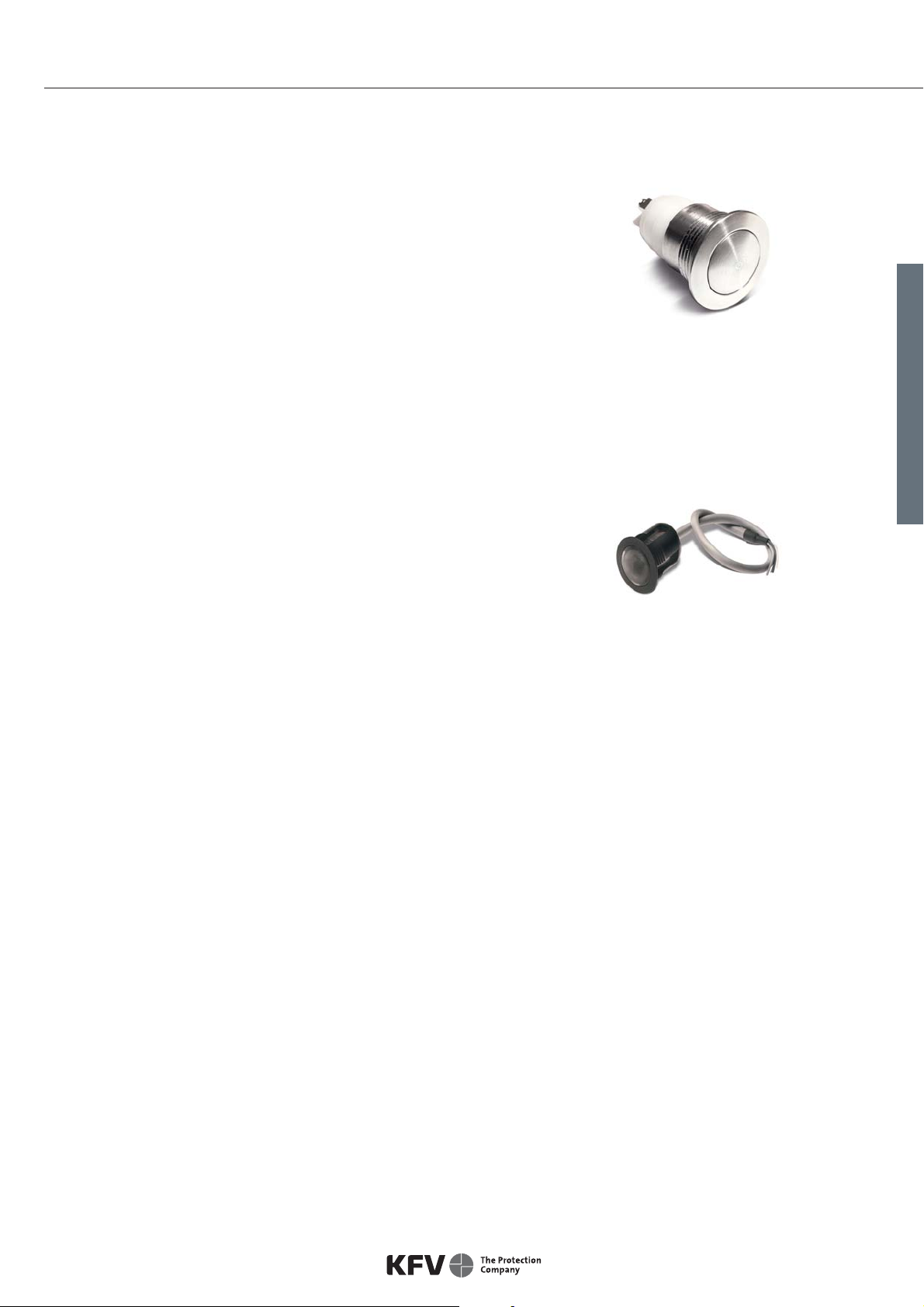
Fitting an internal release push-button (optional)
The internal release push-button can be used to open the door without a
conventional key.
› Connect the cable (length: 750 mm) to terminals 2 and 4 on the auto-
mated latch release.
› Drill an 18 mm (without anchor) or 20 mm (with anchor) drill hole.
Supplied with an anchor for "snap-in" installation.
Anti-intruder advice: To effectively prevent intruders from operating the push-button from the outside, it should be
ensured that any glass panes and infill panels in the door are suitably burglar-resistant.
The infra-red eye acts as a receiver for the infra-red code transmitted by
an infra-red access key or infra-red master key. It comes with an installa-
tion anchor suitable for use in any door material.
› Drill a hole of diameter 20 mm (tolerance ±0.2 mm).
› Push the infra-red eye into the anchor, guiding the cable
(length: 750 mm) in first.
› Guide the cable from the infra-red eye to the automated latch release
and connect it to the terminals on the (4-pin) plug on the automated
latch release.
Fitting the infra-red eye (optional)

8Last update: 01.08.2013
Automated latch release Assembly instructions
Wiring diagram for type A automated latch release
DSP 30
24V DC
Kl. 4 Fl.
( +24 V DC)
234
24VDC
2
4
3
5
6
7
8
1
No. Description
1 230 V AC supply line (L; N; PE)
2 Power supply
3 Wireless receiver (optional)
4 External unlocking (optional)
5 Line length max. 50 metres (external unlocking)
6 Line length max. 13 metres (from automated latch release to power supply)
7 Internal release push-button (optional)
8 Type A automated latch release

9Last update: 01.08.2013
Assembly instructions Automated latch release
ENGLISH
Wiring diagram for type F automated latch release
2
2
3
4
1
37
4
24VDC
45
6
8
7
9
AB CD01
DSP 30
24V DC
Kl. 4 Fl.
( +24 V DC)
2
3
1
No. Description
1 230 V AC supply line (L; N; PE)
2 Power supply
3 Wireless receiver (optional)
4 External unlocking (optional)
5 Line length max. 50 metres (external unlocking)
6 Line length max. 13 metres (from automated latch release to power supply)
7 Infrared eye (optional)
8 Internal release push-button (optional)
9 Type F automated latch release

10 Last update: 01.08.2013
Automated latch release Assembly instructions
Liability
Intended use
Any use of this product that is not in accordance with its intended use, or any adaptation of or modification to the product
and its associated components for which our express consent has not been obtained, is strictly prohibited. We accept no
liability whatsoever for any material losses or injury to people caused by failure to comply with this stipulation.
Product liability
Our products are warranted – subject to correct installation and proper use – for a period of one year from the date of re-
ceipt by a company (according to our general terms and conditions) or as otherwise agreed, and for a period of two years
for end consumers, in accordance with statutory provisions. As part of our ongoing improvements, we reserve the right to
replace individual components or entire products. Consequential losses resulting from defects are excluded from the war-
ranty within the limits of the law. The warranty shall become void if modifications that are unauthorized by us or have not
been described in this documentation are performed on the product and/or individual components, or if the product and/or
individual components is/are dismantled or partly dismantled, and the defect is due to the changes made.
Exclusion of liability
The product and its components are subject to stringent quality controls. As a result, they function reliably and safely when
used correctly. Our liability for consequential losses and/or claims for damages is excluded, except in the case of wilful mis-
conduct or gross negligence, or where we are responsible for injury to life, limb or health. Strict liability under the German
Product Liability Act (Produkthaftungsgesetz) remains unaffected. Liability for the culpable violation of significant contractual
obligations also remains unaffected; liability in this case is limited to losses that are specific to the contract and that could
have been foreseen. The above regulations do not imply a change in the burden of proof to the detriment of the consumer.
Environmental protection
Although our products do not fall within the scope of the German Electrical and Electronic Equipment Act (ElektroG), KFV
will continue to meet the requirements of this Act and will endeavour to completely eliminate the use of substances that are
hazardous to the environment as soon as this becomes technically feasible. Electrical products should not be disposed of as
household waste.
Feedback on documentation
We welcome your comments and suggestions on how to improve our documentation. Please send us your feedback by e-
mail to dokumentation@kfv.de.
We, KFV KG, declare under our own responsibility that this product complies with the provisions of
Directives 2008/108/EC and 2006/95/EC of the Council of the European Union.
EU Declaration of Conformity
Technical specifications
Relative humidity 20 % bis 80 %
Ambient temperature in door -- 10 bis + 45 °C
Dimensions Width 16 mm, length approx. 252 mm, depth 49 mm + width of face plate
Supply voltage 24 V DC max. 500 mA
Cable types
Type LIYCY
Ambient temperature, non-fixed -- 5 bis + 50 °C
Ambient temperature, fixed -- 20 bis + 70 °C
11Last update: 01.08.2013
Assembly instructions Automated latch release
ENGLISH

Contact your dealer:
KFV Karl Fliether GmbH & Co. KG
Siemensstraße 10
42551 Velbert
GERMANY
Telefon: +49 2051 278-0
Telefax: +49 2051 278-167
www.siegenia-aubi.com
SIEGENIA-AUBI worldwide:
Austria Phone: +43 6225 8301
Belarus Phone: +375 17 312 1168
Benelux Phone: +32 9281 1312
China Phone: +86 316 5998198
France Phone: +33 38961 8131
Germany Phone: +49 271 3931-0
Great Britain Phone: +44 2476 622000
Hungary Phone: +36 76 500810
Italy Phone: +39 02 935 3601
Poland Phone: +48 7744 77700
Russia Phone: +7 495 7211762
South Korea Phone: +82 31 7985590
Switzerland Phone: +41 33 346 10 10
Turkey Phone: +90 216 593 4151
Ukraine Phone: +380 44 4637979
H39.ELEKKFV0003EN/2013-08/0
Table of contents
Other Siegenia-AUBI Door Lock manuals


