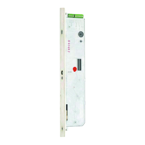
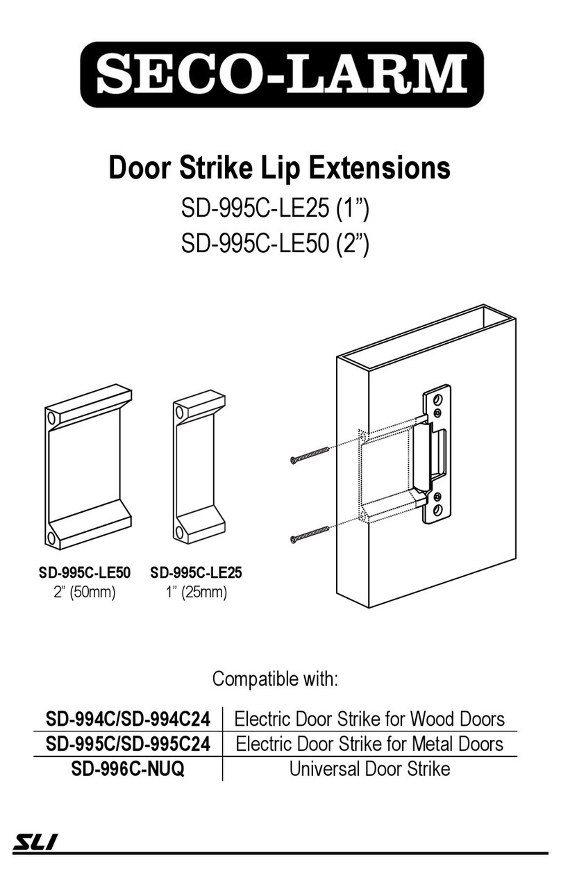
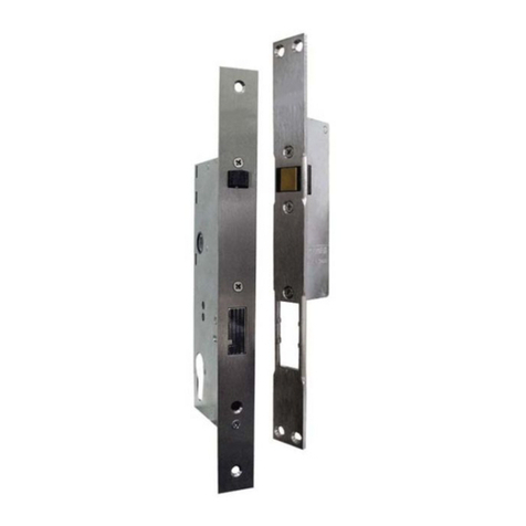
Siegenia-AUBI KFV EE99 Series User manual

Assembly Instructions
WINDOW FITTINGS
DOOR FITTINGS
SLIDING DOOR FITTINGS
VENTILATION AND BUILDING TECHNOLOGY
Emergency Exit and Panic Door Locks:
First leaf (active leaf)


Last update: 30.8.2011 1
Assembly Instructions Emergency Exit and Panic Door Locks
Table of Contents
Feedback on Documentation
We welcome your comments and suggestions on how to improve our documentation. Please send us your
Area of Application of this Document
This documentation is valid for the following listed emergency exit and panic door locks:
• All articles of the series EE99..., EE166..., EE930..., EE950..., EE960...
• All articles of the series PE99..., PE166..., PE930..., PE950..., PE960...
• All articles of the series EP99..., EP166..., EP930..., EP950..., EP960...
• All articles of the series EE25-2F..., PE25-2F..., EP25-2F..., EE26-2F..., PE26-2F..., EP26-2F...
Target Group of this Documentation ................................................................................................. 2
Correct Use ................................................................................................................................... 2
Incorrect Use ................................................................................................................................. 4
Explanation of Symbols................................................................................................................... 4
Screw Recommendation.................................................................................................................. 4
Installation..................................................................................................................................... 5
Assembly Step 1 - Cutting the Door Leaf............................................................................................ 6
Assembly Step 2 - (optional) Predrilling Operating Lever ..................................................................... 7
Assembly Step 3 - (optional) Changing the DIN and Escape Direction .................................................. 8
Assembly Step 4 - Cutting the Door Frame......................................................................................... 9
Assembly Step 5 - Screw Mounting of Components .......................................................................... 10
Assembly Step 6 - Adjusting Strike Plate or Locking Plates.................................................................. 11
Liability....................................................................................................................................... 12
EU Declaration of Conformity ........................................................................................................ 12
Appendix 1: Certificate DIN EN 179 ............................................................................................. 13
Appendix 2: Certificate DIN EN 1125 ........................................................................................... 20

2Last update: 30.8.2011
Emergency Exit and Panic Door Locks Assembly Instructions
Target Group of this Documentation
This documentation is intended to by used by specialists only. All work described in this document is to be
performed by experienced professionals with training and practice in the assembly, installation and mainte-
nance of emergency exit and panic door locks in the corresponding doors. Safe and proper assembly of
these locks is not possible without expert knowledge.
Correct Use
Installation location
• The lock may only be installed in vertically plumb emergency exit or panic doors in stationary buildings.
The following door dimensions must be observed together with the matching lock size:
Door height and width
Handle height Min. door
height Max. door
height Max. door
width
1,020 mm 2,009 mm 2,490 mm 1,320 mm
1,050 mm 2,039 mm 2,520 mm 1,320 mm
Door weight (for classification index, see label on lock case)
Classification index Class Door weight
3rd digit 5max. 100 kg
3rd digit 6max. 200 kg
• The lock may only be installed in doors that have been assembled in a technically sound manner. Door seals
and warping must not result in excessive operating values that would impede the escape function of the lock.
• The door design must permit use of the lock. It is therefore mandatory that you check the following:
- when used in a fire rated or smoke rated door, the lock is suitable for the door according to its certification.
- for double-leaf panic doors with a door closer, especially fire rated and smoke rated doors, a closing
sequence regulator according to EN 1158 and a catch flap are installed to ensure the correct closing
sequence.
- for double-leaf panic doors with a rebated central joint and escapedoor locks fitted on both leafs, it must be
possible to open either leaf with its own lock and to open both leafs when both locks are operated together.
• Most emergency exits and panic doors are installed on the building exterior and open outwards; there are
few exceptions. Ensure construction measures such as erecting a canopy that the lock is not permanently
exposed to the weather so that the function of the lock is not impaired.
• The lock must not be installed:
- in doors made of Accoya
- in swing doors
- in doors of rooms or buildings with an aggressive atmosphere
- in doors of rooms/buildings directly on the coast

Last update: 30.8.2011 3
Assembly Instructions Emergency Exit and Panic Door Locks
Lock, handle/fitting
• The lock forms a unit with the handle/fitting. Only locks and fittings that have been tested together and certified
may be installed. It is not permitted to make changes to such a combination (even partially), or to change the
lock.
• The use of any additional devices to keep the door closed (except a door closer) is not permitted. If a door
closer is installed, it may not impede operation of the door by children, the elderly or infirm.
• Do not attempt to repair the lock. If the lock is damaged, it must be replaced by KFV or repaired by a service
agent authorized by KFV.
•The entire lock must be replaced once it reaches the service life indicated below.
First leaf (“active leaf”) – 1- and 2-leaf doors: 200,000 operations of the handle
Second leaf (“inactive leaf”) – 2-leaf doors: 20,000 operations of the handle
• Replace cylinder locks and keys as soon as there are problems inserting and removing the key despite regular
maintenance.
Cylinder lock
You may use:
• Cylinder lock with free-running lobe in which the lobe can always be freely turned.
• Cylinder lock with rigid lobe in which the lobe is locked in the key removal position within a
range of -30 ° to +30 °.
Fig. 1: Permitted key removal position
You may not use:
• Cylinder locks with rigid lobe in which the lobe is locked in a key removal position outside the range of -30 °
to +30 °. This includes cylinder locks in which the lobe position can be adjusted manually so that a lobe
position outside of the range from -30 ° to +30 ° is possible to reach.
Opening/Closing/Locking
• It must be possible to open and close the door easily. A protruding latch and/or locking bolt must not impede
the opening of the door.
• The locking elements must always engage freely in the perforations of the locking parts.

4Last update: 30.8.2011
Emergency Exit and Panic Door Locks Assembly Instructions
Incorrect Use
A misuse/improper use of the lock is present if, for example:
• foreign objects are inserted into the lock, its fittings or frame parts (closing plate or locking rail).
• alterations are made to the lock, its fittings or frame parts that affect the operation, design or function of the
lock.
• the activated locking bolt is misused to hold the door open.
•moving or adjustable parts of the lock (e.g. locking bolt, latch), fitting or frame are treated after installation in
a way that impairs their function (e.g. varnishing the parts).
• loads in excess of normal manual force are applied to the lever handle or operating handle.
• unsuitable closing means are used, e.g. deviating in dimension or with the incorrect setting.
• the clearance between the door and the frame increases or decreases when the lock, fitting or frame is
adjusted, or when the door is lowered.
• a 2-leaf door not suitable for the purpose its forced open by the second leaf (“inactive leaf”).
• objects are inserted between door leaf and door frame when the door is closing.
• the door is opened simultaneously with the lever handle and the key,
• the door is carried by the lever handle or fitting when being transported.
• force is applied to the lock, fitting or frame parts.
Explanation of Symbols
Ø16
cutter or drill diameter through hole
180
groove length for metal profiles
50
groove depth from component for wood profiles
50
groove depth from profile for plastic profiles
Screw Recommendation
3,9
4,0
3,9

Last update: 30.8.2011 5
Assembly Instructions Emergency Exit and Panic Door Locks
Installation
Installation conditions and requirements
Local building laws and regulations must be observed before and during door installation in addition to the
following requirements and conditions:
• Before installing the lock, check the dimensional accuracy of the door and the door frame. The lock must not
be installed if the door or the frame is warped and/or damaged.
• Install the lock and accessories (e.g. rotary spring) according to our assembly instructions. Use the supplied
fastening material for assembly.
• Remove any waste material from the lock mortise after cutting.
• Do not perform mechanical work on the door (e.g. drilling, cutting) when the lock is installed. Never drill or
drill through the main lock.
• Observe the specified positions and sizes when drilling the holes. Use the supplied jig when drilling the holes
manually.
• Follow the information of the fitting manufacturer when drilling the holes for the operating lever/fitting.
• Install fittings and cylinder flush without overtightening the screws or screwing them in at an angle.
• Fasten handle set only by hand and do not use force when installing the spindle.
• Install the horizontal operating lever between 900 and 1,100 mm above the finished floor level with the door
closed. If it is known that the users of the building are mainly small children, adjust the installation height of the
operating lever based on a risk analysis and in cooperation with the responsible authorities.
• Fix the horizontal operating lever so that the maximum possible effective handle length is achieved.
• Install any stop elements and stop counterparts so that the handle can be safely engaged. Free movement of
the door must not be impeded by projection of the stop elements in the retracted position.
• Keep the distance between the face plate and locking parts: for 1-leaf doors: 2 to 6 mm
for 2-leaf doors: 4 to 6 mm
• Operating elements may not impede each other.
• Check the correct setting of any existing filling.
• Adjusted hinges and interlocking leafs must make it possible to open both door leafs at the same time.
• Surface treatment of the door and door frame must take place before the lock is installed. Treating the surface
at a later stage can reduce the functional capacity of the lock.
• Use only acid-free vulcanized sealants to prevent corrosion of components and/or the door.
Dimensions
All dimensions given in this documentation are in mm.

6Last update: 30.8.2011
Emergency Exit and Panic Door Locks Assembly Instructions
Assembly Step 1 - Cutting the Door Leaf
BC
G
A
D
20
50
180
Ø16
Ø 18
Ø 11
145
D+20
250
Ø16
50
180
Ø16
Dimensions
B version A B C G
B001 2170 760 730 1020
B002 2170 760 730 1050
B003 2400 760 980 1020
B039 1700 760 355 952
B041 1700 760 605 952
B166 1855 760 730 952
B253 2170 760 980 952
B296 2170 760 355 1020
B298 2170 760 605 1020

Last update: 30.8.2011 7
Assembly Instructions Emergency Exit and Panic Door Locks
Assembly Step 2 - (optional) Predrilling Operating Lever
4
Ø 5
Assemblyaccordingtothefitting
manufacturer's instructions.

8Last update: 30.8.2011
Emergency Exit and Panic Door Locks Assembly Instructions
Assembly Step 3 - (optional) Changing the DIN and Escape Direction
180°
4 - 5 x
1.
2.
3.
4.
DIN direction (changing the latch) Changing the escape direction
1.
2.
3.
4.

Last update: 30.8.2011 9
Assembly Instructions Emergency Exit and Panic Door Locks
Assembly Step 4 - Cutting the Door Frame
21
21
23
BC
30
135
Ø16
30
72
Ø16
30
62
Ø16
30
135
Ø16
Dimensions
B version B C
B001 760 730
B002 760 730
B003 760 980
B039 760 355
B041 760 605
B166 760 730
B253 760 980
B296 760 355
B298 760 605

10 Last update: 30.8.2011
Emergency Exit and Panic Door Locks Assembly Instructions
Assembly Step 5 - Screw Mounting of Components
Strike plate or locking plates Multipoint lock

Last update: 30.8.2011 11
Assembly Instructions Emergency Exit and Panic Door Locks
Assembly Step 6 - Adjusting Strike Plate or Locking Plates
± 2,5
2,5
2,5
2,5
1.
2.
3.

12 Last update: 30.8.2011
Emergency Exit and Panic Door Locks Assembly Instructions
Liability
Intended use
Any use or application of this product that is not in accordance with its intended purpose, or any adaptation
of or modification to the product and its associated components, for which the express consent of us has not
been obtained, are strictly prohibited. We are not liable for any damages to material or persons if these
directions are not observed.
Product liability
Provided that they are properly installed and correctly handled, our products are subject to warranty for
1 year after receipt of goods by companies (according to our general terms and conditions), or as otherwise
agreed, and for 2 years for end consumers according to statutory law. As part of our ongoing improvements,
we reserve the right to replace individual components or entire products. Consequential losses resulting from
a failing in the unit are excluded from the warranty within the limits of the law. The warranty shall become
void if modifications that are unauthorized by us or have not been described in this documentation are made
to the product and/or individual components, or if the product and/or individual components is/are disman-
tled or partly dismantled.
Disclaimer of liability
The product and its components are subject to stringent quality controls. As a result, they function reliably and
safely when used properly. Our liability for consequential losses and/or claims for damages is excluded,
except in the case of wilful misconduct or gross negligence, or where we are responsible for injury to life,
limb or health. Strict liability under the German Product Liability Act (Produkthaftungsgesetz) remains unaf-
fected. Liability for the culpable violation of significant contractual obligations also remains unaffected; lia-
bility in this case is limited to losses that are specific to the contract and that could have been foreseen. The
above regulations do not imply a change in the burden of proof to the detriment of the consumer.
EU Declaration of Conformity
We, KFV Karl Fliether GmbH & Co. KG, declare under sole responsibility that the product
meets the regulations of Directive 93/68/CEE of the Council of the European Union.

Last update: 30.8.2011 13
Assembly Instructions Emergency Exit and Panic Door Locks
Appendix 1: Certificate DIN EN 179

14 Last update: 30.8.2011
Emergency Exit and Panic Door Locks Assembly Instructions

Last update: 30.8.2011 15
Assembly Instructions Emergency Exit and Panic Door Locks

16 Last update: 30.8.2011
Emergency Exit and Panic Door Locks Assembly Instructions

Last update: 30.8.2011 17
Assembly Instructions Emergency Exit and Panic Door Locks

18 Last update: 30.8.2011
Emergency Exit and Panic Door Locks Assembly Instructions
This manual suits for next models
19
Table of contents
Other Siegenia-AUBI Door Lock manuals
