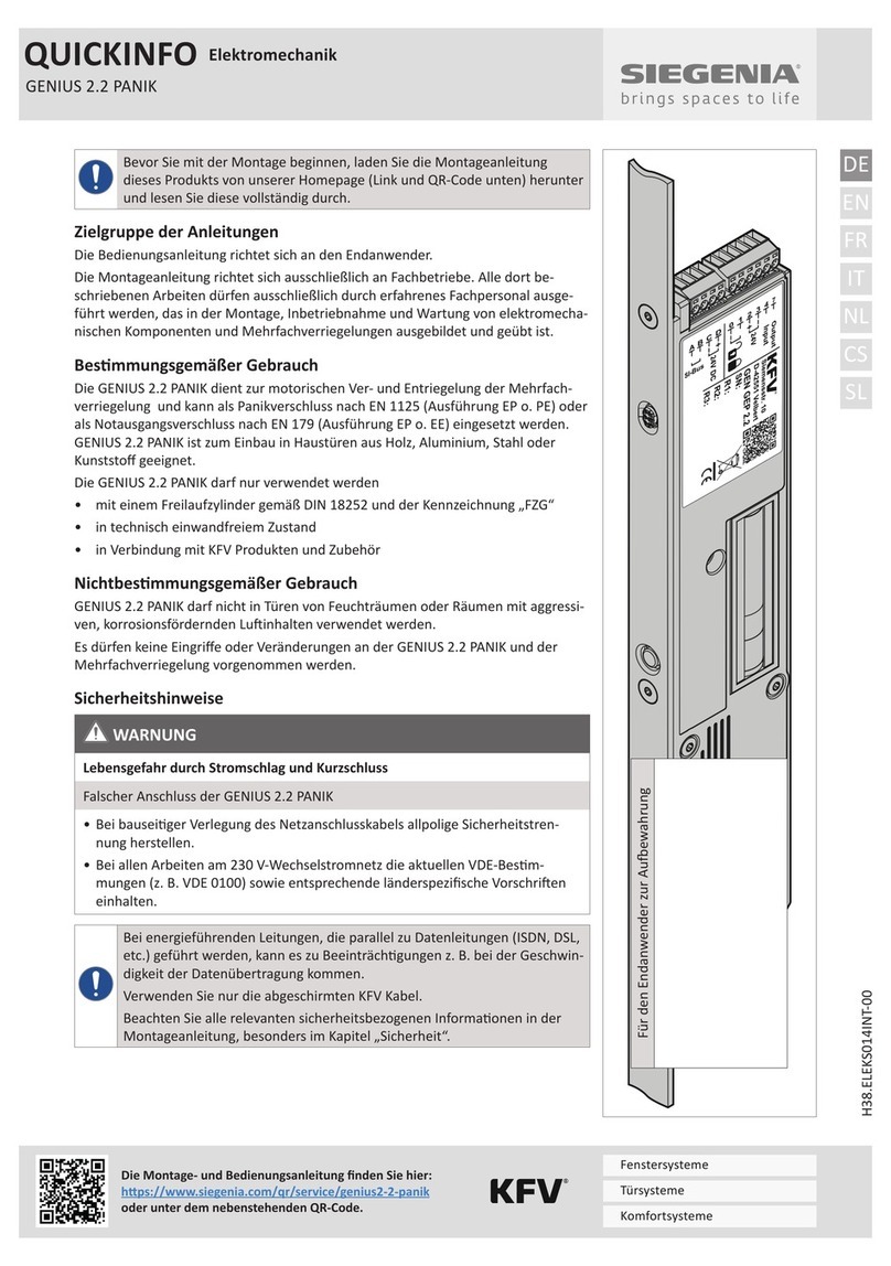
Siegenia KFV A-Opener 2.2 User manual

ASSEMBLY INSTRUCTIONS
KFV
Electro-mechanical systems
Comfort systems
Door systems
Window systems


3/20
Electro-mechanical systems
3/20
Inhalt
1 INTRODUCTION.........................................4
4
4
4
4
4
4
4
4
4
2 SAFETY.......................................................5
3 INSTALLATION CONDITIONS AND REQUI
REMENTS...................................................6
4 FUNCTIONS................................................7
5 INSTALLATION .........................................10
6 FUNCTIONAL TEST...................................13
handle:

Electro-mechanical systems
4/20
1
-
1.1 Producer and service
-
1.2
-
-
maintenance of electromechanical components and
1.3 Intended use
•
•
–
–
–
–
–
1.4 Improper use
•
–
– in doors for wet rooms or rooms in which the air
•
1.5 Maintenance and service notes
-
1.6
1.7 Dimensions
1.8 Symbols used
1.9 Other types of indicators
•
–
f
Cross reference

/20
Electro-mechanical systems
/20
1.10 Applicable documents
1.11 Appropriate disposal
-
2 Safety
•
• -
• -
•
2.1 Structure of the warning notes
•
•
•
•
•
principle:
SIGNAL WORD
Type and source of danger
•
-
-
2.2 Warning notes used
DANGER
WARNING
CAUTION
NOTICE
-
2.3 Warning notes
WARNING
Risk of fatal injury from electric shock and short circuit
•
•
-

Electro-mechanical systems
/20
3 -
ments
•
•
• -
•

/20
Electro-mechanical systems
/20
4
4.1
A
SI-Bus
Siemensstr. 10
D-42551 Velbert
A-OPENER 2.2
SN:
R1:
R2:
R3:
24V DC
GND
24V DC
GND
Input
B C D 2 3 4
3
3
4
2
Item
-

Electro-mechanical systems
/20
4.2 Cable and wiring diagram
WARNING
Risk of fatal injury from electric shock and short circuit
•
• -
4
3
2
4
3
2
Item Name
2
3
4
Item Name
2
3
4

9/20
Electro-mechanical systems
9/20
A
SI-Bus
Siemensstr. 10
D-42551 Velbert
A-OPENER 2.2
SN:
R1:
R2:
R3:
24V DC
GND
24V DC
GND
Input
B C D 2 3 4
> = 1s
> = 1s
+V
L
N
PE
-V
A
SI-Bus
Siemensstr. 10
D-42551 Velbert
A-OPENER 2.2
SN:
R1:
R2:
R3:
24V DC
GND
24V DC
GND
Input
B C D 2 3 4
2
3
Item Name
Item Name
2
3

Electro-mechanical systems
/20
5
5.1 Installing the A-opener
-
f
5.2 Milling the door leaf
2
4
3
Dimensions of the routed pocket

/20
Electro-mechanical systems
/20
5.3
A
SI-Bus
Siemensstr. 10
D-42551 Velbert
A-OPENER 2.2
SN:
R1:
R2:
R3:
24V DC
GND
24V DC
GND
Input
B C D 2 3 4
-
-
5.3.1
2
3
f
-
f

Electro-mechanical systems
/20
5.3.2
KFV cable -
Band colour Cable colour
0
1
4
7
+
-
0 - -
Yellow - -
4 Yellow
- -
White
-
White - -
+
-
4
2
+
-4
f
f
+
-4
+
-4
f
f

/20
Electro-mechanical systems
/20
6
•
•
•
6.1
6.1.1
f
6.1.2 -
der
f-
f-
f
f
6.1.3
A-opener 2.2
the lever handle
f
f
f
f
f
the key
f
f
f
6.2
f
f
f
6.3 Electromechanical test
f
f
f-
f
-

Electro-mechanical systems
/20
6.4
6.4.1
-
f
f
f
-
6.4.2
f
f
f

/20
Electro-mechanical systems
/20
6.5
Electrical data
Input signal terminal 4
Dimensions
Dimensions
Cable lengths

Electro-mechanical systems
/20
6.6
Electromechanical drive for mul-
A-opener 2.2
-

Table of contents
Other Siegenia Industrial Electrical manuals
Popular Industrial Electrical manuals by other brands

Murata
Murata GRM32AR61C106KAB7 Series Reference sheet

Murata
Murata GRM0335C1H2R4CA01 Series Reference sheet

Siemens
Siemens SIVACON 8PS installation instructions

GREER Company
GREER Company MICROGUARD 434 troubleshooting manual

Murata
Murata GRM188R71H472JA01 Series Reference sheet

Keysight
Keysight 849 Series Operating and service manual

GE
GE QuiXtra 630 Assembly and mounting instructions

Powell
Powell FlexGear Instruction bulletin

Murata
Murata GJM1555C1H8R5BB01 Series Reference sheet

Murata
Murata GRM1887U1H332JA01 Series Reference sheet

Murata
Murata GRM1885C1H681JA01 Series Reference sheet

Murata
Murata GRM0225C1C220JA02 Series Reference sheet