Siemens Energy DigiTRONf DFRV Series User manual

Unrestricted
Lorem ipsum l Veribus
dolorpro
DigiTRONf
Installation, Operations and
Maintenance Manual
IOM-008 Rev 5
DigiTRONfEFL’s, Jumpers and Harness Assemblies
Protection, Storage, Shipment, Unpacking, Deployment and
Maintenance Instructions
siemens-energy.com

Document No:
IOM-008
Issue Date:
17/03/2023
Revision:
05
Page:
2 of 43
Unrestricted
DigiTRONfEFL’s, Jumpers and Harness Assemblies
Protection, Storage, Shipment, Unpacking, Deployment and
Maintenance Instructions

Document No:
IOM-008
Issue Date:
17/03/2023
Revision:
05
Page:
3 of 43
Unrestricted
Thank you for purchasing a Siemens Energy Subsea product. The information contained in this
document is an overview including the protection, storage, shipment, unpacking, deployment and
maintenance for DigiTRON connector product range.
IMPORTANT
READ CAREFULLY BEFORE USE
KEEP FOR FUTURE REFERENCE
Rev
Compiled
by
Date
Approved
by
Issue Date
Page(s) Affected/Remarks
01
M Tucker
09.11.2020
R Wyatt
09.11.2020
First issue
02
J.Pridmore
23/08/2021
M.Tucker
23/08/2021
Etching detail updated
Connector Specification updated with
Physical Contact type and No. of ways
Extra abbreviations added to section 4
Images updated to show latest paddle handle
Storage Temperature range added for
Mate/De-mate tool
03
J.Pridmore
31/08/2021
M.Tucker
31/08/2021
Junction Box interface drawing changed to
10199114
04
R Wyatt
27/06/2022
R Wyatt
27/06/2022
Sections affected: 2.4 3.3.5 5.1 5.2 6.3
6.4.1 6.4.2 6.4.3 7.3.2 7.3.3
Siemens Energy front and back cover pages
added.
05
R Wyatt
17/03/2023
JP Smith
17/03/2023
Sections affected: 2.2, 6.1, 6.2, 6.4, 7.4, 8.2, 9.5
9.7, 9.8. Information added or changed:
temperature limits for storage 50°C air temp.
Outdoor storage of wooden crates. Bend radius
guage and protection from crate edges. Check for
test connectors, incl gauge for bent pins. Inspection
for corrosion, damage to front seals added.
Cleaning with IPA added. Visibility of lipseal
indicator from side view.

Document No:
IOM-008
Issue Date:
17/03/2023
Revision:
05
Page:
4 of 43
Unrestricted
Contents
1PRODUCTS COVERED BY THIS MANUAL..............................................................6
2BASIC INFORMATION & QUICK REFERENCE........................................................7
2.1 Product overview..............................................................................................7
2.2 Product specification and certification...........................................................8
2.3 Contact details and feedback ..........................................................................9
2.4 Product advice label.........................................................................................9
2.5 Product marking .............................................................................................10
2.6 Product examples...........................................................................................11
3PRODUCT SAFETY .................................................................................................13
3.1 Action-related warnings.................................................................................13
3.2 Intended use....................................................................................................13
3.3 General safety information.............................................................................14
3.4 Related documents.........................................................................................16
3.5 Control of substances hazardous to health (COSHH).................................17
4ABBREVIATIONS.....................................................................................................18
5SPECIFICATIONS ....................................................................................................19
5.1 Connector Specification.................................................................................19
5.2 Siemens Energy AquaTRON pressure-balanced oil-filled hose
specification ............................................................................................................20
6PREPARING PRODUCT FOR USE OR STORAGE ................................................21
6.1 Product protection and packaging................................................................21
6.2 Unpacking........................................................................................................22
6.3 Lifting of harnesses and OFLs ......................................................................22
6.4 Storage, protection and end of life................................................................23
7INSTALLATION AND ASSEMBLY ..........................................................................26
7.1 Pre-installation checks for OFL’s ..................................................................26
7.2 Cathodic protection........................................................................................26
7.3 Installation of harnesses with flanged connectors and / or Fiber
Marshalling Unit ......................................................................................................26
7.4 TESTING OF OFL’S.........................................................................................30
8USER INFORMATION DURING NORMAL OPERATION AND FAULT CONDITIONS
..................................................................................................................................32
8.1 Visible/audible signals ...................................................................................32
8.2 Normal and faulty/dangerous operation.......................................................32
8.3 Troubleshooting..............................................................................................32
9PRODUCT OPERATION AND MAINTENANCE ......................................................33
9.1 Safety precautions..........................................................................................33
9.2 Product maintenance and servicing .............................................................33

Document No:
IOM-008
Issue Date:
17/03/2023
Revision:
05
Page:
5 of 43
Unrestricted
9.3 Product protection; caps and dummy connectors ......................................33
9.4 Live Mate / De-mate ........................................................................................34
9.5 Inspection and cleaning of connector products ..........................................34
9.6 Removal of marine growth and calcareous deposits ..................................34
9.7 Checks before mating the product................................................................36
9.8 ROV connectors mating and de-mating........................................................36
9.9 Manual (hand) mating and demating of the connectors..............................38
10 CUSTOMER COMMENTS/FEEDBACK...................................................................42
Tables
Table 1 List of other Installation, Operation and Maintenance manuals related to
DigiTRON product range..................................................................................................... 6
Table 2 DigiTRONf product range identification......................................................7
Table 3 DigiTRONf product specification and certification.....................................8
Table 4 DigiTRON product contact details............................................................... 9
Table 5 AquaTRON oil-filled hose specification.....................................................20
Table 6 Troubleshooting product contact details.................................................. 32
Illustrations
Figure 1 Product advice label ................................................................................... 10
Figure 2 Product marking on DigiTRON product.....................................................10
Figure 3 Typical OFL (Optical Flying Lead)..............................................................11
Figure 4 Example of OFL........................................................................................... 11
Figure 5 Typical multi-leg OFL or harness assembly.............................................. 12
Figure 6 Typical AFT to Receptacle (1out harness) assembly ............................... 12
Figure 7 Examples of DigiTRONf oil hose connectors............................................12
Figure 8 AquaTRON hose, size 50 (1/2” bore), and size 75 (3/4” bore) .................. 20
Figure 9 Acceptable packaging for shipment.......................................................... 21
Figure 10 Unacceptable packaging and storage ....................................................... 22
Figure 11 Minimum bend radius gauges.................................................................... 22
Figure 12 Illustration of strapping points for lifting hose assemblies.....................23
Figure 13 Installation of compliant flange-mount ROV receptacle........................... 27
Figure 14 Sectional view of installation and parts of compliant mount connector. 27
Figure 15 Junction box mounting horizontal (left) and vertical (right) ....................28
Figure 16 Junction box mounting bracket assembly................................................ 29
Figure 17 FMU correctly installed on structure......................................................... 29
Figure 18 Test harnesses............................................................................................ 31
Figure 19 Transport Caps (left) and Protective Caps (right)..................................... 33
Figure 20 Typical subsea protection caps................................................................. 34
Figure 21 Permissible Water Jetting ..........................................................................35

Document No:
IOM-008
Issue Date:
17/03/2023
Revision:
05
Page:
6 of 43
Unrestricted
1 PRODUCTS COVERED BY THIS MANUAL
This manual includes information on DigiTRONfproduct range of optical flying leads (OFL), jumper
and harnesses, including connectors that are part thereof, their optical andmechanical specification.
Also this manual provides details of installing the DigiTRON product range of connectors that are
fitted as part of an oil filled hose or cable assembly.
Installation, Operation and Maintenance manuals for other DigiTRON products not covered by this
document can be found on Siemens Energy Subsea website www.siemens-energy.com /search
Subsea, as listed in Table 1.
If a non-Siemens connector is fitted as part of the OFL or harness, then the manufacturer of that
product should be contacted for the IOM manual.
DOC. No.
PRODUCT
IOM-002
DigiTRON single connectors
IOM-003
Obsoleted, replaced by IOM-002.
IOM-004
Not used
IOM-005
Retrievable Electrical Distribution unit (REDU), 2nd generation
IOM-006
Retrievable Electrical Distribution unit (REDU), 1st generation
IOM-007
Disconnectable junction boxes type TC3A-107 and similar Electrical
Distribution Units (EDUs).
IOM-009
DigiTRONf single connectors
00003075
Subsea PT/TT sensors
00007464
Differential Pressure sensors SDP-6 / SDP-8
Table 1 List of other Installation, Operation and Maintenance manuals related to DigiTRON
product range

Document No:
IOM-008
Issue Date:
17/03/2023
Revision:
05
Page:
7 of 43
Unrestricted
2 BASIC INFORMATION & QUICK REFERENCE
2.1 Product overview
DigiTRONfconnectors, optical flying leads (OFLs), jumpers and harness assemblies intended use
is to provide communications and optical data links between pieces of optical equipment that are
submerged in water, e.g. subsea.
The DigiTRONfrange of connectors have been developed for long term reliable optical
communications in subsea applications. The underwater mateable capacity of these connectors is
achieved using pressure compensated optical inserts employing the ‘controlled environment’ CE
principle.
An OFL is completely independent of other equipment, and is fitted with ROV or Diver installable
connectors at each end. All OFL’s are oil filled pressure compensated hose assemblies and are
supplied as complete finished product from the factory.
All OFL’s should be retrievable and when installed should not cross-over each other.
Some illustrations are shown in section 2.6 to help identify an OFL and jumper (harness).
Table 2 below identifies each product type in the DigiTRONf product range.
The products look very similar, so it is important to note the identifier for each product type.
Product
range
Description
Typical part number
(etched on the connector)
DigiTRONf
12-way fibre optic
wet-mate connector
DFRV-….….
DFST-.…….
DFDV- ........
Table 2 DigiTRONf product range identification

Document No:
IOM-008
Issue Date:
17/03/2023
Revision:
05
Page:
8 of 43
Unrestricted
2.2 Product specification and certification
Basic specifications relating to all products covered by this manual are below in Table 3. Additional
specifications can be found in section 5.
Design Life:
30 years in subsea environment
Optical Performance
1550nm and 1625nm
Insertion loss - typically ≤0.2dB [max 0.5dB, 75% ≤0.4dB]
Return loss - typically ≥70dB [min 45dB, 75% ≥55dB]
Cross-talk ≤ -60dB
Rated number of
operations
1000 (750dry/250wet) mate / de-mate cycles
Water depth
4,000 m (13,123ft)
Storage temperature
-40°C +70°C (-40°F +158°F) (upper limit is surface temperature of the
product and includes solar gain from bright sunlight)
Recommended maximum ambient air temperature +50°C (122°F).
Operational temp
Subsea: -5°C +50°C (+23°F +122°F)
In air: -20°C +50°C (-4°F +122°F)
Product Certification:
Standard
Description
API-17F
Standard for Subsea Production Control Systems
Note: Self-certified via in-house testing.
Table 3 DigiTRONf product specification and certification
Document No:
IOM-008
Issue Date:
17/03/2023
Revision:
05
Page:
9 of 43
Unrestricted
2.3 Contact details and feedback
For additional information or questions regards the products visit the Siemens Energy Subsea
website https://www.siemens-energy.com /search Subsea, or contact the following
Department
E-mail address
Product Safety Officer
subsea.connectors.productsafety.gb@siemens-
energy.com
Technical Support
connectortechnicalsupport.gb@siemens-energy.com
Service (Site Team)
susultlcmsupport.gb@siemens-energy.com
Sales
connectorsales.gb@siemens-energy.com
Table 4 DigiTRON product contact details
Any information, records, or Health and Safety feedback that needs to be detailed can be recorded
in section 10 of this document and sent to the relevant department in Table 4
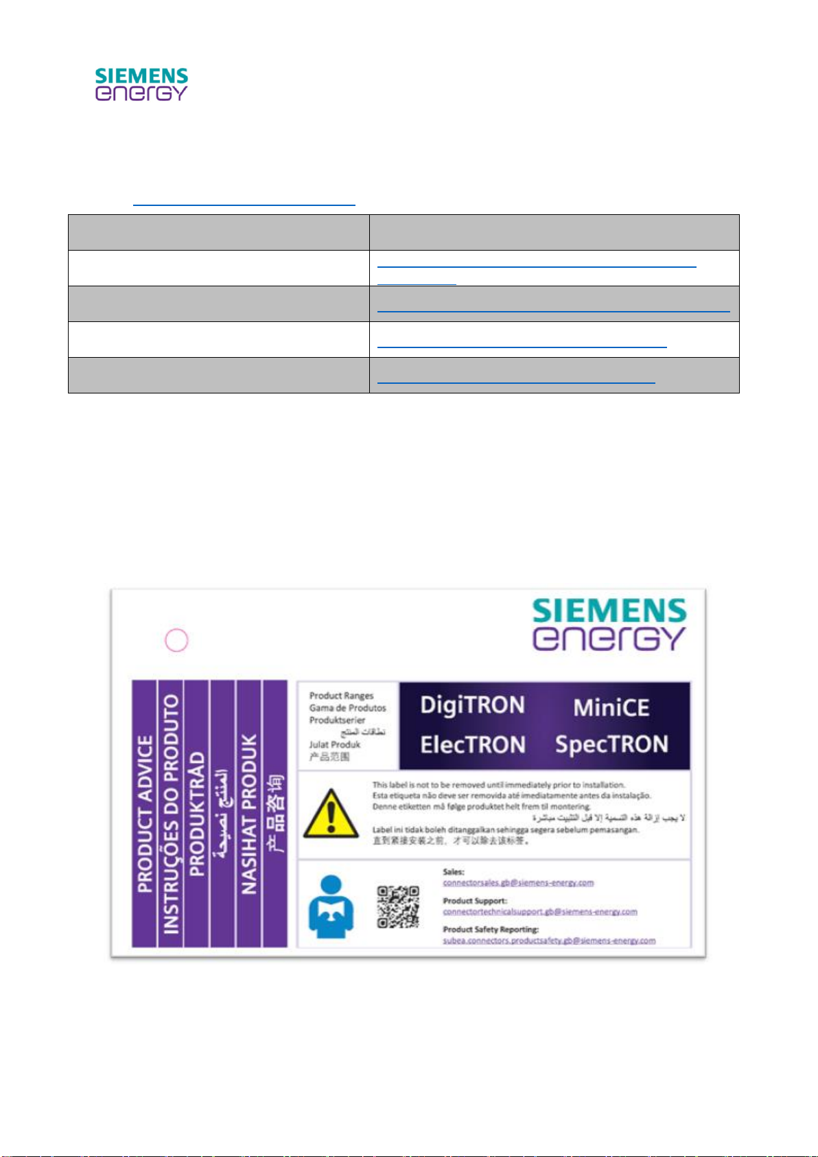
2.4 Product advice label
The following product advice label is supplied with all Siemens Energy Subsea products.
Document No:
IOM-008
Issue Date:
17/03/2023
Revision:
05
Page:
10 of 43
Unrestricted
Figure 1 Product advice label
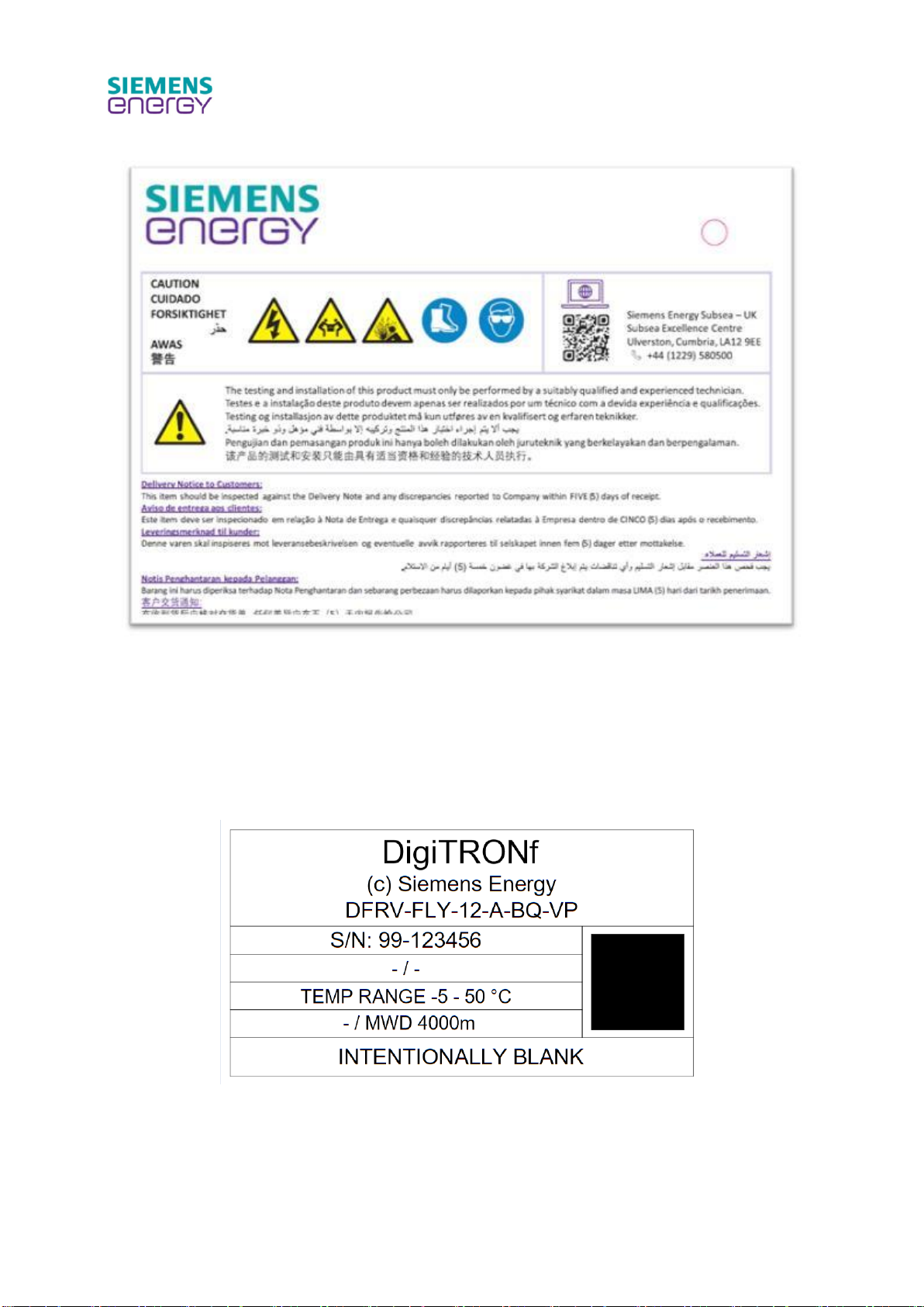
2.5 Product marking
Siemens Energy Subsea DigiTRON products are marked with the Siemens Energy part number and
unique serial number. Also, the voltage, temperature andwater depth ratings areindicated. Marking
locations are typically on the metal bodies of the connectors. Refer to Figure 2.
Figure 2 Product marking on DigiTRON product
Harnesses are also marked with the Siemens Energy Subsea unique serial number.
Labels are typically black text on a yellow background underneath a clear protective wrap and are
typically located at each end of the harness and centrally. Often client’s own information is added
to these labels.
Document No:
IOM-008
Issue Date:
17/03/2023
Revision:
05
Page:
11 of 43
Unrestricted
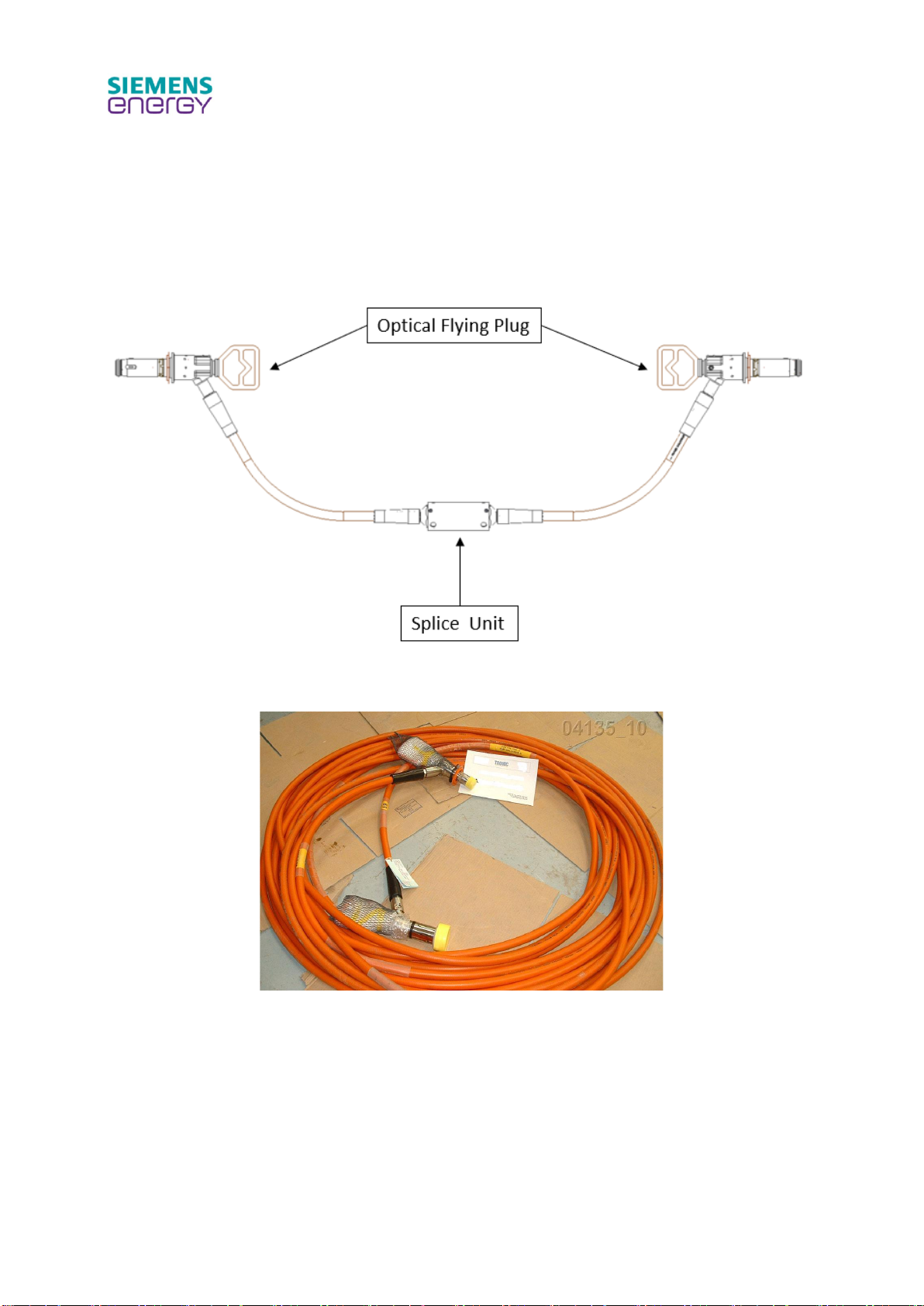
2.6 Product examples
An OFL shown in Figure 3 and Figure 4 always has at least on splice unit, which could be located at
different positions along the hose. Two splice units are needed for lengths in excess of 45m (150
ft).
Figure 3 Typical OFL (Optical Flying Lead)
Figure 4 Example of OFL
Multi-legged harness is shown in Figure 5. There can be up to four legs on each side of the Fiber
Marshalling Unit (FMU). Each hose can be fitted with a flying plug or a flange-mounted receptacle.

Document No:
IOM-008
Issue Date:
17/03/2023
Revision:
05
Page:
12 of 43
Unrestricted
Figure 5 Typical multi-leg OFL or harness assembly
To terminate FOcables laid up in an umbilical cable (e.g. steel orcopper tubes containing the optical
fibers) an Advanced Fiber Termination Unit (AFT) is used. This crosses over from the umbilical
cable to the oil-filled hose system. The AFT can have up to 4 hose outputs. Single output example
is shown in Figure 6
Figure 6 Typical AFT to Receptacle (1out harness) assembly
Figure 7 Examples of DigiTRONf oil hose connectors
Document No:
IOM-008
Issue Date:
17/03/2023
Revision:
05
Page:
13 of 43
Unrestricted
3 PRODUCT SAFETY
Siemens Energy Subsea recommends the termination of all equipment shall only be undertaken by
trained, suitably qualified and experienced personnel (SQEP) i.e. competent person.
Following installation, commissioning or deployment of product, if you have any feedback please
complete and return the Customer Comments/Feedback form (Section 10). Please e-mail completed
form to the Product Safety Officer at subsea.connectors.productsafety.gb@siemens-energy.com
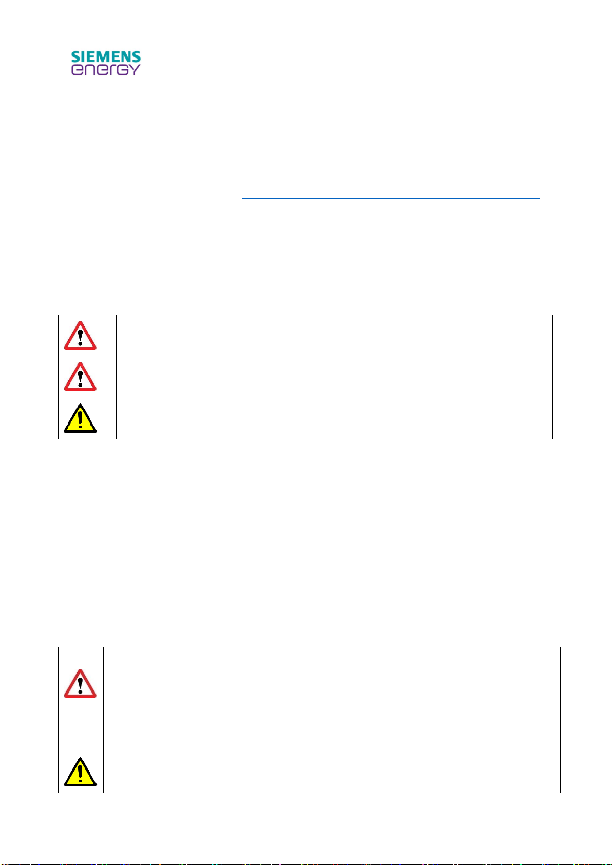
3.1 Action-related warnings
Classification of action-related warnings
The action related warnings are classified in accordance with the severity of the possible danger
using the following warning signs and signal words:
Warning symbols and signal words
Danger!
Imminent danger to life or risk of severe personal injury
Warning.
Risk of minor personal injury
Caution.
Risk of material or environmental damage
3.2 Intended use
The product is intended as a Low fibre optic connection system for subsea use
There is a risk of injury or death to the user or others, or of damage to the product and other property
in the event of improper use or use for which it is not intended.
Intended use includes the following:
- observance of the installation and operating instructions included for the product and any other
system components.
- compliance with all inspection and maintenance conditions listed in the instructions.
- use of all recommended tooling appropriate for specific tasks.
- all activities to be undertaken by a competent person (see 3.3.1 for definition).
Any other use that is not specified in this document or covered in installation and operating
instructions, or beyond that specified in this document shall be considered improper use.
Danger! Risk of imminent danger to life or risk of severe personal injury.
Sudden release of stored pressure.
DigiTRON products are not intended for use as a penetration for fixed top-side or land-
based pressure vessels. They are not designed to comply with the requirements of the
Pressure Equipment Directive (2014/68/EU). They are intended for integration into
subsea equipment only.
All pressure testing of DigiTRON product must be undertaken by a competent person.
Caution. Risk of material or environmental damage, improper use of any kind is prohibited.
Document No:
IOM-008
Issue Date:
17/03/2023
Revision:
05
Page:
14 of 43
Unrestricted
3.3 General safety information
Installation by competent persons only
The installation, inspection, maintenance and repair of the product shall be undertaken by trained,
suitably qualified and experienced personnel (SQEP) i.e. competent person, to carry out a specified
activity. Installation, inspection, maintenance and repair of products by untrained and deemed non-
competent persons could invalidate the product warranty.
For further information contact Siemens Energy Lifecycle Management (Site Team)
susultlcmsupport[email protected]
Personal protective equipment (PPE)
Personal Protective Equipment (PPE) is legally defined as ‘all equipment (including clothing affording
protection against the weather) which is intended to be worn or held by a person at work and which
protects the user against one or more risks to their health or safety’.
In the hierarchy of risk control, PPE is considered to rank lowest and represent the option of last
resort. PPE is only appropriate where the hazard in question cannot be totally removed or controlled
in such a way that harm is unlikely (for example by isolating the hazard or reducing the risk at source
to an acceptable level).
All company personnel and operators should wear appropriate Personal Protective Equipment(PPE)
defined as a result of relevant risk assessments in accordance with the Personal Protective
Equipment (PPE) Regulations.
Wear appropriate PPE according to the product safety advice given in this document
Danger caused by improper operation and foreseeable misuse
Improper operation and foreseeable misuse may present a danger to you and others and cause
material damage. Carefully read the enclosed instructions and all other applicable documents,
particularly the “Safety” section and the warnings.
Danger! Risk of imminent danger to life, risk of severe personal injury caused by a shuttle
pin projectile due to damage caused to shuttle pins e.g. with a screwdriver (foreseeable
misuse).
- Maintenance and testing activities must only be carried out by a competent person.
- Correct tools must always be used.

Document No:
IOM-008
Issue Date:
17/03/2023
Revision:
05
Page:
15 of 43
Unrestricted
Risk of injury and material damage due to testing, maintenance and repairs
carried out incorrectly or not at all
The oil-filled hoses and connectors are non-serviceable by the user. In case of suspected faults with
the product (refer to section 8.2), do not use the product and contact Siemens Energy Technical
Support or Siemens Energy Product Safety for advice. Never attempt to carry out maintenance work
or repairs on the product yourself.
Danger! Risk of imminent danger to life, risk of severe personal injury caused by released
pressure and or projectile due to incorrectly installed pressure retaining product, (e.g.bulk-
head connector or penetrator) during system pressure test, or the rated differential
pressure of the product is exceeded
- Ensure all product assembly and testing activities are completed by competent
persons.
- Do not exceed the maximum differential pressure rating of the product installed.
- Individual products have different differential pressure ratings, refer to the specific
product datasheet or contact Siemens Energy Technical Support
Danger! Risk of severe personal eye injury due topressurised oil squirting out of damaged
hose or removal of fill/vent screw.
- Ensure all testing of products both factory and deployed in-field have been completed
by competent persons.
Warning. Risk of eye/bodily injury caused by released pressure during product
disassembly, in the event of retrieval from subsea with a fault that causes depth pressure
to be trapped inside the product.
- Ensure all product disassembly activities are completed by competent persons in
accordance with relevant procedures and using relevant personal protective
equipment (PPE).
Warning. Risk of bodily injury caused by pressure retaining parts becoming projectile due
to user over-pressurising the system, e.g. during Site Installation Test (SIT).
- Ensure all product SIT activities are completed by competent persons in accordance
with relevant procedures.
Risk of injury and material damage due to manual handling
Manual handling, lifting and carrying are known to be one of the largest contributors to occupational
ill-health. Ensure mechanical handling aids are used wherever possible to avoid manual handling.
Where manual handling is considered appropriate for the task, safe lifting guidelines must be
followed, e.g. adopt correct posture, consider team lifting, employ safe lifting technique, etc. Only
competent persons are permitted to perform tasks without supervision, if in doubt ask.

Document No:
IOM-008
Issue Date:
17/03/2023
Revision:
05
Page:
16 of 43
Unrestricted
Warning. Risk of musculoskeletal injury from hand-mating or de-mating connectors.
- Referring to the mate / demate forces specified herein, ensure suitable manual
handling precautions are taken. It is recommended to use the mate/demate tool
designed for this purpose (refer to section 9.9).
- Ensure all product testing activities are completed by competent persons in
accordance with relevant procedures.
Warning. Risk of musculoskeletal injury from manual handling of heavy products. Refer to
shipping information or product datasheet for weights of the product.
- Ensure mechanical handling aids are used wherever possible to avoid manual
handling.
- Where manual handling is considered appropriate for the task, safe lifting guidelines
must be followed, e.g. adopt correct posture, consider team lifting, employ safe lifting
technique, etc.
- Only competent persons are permitted to perform tasks without supervision, if in doubt
ask.
Warning. Risk of bodily injury from heavy product falling during lift with machinery.
- Local regulations for mechanically-aided lifting operations and lifting equipment must
be adhered to, e.g. ‘LOLER’ in the UK.
Warning. Risk of minor personal injury to persons with sensitivities to silicone or mineral
based oils.
- There is a small risk that oil could leak from the product if faulty. Wear appropriate hand
protection when handling products or mineral or synthetic based oils in case oils leak
from the connector due to a fault.
Warning. Risk of minor personal injury and material damage due to slips, trips and falls.
-Good housekeeping avoids slips, trips and falls, keep all work areas clean and tidy.
3.4 Related documents
Installers shall carryout a full site risk assessment and put into place all necessary steps and
procedures to comply with applicable area, regional, national or international health and safety
legislation, e.g. The Health and Safety at Work Act (HASAWA) in the United Kingdom (UK) and
ensure safety of themselves and others regarding manual handling and working at height
requirements.
During the product installation (and any subsequent work) it will be necessary to employ caution. All
installers and operatives involved from unloading the product until it is deployed in its final installed
location must exercise a full duty of care for themselves and others regarding safety. When lifting
and handling this product, operatives should employ assistance if required. In certain situations, it
may be necessary to use mechanical handling aids. Take care to avoid trip hazards, slippery or wet
surfaces.
Employers and installers should refer to the Health and Safety Executive (HSE) web site in the UK
for full advice and manual handling assessment charts (MAC) tool.
In addition, where no specific instructions are given then reference shall be made, but not restricted
to, where applicable, British Standards and codes of practice such as the following:
- The Health and Safety at Work Act.
- COSHH Control of substances hazardous to health.

Document No:
IOM-008
Issue Date:
17/03/2023
Revision:
05
Page:
17 of 43
Unrestricted
It is the operator’s and installers responsibility to comply with current Company, area, regional,
national or international health and safety legislation.
3.5 Control of substances hazardous to health (COSHH)
Hazardous substances, Control of substances hazardous to health (COSHH) Assessments regards
to materials such as elastomers and oils, etc. used in DigiTRON products are available on request
from the Product Safety Officer at subsea.connectors.productsafety.gb@siemens-energy.com

Document No:
IOM-008
Issue Date:
17/03/2023
Revision:
05
Page:
18 of 43
Unrestricted
4 ABBREVIATIONS
AFT Advanced Fibre Termination
APC Angled Physical Contact
Assy Assembly
API American Petroleum Institute
°C Degree Celsius
°F Degree Fahrenheit
CE Community European
COSHH Control of substances hazardous to health
CP Cathodic Protection
DWG Drawing
FAT Factory Acceptance Test
FMU Fibre Management Unit
FO Fibreoptic
HASAWA Health and Safety at Work Act
HSE Health and Safety Executive
IL Insertion Loss
LBF Pound Force
In Inch
ISO International Organization for Standardization
ITP Inspection Test Plan
LB Pound
LTC Long Term Cover/Cap
m Metres
Max. Maximum
Min. Minimum
No. Number
OFL Optical Flying Leads
PPE Personal Protective Equipment
RL Return Loss
ROV Remotely Operated Vehicle
SI Standard International
SIT Site Installation Test
SQEP Suitably Qualified Experienced Persons
SRT Site Received Test
SST Stainless Steel
TBD To Be Defined
UNS Unified Numbering System for Metals and Alloys

Document No:
IOM-008
Issue Date:
17/03/2023
Revision:
05
Page:
19 of 43
Unrestricted
5 SPECIFICATIONS
The following is a basic specification for DigiTRON products. Actual product may vary. Please refer
to product specific data sheet(s), website https://www.siemens-energy.com /search Subsea, or
contact Siemens Energy Technical Support connectortechnicalsupport.gb@siemens-energy.com
for more detailed information.
General specification of the product is listed in section 2.2. Additional specifications are as follows.
5.1 Connector Specification
ROV operated
Misalignment
(Compliant mounted receptacle):
Rotational (0º)
±12º
Radial
±20mm (0.787”)
Angular
±5º
Misalignment
(Bulkhead-mounted receptacle):
Rotational (0º)
±9 º
Radial
±8mm (0.315”)
Angular
±6º
Mate force
<800N (179 lbs)
Demate force
<800N (179 lbs)
Overload withstand:
Axial load
<5000N (1124 lb)
Bending load
<1250N (281 lbs)
Maximum mate speed
Maximum de-mate speed
0.5m/s (1.6ft/s)
1m/s (3.3ft/s)
Deployment rate
350m/min (1149ft/min)
Physical Contact Type
APC
Maximum No. of lines
12
Document No:
IOM-008
Issue Date:
17/03/2023
Revision:
05
Page:
20 of 43
Unrestricted
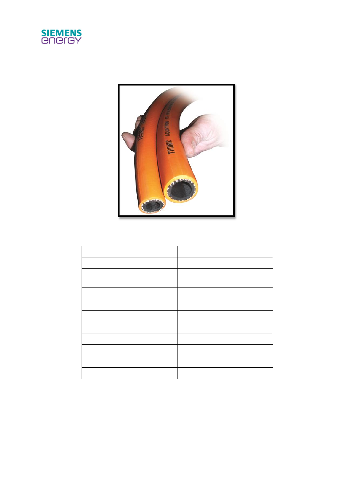
5.2 Siemens Energy AquaTRON pressure-balanced oil-filled hose
specification
Figure 8 AquaTRON hose, size 50 (1/2” bore), and size 75 (3/4” bore)
Hose type
AquaTRON 50
Diameter
Ø50mm OD, ½” bore
Min bend radius (static and
dynamic)
125mm (4.9”)
Maximum axial load
5,000N (1,121 lb)
Maximum twisting
180° per 5m (16.4ft) length
Mass (air)
0.66kg/m (0.44lb/ft)
Mass (water)
0.14kg/m (0.09lb/ft)
Max water depth
4,000m (13,123ft)
Oil fill pressure
15 bar (218 psi)
Filling Medium
Dow Corning 200 Silicone Oil
Deployment rate
350m/min (1149ft/min)
Table 5 AquaTRON oil-filled hose specification
This manual suits for next models
2
Table of contents
Other Siemens Energy Cables And Connectors manuals


