6/21
Building Technologies Division Mounting Instructions AGU2.522... CC1J7215en
Industry Sector Safety notes 11.05.2011
3 Safety notes
To avoid injury to persons, damage to property or the environment, the following
warning notes must be observed!
Warning!
Do not interfere with or modify the product!
Siemens will not assume liability for damage resulting from unauthorized interference!
3.1 Product liability
•All activities (mounting, installation, service work, etc.) must be performed by quali-
fied personnel
•Before performing any work in the connection area, disconnect the product from
mains supply (all-polar disconnection). Ensure that the plant cannot be inadver-
tently switched on again and that it is indeed dead. If not disconnected, there is a
risk of electric shock
•Ensure protection against electric shock by providing adequate protection for the
connection terminals
•Fall or shock can adversely affect the safety functions. Such products must not be
put into operation, even if they do not exhibit any damage
•After any kind of activity (mounting, installation, service work, etc.), check to ensure
that wiring is in an orderly state and that all safety functions are performed correctly
•Do not touch the 3 pins since they can cause injury
•To ensure ESD, wear an ESD wrist strap
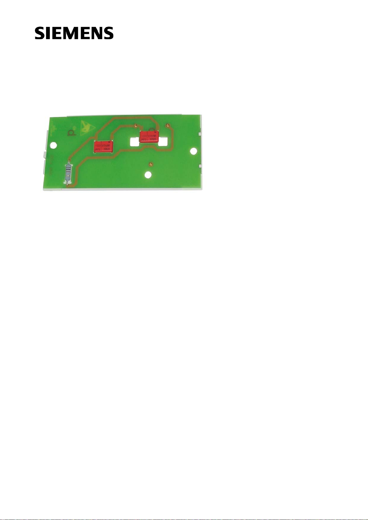
•Do not install the extra PCB in boilers equipped with LMU75...
Siemens will not assume liability for damage resulting from unauthorized inter-
ference!
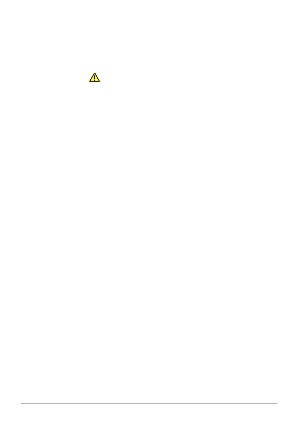
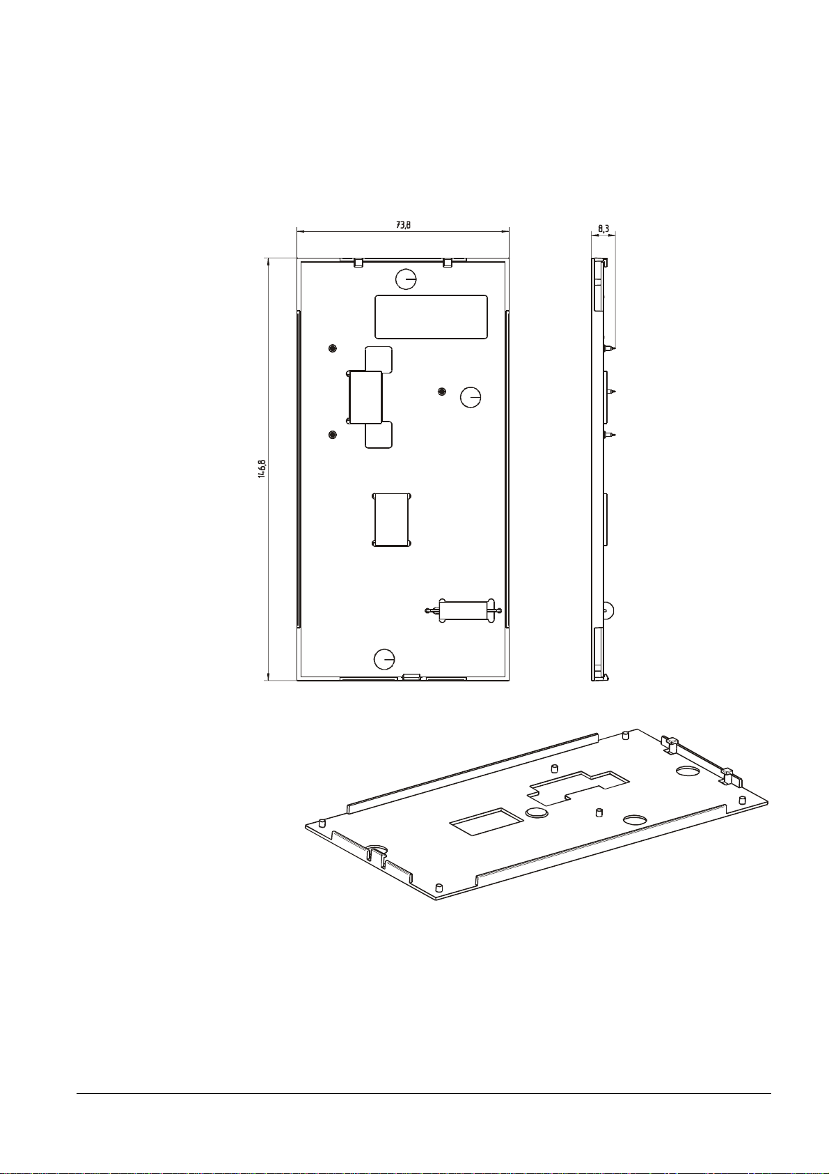
3.2 Mounting notes
Ensure the relevant national safety regulations are complied with.