FTV110/110C NG-LP Conversion Instructions 3
4. Ensure the combustion fan post-purges for at least 5 seconds prior to reactivating the igniter.
5. Set the thermostat to the lowest setting and continue with the Gas Valve and Burner Setup procedure outlined
below.
Combustion Calibration Procedure
To calibrate burner combustion, perform the following procedure using a calibrated combustion analyzer capable of
measuring CO2and CO from a Natural Gas or Propane burning appliance:
1. Set analyzer to the appropriate fuel (Propane).
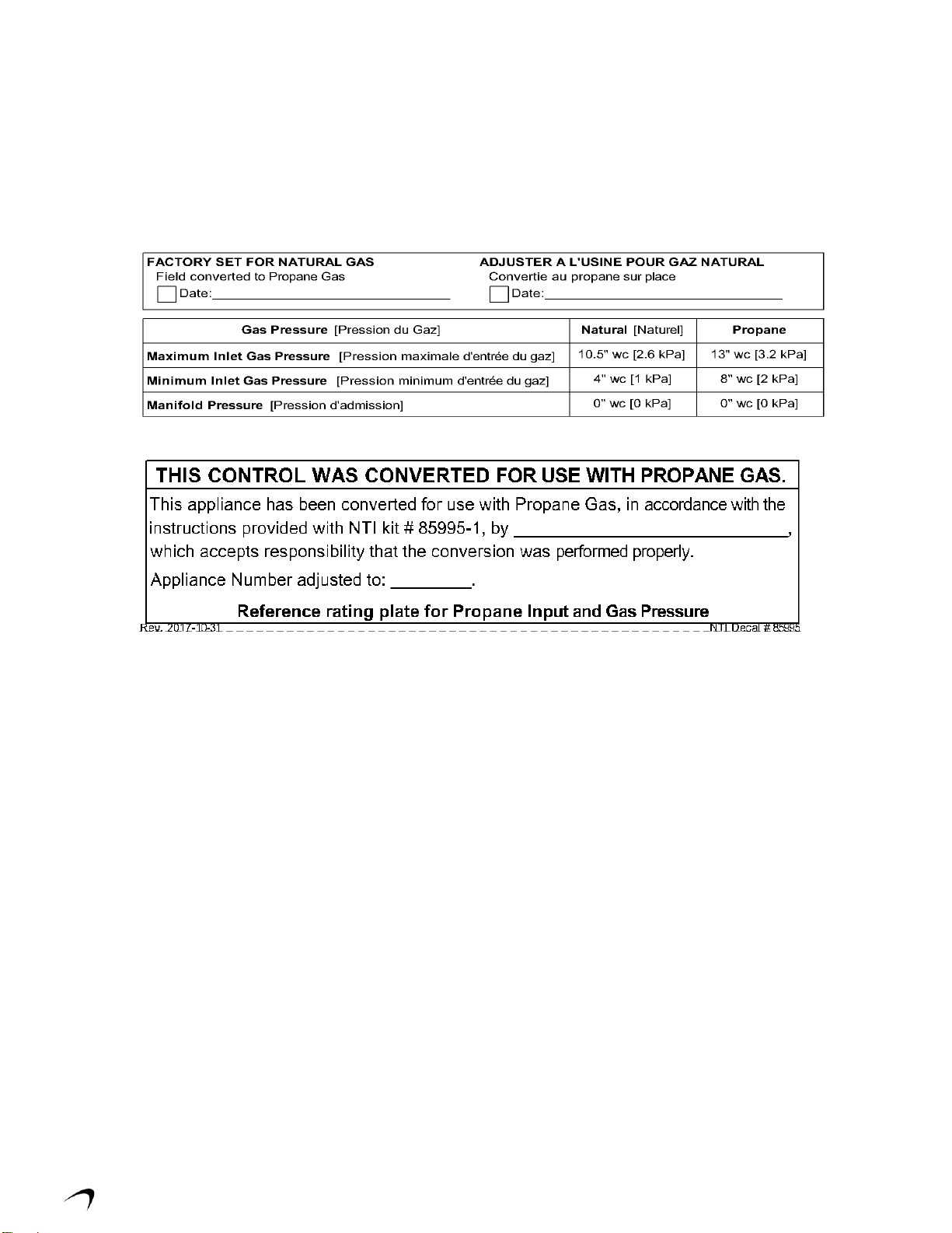
2. Gas Line Pressure Test –monitor gas line pressure throughout all combustion tests and verify it is maintained
within tolerance. See Gas Line Pressure Test below.
3. Set Throttle Screw –operate burner to the maximum modulation rate (see Table 2-2); set combustion according
to Table 1-1 using the Throttle Screw; allow time for the analyzer readings to stabilize between adjustments –
record CO2value. See Throttle Screw Adjustment below.
4. Set Offset Screw –operate burner to the minimum modulation rate (see Table 2-2); using the Offset Screw, set
the CO2to 0.4-0.8% lower than the value obtained during the maximum modulation rate test (e.g. if CO2at Max
= 10.5%, then CO2at Min must = 9.7-10.1%). See Offset Screw Adjustment below.
Combustion Calibration is mandatory upon installation and during each annual service.
Failure to perform the Combustion Calibration in accordance with these instructions may
result in incorrect combustion leading to burner damage or excessive Carbon Monoxide
concentrations causing property damage, personal injury or death.
Carbon Monoxide - Never leave the unit operating while producing Carbon Monoxide (CO)
concentrations in excess of 175 ppm. Failure to follow this warning may result in serious
injury or death.
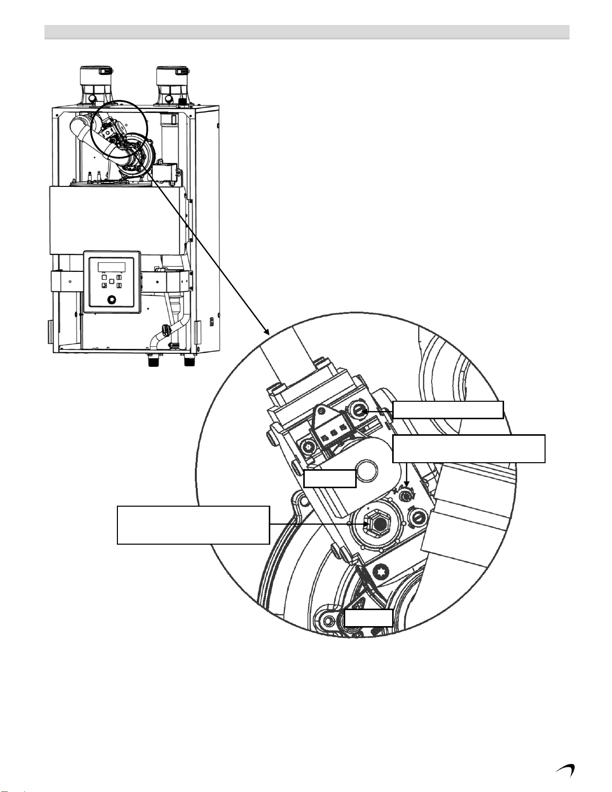
Throttle Screw Adjustment
The gas valve Throttle Screw (see Figure 2-1) is used to calibrate the CO2concentration with the burner operating at
or near the maximum modulation rate (see Table 2-2). Turning the Throttle Screw in (clockwise) decreases the CO2
concentration. Turning the Throttle Screw out (counterclockwise) increases the CO2 concentration. Typical
adjustment required is 0 –1/2of a turn in or out from the position established in Section 1.0 above.
NOTE: Calibration of the Throttle Screw should only be performed with the burner operating at or near the
maximum modulation rate (see Table 2-2).
Adjustments to the Throttle Screw may only be made by a qualified gas technician using a
calibrated combustion analyzer capable of measuring CO2and CO. Adjustments may only be
performed if the gas line pressure is maintained above minimum levels throughout the
duration of the test (see Table 2-1). Failure to follow these instructions may result in serious
injury or death.
Offset Screw Adjustment
The gas valve Offset Screw (see Figure 2-1) is used to calibrate the CO2offset at minimum modulation vs. maximum
modulation. Turning the Offset Screw in (clockwise) increases the CO2 concentration at minimum modulation rate.
Turning the Offset Screw out (counterclockwise) decreases the CO2 concentration at minimum modulation rate.
Typical adjustment required is 0 - 1/8th of a turn in or out from the factory setting.
NOTE: Calibration of the Offset Screw must only be performed with the burner operating at the minimum
modulation rate (see Table 2-2).
Adjustments to the Offset Screw may only be made by a qualified gas technician using a
calibrated combustion analyzer capable of measuring CO2and CO, and only with the burner
at the minimum modulation rate (see Table 2-2). Attempting to set the Offset Screw while the
burner is operating at a modulation rate other than the minimum will result in incorrect
combustion and may lead to burner damage or excessive CO.