PAW HeatBloC K36 User manual

1
General information
2 993203x3x-mub-en – V10 2018/02
Contents
1
General information .................................................................................................................. 3
1.1 Scope of these instructions .................................................................................................3
1.2 Designated use ...................................................................................................................3
2
Safety instructions .................................................................................................................... 4
3
Product description ................................................................................................................... 5
3.1 Equipment ...........................................................................................................................5
3.2 Function...............................................................................................................................6
3.3 Thermal control valve..........................................................................................................7
3.4 Ball valve with check valve..................................................................................................9
4
Assembly and installation [specialist] .......................................................................................10
4.1 Installation of the HeatBloC and commissioning...............................................................10
4.2 Accessories: compression fitting (not included in the scope of delivery) ..........................12
5
Deinstallation ...........................................................................................................................12
6
Scope of delivery [specialist]....................................................................................................13
7
Technical data .........................................................................................................................14
7.1 Pressure drop and pump characteristics...........................................................................15
Item no. 993203x3x-mub-en – Version V10 – Issued 2018/02
We reserve the right to make technical changes without notice!
Printed in Germany – Copyright by PAW GmbH & Co. KG
PAW GmbH & Co. KG
Böcklerstr. 11
D-31789 Hameln, Germany

1
General information
2018/02 993203x3x-mub-en – V10 3
1
General information
Carefully read these instructions before installation and commissioning.
Save these instructions in the vicinity of the installation for future reference.
1.1
Scope of these instructions
These instructions describe the function, installation, commissioning and operation of the
HeatBloC K36. For other components of the installation, such as pumps, controllers or the
distribution manifold, see the instructions of the corresponding manufacturer.
The chapters called [specialist] are intended for specialists only.
1.2
Designated use
The HeatBloC may only be used in heating circuits taking into consideration
the technical limit values indicated in these instructions.
The HeatBloC must
not
be used in drinking water applications.
Improper usage excludes any liability claims.
Only use PAW accessories with the HeatBloC.
The wrapping materials are made of recyclable materials and can be disposed of
with recyclable materials.

2
Safety instructions
4 993203x3x-mub-en – V10 2018/02
2
Safety instructions
The installation and commissioning as well as the connection of electrical components require
technical knowledge commensurate with a recognised vocational qualification as a fitter for
plumbing, heating and air conditioning technology, or a profession requiring a comparable
level of knowledge [specialist].
The following must be observed during installation and commissioning:
•Relevant local and national prescriptions
•Accident prevention regulations of the professional association
•Instructions and safety instructions mentioned in this manual
CAUTION
Personal injury and damage to property!
The HeatBloC must only be used in heating circuits filled with
heating water according to VDI 2035 / Ö-Norm H 5195-1.
The HeatBloC must
not
be used in drinking water applications.
NOTICE
Material damage due to mineral oils!
Mineral oil products cause lasting damage to seals made of EPDM, whereby the sealant
properties get lost. We do not assume liability nor provide warranty for damage to property
resulting from sealants damaged in this way.
It is imperative to avoid that EPDM gets in contact with substances containing
mineral oils.
Use a lubricant based on silicone or polyalkylene and free of mineral oils, such as
Unisilikon L250L and Syntheso Glep 1 of the Klüber company or a silicone spray.

3
Product description
2018/02 993203x3x-mub-en – V10 5
3
Product description
The HeatBloC K36 is a preassembled group of fittings for heating circuits.
The HeatBloC is mounted directly to the wall with the enclosed wall bracket.
3.1
Equipment
A-1 Return to the boiler
A-2 Full metal thermometer integrated
in the ball valve (return, blue)
B Heating pump
C Thermal control valve
D-1 Return from the buffer tank
E-1 Flow to the buffer tank
E-2 Ball valve with check valve
F Flow tube
G-2 Full metal thermometer integrated
in the ball valve (flow, red)
G-1 Flow from the boiler

3
Product description
6 993203x3x-mub-en – V10 2018/02
3.2
Function
K36 boiler charging set for return flow temperature maintenance
of solid fuel boilers, wood firing and stove heating systems
The boiler charging set prevents the temperature in the boiler
from falling under the dew point, thus reducing the contamination
of the boiler.
Application ranges:
•The boiler charging set is connected to a buffer tank.
When the opening temperature of 50 °C or 60 °C
is reached in the boiler circuit, the pump can charge the
buffer tank.
Buffer tank
Solid
fuel boiler

3
Product description
2018/02 993203x3x-mub-en – V10 7
3.3
Thermal control valve
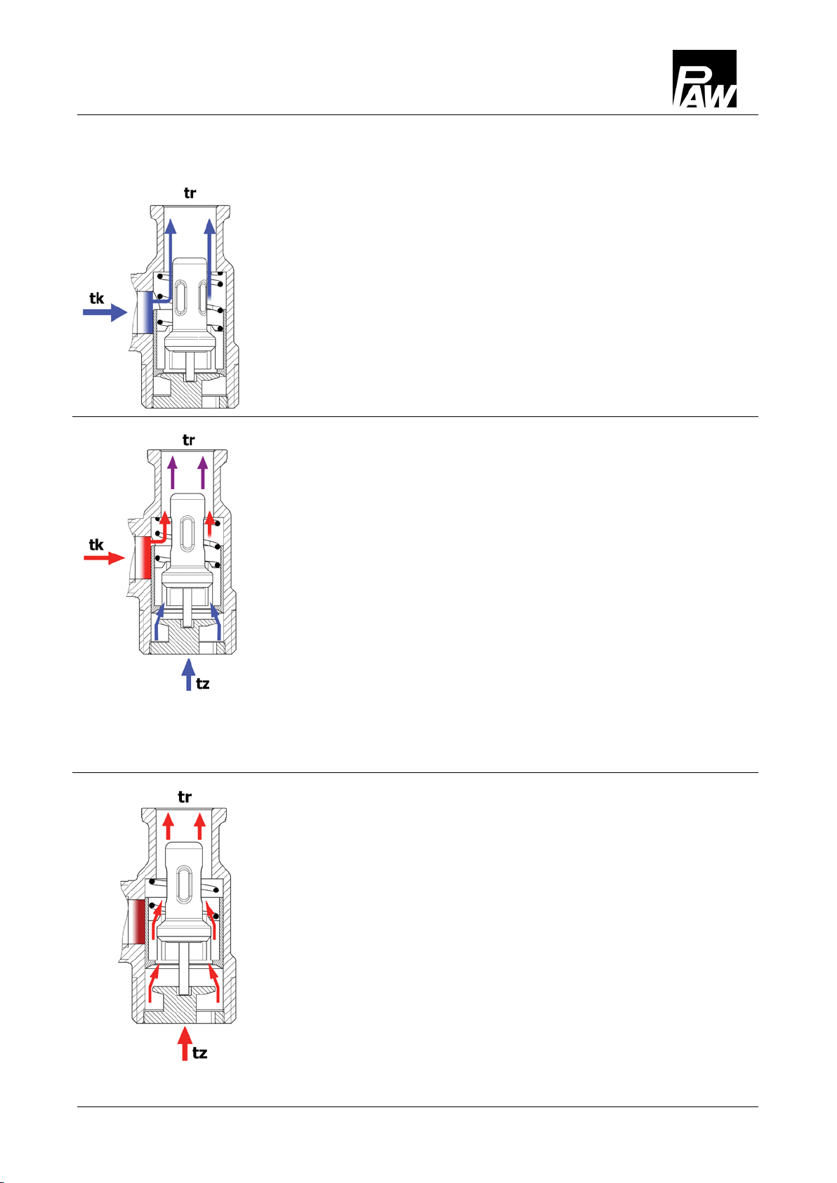
The thermal valve shuts off the connection to the tank, as long
as the water in the boiler circuit [tk] is colder than the opening
temperature of the thermal control valve. The pump in the K36
circulates the water in the boiler circuit through the automatic
bypass which is completely open.
When the water in the boiler circuit [tk] has obtained the opening
temperature (+/- 3 K) of the thermal control valve, the valve opens
the connection from/to the tank. The bypass shuts off to the same
extent as the connection to the tank is opened. The control valve
opens the return line from the tank and thus enables the water to
circulate in the tank circuit. The cold water from the tank return line
is mixed in the control valve with the hot water from the bypass.
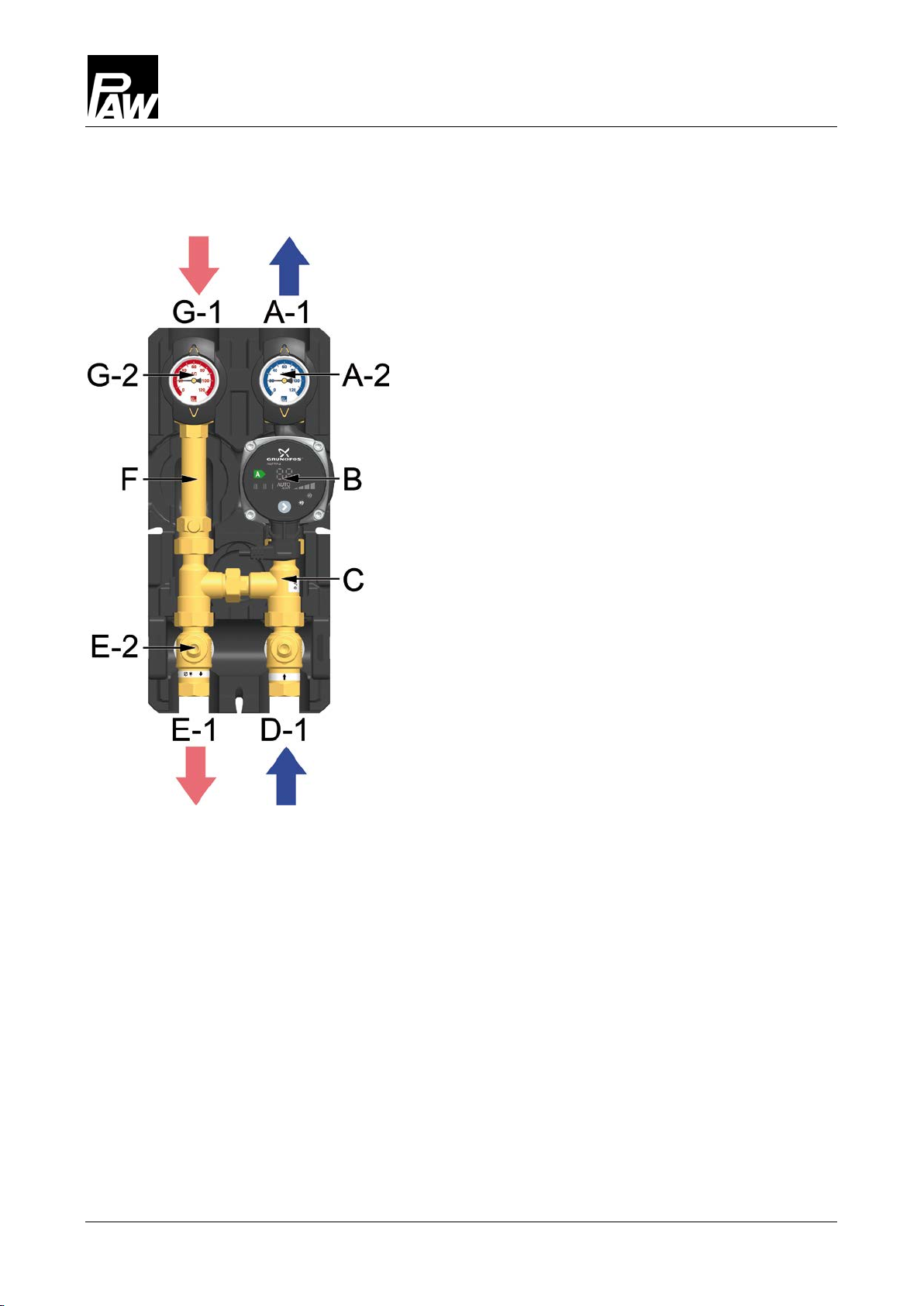
Depending on the temperature and the flow rate of the water from
the return line the thermal control valve shuts off or opens the line
to the tank. Thus the return line which leads to the boiler [tr] always
remains at a certain temperature level.
With rising temperature in the flow line of the boiler or with rising
temperature from the return line of the tank [tz] the thermal control
valve opens the connection to the tank. The temperature of the
return line of the boiler remains nearly constant (+/- 3 K).
Please note:
When the boiler output is controlled by the boiler temperature the
boiler must heat up 20 K above the opening temperature of the
K36. Otherwise there will not be enough power available (the
boiler output may be reduced before the thermal control valve
opens completely).

3
Product description
8 993203x3x-mub-en – V10 2018/02
Change of the flow line [specialist]
1. Take off the thermometer handles (A-2, G-2)
and remove the insulating front shells.
2. Take the HeatBloC out of the insulating
back shell.
3. Unscrew the union nuts of the thermal
control valve (C).
Modification and commissioning of the HeatBloC
1. Interchange the flow line with the return
line, the thermal control valve (C) and the
pump (B).
Consider the direction of flow!
Turn the pump head such that the terminal
head is directed to the top or to the centre of
the HeatBloC.
2. Interchange the lower ball valves so that the
ball valve with integrated check valve (E-2)
is mounted in the flow line.
3. Mount the HeatBloC and connect it to the
installation.
4. Check all union nuts before commissioning
and firmly tighten them if necessary.
Mount the insulation after the pressure test.
Mount the thermometer handles (A-2, G-2).

3
Product description
2018/02 993203x3x-mub-en – V10 9
3.4
Ball valve with check valve
The HeatBloC is equipped with a ball valve with integrated check valve (E-2) in the flow line.
During operation, the check valve must be closed (position 0°).
For filling, draining and venting, the check valve must be opened manually. Therefore, turn the
ball valve to the position 45°.
0°
45°
90°
Check valve is operating,
flow only in flow direction.
Check valve is not operating,
flow in both directions.
Ball valve closed,
no flow.

4
Assembly and installation [specialist]
10 993203x3x-mub-en – V10 2018/02
4
Assembly and installation [specialist]
NOTICE
Damage to property!
The location of installation must be dry, load-carrying, frost-proof and protected against
ultraviolet radiation to prevent material damage to the installation.
4.1
Installation of the HeatBloC and commissioning
The HeatBloC K36 is mounted directly to the wall with the enclosed wall bracket.
Solid fuel boiler
Flow
Return
Flow
Return
Buffer tank

4
Assembly and installation [specialist]
2018/02 993203x3x-mub-en – V10 11
1. Fix the wall bracket to the wall with
appropriate screws and washers.
2. Take off the thermometer handles
(A-2, G-2) and take the group of
fittings out of the insulation.
3. Push the insulating back shell
onto the wall bracket.
4. Insert the clip springs in the lower
ball valves.
5. Push the group of fittings onto the
wall bracket.
6. Connect the group of fittings to the
system by pipework. The installation
to the piping must be carried out
without any tension.
7. Connect the pump.
8. Carry out the pressure test and
check all thread connections.
9. Mount the insulating front shells and
the thermometer handles (A-2, G-2).

5
Deinstallation
12 993203x3x-mub-en – V10 2018/02
4.2
Accessories: compression fitting (not included in the scope of delivery)
The connection to the heating installation can be carried out fast, pressure-proof and without
soldering when you use the optionally available compression fittings.
Not included in
the scope of delivery!
1. Push the union nut ② and the cutting ring ③ onto the
copper pipe ①. The pipe must protrude at least 3 mm
from the cutting ring in order to ensure the force
transmission and the sealing.
2. Insert the support sleeve ④ into the copper pipe.
3. Insert the copper pipe with the plugged-on individual
parts (②, ③ and ④) all the way into the housing of
the compression fitting ⑤.
4. First screw the union nut ② manually.
5. Tighten the union nut ② by rotating one full turn.
Secure the housing of the compression fitting ⑤
against distort in order to avoid damaging the
sealing ring.
5
Deinstallation
To remove the boiler charging set from the
mounting plate, push the clips sidewards with
a screwdriver. The boiler charging set can then
be pulled forwards (consider the tubing!).

6
Scope of delivery [specialist]
2018/02 993203x3x-mub-en – V10 13
6
Scope of delivery [specialist]
NOTICE
Complaints and requests/orders of spare parts will only be processed with information on the
serial number! The serial number is placed on the return pipe of the heating circuit.
Accessories
Item number
Cartridge for thermal control valve, for opening temperature 50 °C G3809
Cartridge for thermal control valve, for opening temperature 60 °C G3810
Pump
Item number
Wilo-Yonos PARA RS 15/6 E1236036
Wilo-Stratos PICO 15/1-6 E1239615
Grundfos UPM3 Auto L 15-70 PP3 E1212360
Grundfos Alpha2.1 15-60 E121221

7
Technical data
14 993203x3x-mub-en – V10 2018/02
7
Technical data
K36
DN 20 (¾")
Dimensions
Centre distance (1) 90 mm
Width insulation (2) 180 mm
Height insulation (3) 385 mm
Installation length (4) 347 mm
Connections ¾" internal thread
Technical data
Opening pressure check valve (E-2) 200 mm wc, can be opened
Opening temperature 50 °C / 60 °C
Materials
Valves and fittings Brass
Gaskets EPDM/NBR
Insulation EPP

7
Technical data
2018/02 993203x3x-mub-en – V10 15
K36
DN 20 (¾")
Hydraulics
Maximum pressure 6 bars
Maximum temperature 110 °C
KVS value [m3/h] 2.5
7.1
Pressure drop and pump characteristics
Pressure [m wc]
Pressure [kPa]
Flow rate [l/h]

PAW GmbH & Co. KG
Böcklerstraße 11
D-31789 Hameln, Germany
www.paw.eu
Phone: +49 (0) 5151 9856 - 0
Fax: +49 (0) 5151 9856 - 98
993203x3x-mub-en – V10 2018/02
Table of contents
Popular Boiler Supplies manuals by other brands

JJM Boiler Works
JJM Boiler Works NB Series Installation operation & maintenance

Fröling
Fröling RS4 Installation and operating instructions

Daalderop
Daalderop Combi Assembly instructions

Viessmann
Viessmann ESS VITOBLOC 200 Installation & Operating Instructions For Contractors

STIEBEL ELTRON
STIEBEL ELTRON KV 30 Operation and installation