Xylem McDonnell & Miller 47 Series User manual

INSTRUCTION MANUAL
Series 47 and 247
Mechanical Water Feeders
Series 47-2 and 247-2
Combination Mechanical
Water Feeder/Low Water
Cut-Off
For steam and hot water boilers with cold
water feed, to maintain a minimum safe
water level independent of electrical service.
Series 47
Water Feeder
Applications:
• Before using this product read and understand instructions.
• Save these instructions for future reference.
• All work must be performed by qualified personnel trained in the proper application, instal-
lation, and maintenance of plumbing, steam, and electrical equipment and/or systems in
accordance with all applicable codes and ordinances.
• To prevent serious burns, the boiler must be cooled to 80˚F (27˚C) and the pressure must be
0 psi (0 bar) before servicing.
• To prevent electrical shock, turn off the electrical power before making electrical connections.
• The low water cut-off switch must be installed in series with all other limit and operating
controls installed on the boiler. After installation, check for proper operation of all of the
limit and operating controls, before leaving the site.
• We recommend that secondary (redundant) Low Water Cut-Off controls be installed on all
steam boilers with heat input greater than 400,000 BTU/hour or operating above 15 psi
steam pressure. At least two controls should be connected in series with the burner
control circuit to provide safety redundancy protection should the boiler experience a
low-water condition. Moreover, at each annual outage, the low water cutoffs should be
dismantled, inspected, cleaned, and checked for proper calibration and performance.
• Boiler manufacturer schematics should always be followed. In the event that the boiler
manufacturer's schematic does not exist, or is not available from the boiler manufacturer,
refer to the schematics provided in this document.
• To prevent a fire, do not use this low water cut-off to switch currents over 10.2A, 1/2 HP at
120 VAC or 5.1A, 1/2 HP at 240 VAC, unless a starter or relay is used in conjunction with it.
WARNING CAUTION
!
WARNING
Series 47-2 Combination
Water Feeder Low Water
Cut-Off
Series 247
Water Feeder
Series 247-2 Combination
Water Feeder Low Water
Cut-Off
MM-316E
California Proposition 65 warning! This product contains chemicals known to the
•
state of California to cause cancer and birth defects or other reproductive harm.
Previous controls should never be installed on a new system. Always install new
•
controls on a new boiler or system.
!

Water Feeder
Closing Level
Low
Water Cut-Off
Burner Starts
21/4" (57mm)
37
/16" (87mm)
23/4" (70mm)
Feeder keeps water
level 37/16" (87mm)
above center of lower
gauge glass tapping
If extreme priming or
foaming causes water
line to fall 13/16" (30mm)
below feeder closing
level, cut-off switch
stops the burner
When water level is
restored 1/2" (13mm)
above emergency.
Cut-off switch starts
burner and the water
feeder resumes
control
Motor Switch Rating (Amperes)
Voltage Full Load Locked Rotor Pilot Duty
120 VAC 10.2 61.2 125 VA at 120
240 VAC 5.1 30.6 or 240 VAC, 60 Hz
OPERATION
Series 47/47-2 Operating Levels
All Models
• Maximum Water Pressure: 150 psi (10.5 kg/cm2)
• Maximum Water Temp: 120˚F (49˚C)
• Water Connection Size: 1
/2” NPT
47/47-2
• Maximum Boiler Pressure: 25 psi (1.76 kg/cm2)
247/247-2
• Maximum Boiler Pressure: 30 psi (2.1 kg/cm2)
Electrical Ratings
Series 47 Water Feeders and Series 47-2
Combination Water Feeder/Low Water Cut-Off
maintain minimum water level in the boiler during
normal operation.
Series 47-2 Combination Water Feeder/Low
Water Cut-Off allows the burner to operate on
demand as the water level is restored to its
proper level.
Series 47-2 Combination Water Feeder/Low
Water Cut-Off shuts off the burner if the boiler
water level drops 1 3/16” (30mm) below the water
feeder’s closing level.
2
CAUTION:
A more frequent replacement interval may be necessary based on the condition of
the unit at time of inspection. McDonnell Miller s warranty is one (1) year from date
of installation or two (2) years from the date of manufacture.
Failure to follow this warning could cause property damage, personal inj ury or death.
&'

;;
;;
;;
117/8"
;
;
;
;
;
;
PARALLEL TO BOILER
OUT IN
117/8"
105/8"
OUT
IN
;;
;;
;;
;;
;;
;;
(alternate water equalizing tapping used)
OUT
IN
105/8"
135/8"
9"
9"
135/8"
;;
;;
;;
(alternate water equalizing tapping used)
IN OUT
105/8"
RIGHT ANGLED TO BOILER
WITH TURNED Y FITTINGS
PARALLEL TO BOILER
WITH TURNED Y FITTINGS
3
STEP 1 - Determine Best Position to Install the Water Feeder
(to clear obstructions that may be encountered on the side of the boiler).
INSTALLATION –
TOOLS NEEDED:
Two (2) pipe wrenches, and one (1) flathead screwdriver.
Series 247 and 247-2 Operating Level
Valve Off -7/16" (11.1mm)
Casting Line - 0"
Burner On - 1/4" (6.4mm)
Burner Off - 3/4" (19mm)
Water feeder figures are +/- 1/4" (6.4mm)
Burner figures are +/- 1/8" (3.2mm)
TOP VIEWS

E
F
D
10-5/8"
(270mm)
G
d. Determine the position of the black "Y" casting (F).
If gauge glass tappings (D) and (E) are less
than 10 5⁄8" (270 mm) apart, install the black
"Y" casting (F) as depicted in the diagram to the
top right.
OR
If gauge glass tappings (D) and (E) are
greater than 10 5⁄8" (270 mm) apart, invert
the black "Y" casting (F) as depicted in the
diagram to the bottom right.
OR
If gauge glass tappings (D) and (E) are
greater than 14" (356 mm) apart, invert the
black "Y" casting (F) as depicted in the diagram
to the bottom right and install a longer nipple (G).
F
INVERTED “Y” CASTING
Note:
Reverse union
nuts, packing
and plug.
Tighten top
nut securely.
G
4
STEP 2 - Preparation (Installing Quick Hook-up Fittings to Water Feeder)
a. Turn the boiler off.
A
b. Drain the water in the boiler until the level falls below the lower
gauge glass connection (A). Allow the boiler to cool to 80˚F
(27 ˚C) and allow the pressure to release to 0 psi (0 bar).
B
C
c. Remove the water glass (B) and gauge glass connections (C)
from the boiler.
OFF
ON

F
G
g. Slide the black "Y" (F) casting over the nipple (G)
in accordance with Step 2d, but do not tighten.
L
F
M
NL
P
U
UK
Q
Q
h. 1). Apply sealant to the external threads of the nipple (L)
of the upper "Y" connection. Using a pipe wrench,
tighten the nipple (L) into the 1/2" (15 mm) NPT
tapping (M) of the black "Y" casting (F). Slide union
nut (U) over nipple (L). Using a pipe wrench tighten
the upper “Y” connection (N) to nipple (L). Tighten to
54 ft•lb (74 N•m).
2). Apply sealant to the external threads of the tailpiece (P)
of the lower "Y" connection. Slide union nut (U) over
tailpiece (P). Using a pipe wrench, tighten the tailpiece
(P) into the 1/2” (15 mm) NPT tapping (Q) in the lower
half of body (K). Tighten to 54 ft•lb (74 N•m).
5
J
H
K
e. Remove the plug (H) from the 1/2" (15 mm) NPT
tapping (J) in the top of the feeder body (K).
J
G
K
No Threads
f. Apply thread sealant to the external threads. Using
a pipe wrench, tighten the 1/2" (15 mm) NPT nipple
(G) into the tapping (J) on the top of the feeder (K)
to approximately 54 ft•lb (74 N•m).
Note: Nipple (G) is only threaded on one end.
Upper “Y”
Lower “Y”
When using pipe or tape sealant on the external threads of pipes or fittings, follow the manufacturers
instructions. Use sparingly and do not place on the first thread.
!
IMPORTANT

6
STEP 3 - Installing Series 47 Water Feeder or Series 47-2 Combination Water
Feeder/Low Water Cut-Off with Quick Hook-Up Fittings to Boiler
a. Apply thread sealant to the external threads
of the "Y" fittings (T). Using the pipe wrench,
install them in the boiler gauge glass tappings (S),
and tighten to approximately 54 ft•lb (74 N•m).
Tighten both union nuts (U).
b. Reinstall water glass and gauge connections to “Y”
fittings (T).
When using pipe or tape sealant on the external threads of pipes or fittings, follow the manufacturers
instructions. Use sparingly and do not place on the first thread.
!
IMPORTANT
U
N
L
U
U
T
S
R
i. Using the pipe wrench, tighten the furnished pipe
plug into the open tapping (R) on the lower half of
the feeder float body in accordance with the
position diagrams in Step 1. Tighten the plug to
approximately 20 ft•lb (27.3 N•m).

STEP 4 - Installing Series 247/247-2 Water Feeder to Boiler
Burner Boiler
City Water Supply
Return
Header
Series 247
Water
Feeder
Casting
Line ByPass
Valve
Pipe the Series 247/247-2 water feeder so that
the line on the casting is 3" (76mm) above the
minimum safe operating level as specified by
the boiler manufacturer.
Recommended Piping
STEP 5 - Piping the valve on the Models 47/47-2 and 247/247-2
TO BOILER
By-Pass
Valve
Swing Check
STEP 6 - Electrical Wiring (Only for Series 47-2 & 247-2)
AA
a. Using the flathead screwdriver, loosen the two
(2) screws that secure the switch cover (AA).
Remove cover.
7
!
IMPORTANT
Boiler manufacturer schematics should always be followed. In the event that the boiler manufacturer's schematic
does not exist, or is not available from the boiler manufacturer, refer to the schematics provided in this document.
a. Follow the drawing to the right for piping the valve
to the boiler and city water supply. When piping the
valve, remember to leave room for servicing the
valve.
b. Piping the valve this way will aid in troubleshooting
the valve and piping in the future.

8
STEP 7 - Testing and Inspection
V
CLOSING
LEVEL
INSTALLATION COMPLETE
C.
Line
Load
N.
N.C.
O.
C.
Load
or
Burner
Circuit
Low
Water
Alarm
N.
N.C.
Neutral
120 V.A.C.
or 24 V.A.C.
Supply
HOT O.
b. Based on the mode of operation required for
your application, complete the appropriate
corresponding step.
When the water feeder is used as a low water
cut-off switch and/or a low water alarm
, connect
the "Hot" wire to the "Common" contact. Using a
flat head screw driver, tighten the screw. Connect
the low water alarm to the “Normally Open” contact
and tighten the screw. Connect the burner or load
circuit wire to the “Normally Closed” contact and
tighten the screw.
OR
When the water feeder is used as a pilot switch
to a holding coil of a motor starter or relay,
connect as shown in the diagram to the right.
Low water cut-off switch and/or low water alarm
Pilot switch for motor starter or relay
The feeder should be blown down after initial installation
before leaving site. It should also be blown down as
recommended in the Maintenance section of these
instructions.
• Burner should be on and water level above 'closing
level' of feeder.
•Slowly open the water feeder blow down valve 'V'
which will lower the water level in the float chamber.
As water flows out the blow down pipe, you should
begin to hear the feeder valve open.
• If the feeder has a #2 switch, the burner should stop.
• Close the water feeder blow down valve 'V'. The water
level should return to a safe operating level and the
burner should turn on.
To prevent serious personal injury from steam pipe
blow down, connect a drain pipe to the control
opening to avoid exposure to steam discharge.
Failure to follow this caution could cause personal
injury.
!
CAUTION
Blow Down of Feeder

9
X
Z
TO BOILER
Feed
Valve By-Pass
Valve
Check Valve
WATER
SUPPLY
Make sure that the water level in the boiler is above the
closing level of the feeder.
Close valve 'X' and slowly open union 'Z' to determine if
valve is leaking.
• If water is leaking from the union, the valve needs to
be serviced.
• If no water leaks from the union, the feeder operation
is not the cause of the flooding.
Broken Union Test
E
D
B
H
x 4
A. Using a 1/2" socket wrench, unscrew the four (4) hex-head
bolts (B) that secure the strainer basket (H) to the valve
assembly (E).
B. Using a 13/16" socket wrench, unscrew the cartridge (D)
and remove.
C. Clean any debris (scale, rust, etc.) from strainer and cartridge.
Poppet inside cartridge must move freely. Replace if debris
cannot be removed or poppet does not move freely.
D. Lubricate cartridge o-rings using silicone type lubricant and
re-install.
E. Re-install strainer basket.
Removal of cartridge and strainer for inspection and cleaning

10
TROUBLESHOOTING
The following is intended as a guide to determine why the feeder may not be operating as intended. Please note that
there can be system and installation issues that can affect the operation of the feeder. This includes but is not limited to
the following:
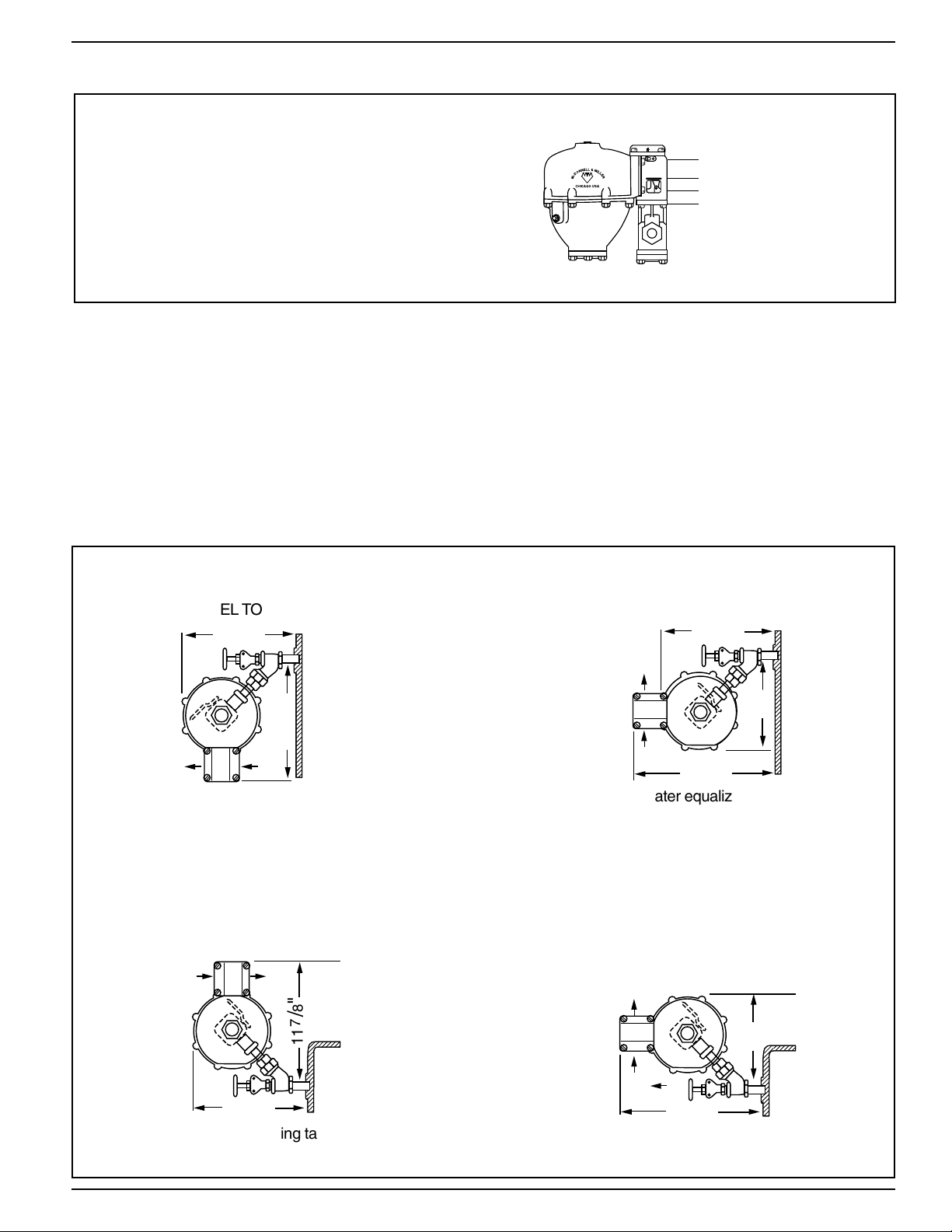
• Piping not installed properly • Priming and foaming of boiler water
• Faulty check valve in return header • Delay in condensate returning to boiler
• Tankless coil leaking
Boiler is getting too much water.
a) Cause: There is something preventing the valve
(cartridge poppet) from completely closing.
Test: Perform broken union test.
Solution: Remove and inspect cartridge. Clean or
replace as necessary.
b) Cause: By-pass valve is leaking.
Test: Perform broken union test.
Solution: Repair or replace valve.
c) Cause: Float chamber clogged with sediment.
Test: Open blow-down valve. If there is little or no
water flow, the chamber may be clogged with sediment.
Solution: Remove bottom of float chamber. Clean
sediment from chamber, float and bellows mechanism.
Replace control if necessary.
d) Cause: Float has filled with water.
Solution: Replace float.
e) Cause: Equalizing piping is plugged.
Solution: Clean or replace piping.
f) Cause: Water supply is above 150 psi.
Solution: Install pressure reducing valve to reduce
water pressure.
Boiler is not getting enough water.
a) Cause: There is something preventing the valve
(cartridge poppet) from fully opening.
Test: Perform broken union test.
Solution: Remove and inspect cartridge. Clean or
replace as necessary.
b) Cause: Strainer clogged with sediment.
Test: Perform broken union test.
Solution: Remove and inspect strainer. Clean or
replace as necessary.
c) Cause: Float chamber clogged with sediment.
Test: Open blow-down valve. If there is little or no
water flow, the chamber may be clogged with sediment.
Solution: Remove bottom of float chamber and clean
sediment from chamber, float and bellows mechanism.
Replace control if necessary.
d) Cause: Feed line between valve and boiler is partially
plugged.
Test: Perform broken union test. With union broken,
there should be water flowing through the piping from
the boiler.
Solution: Clean or replace piping.
e) Cause: Feed line between valve and city water supply
is plugged.
Solution: Clean or replace piping.
f) Cause: Water supply pressure is less than boiler
pressure.
Solution: Reduce boiler pressure or convert to pumped
return.

11
MAINTENANCE
SCHEDULE:
Weekly
• Blow down when boiler is in operation.
Annually
• Disassemble and inspect/clean strainer screen.
Replace if screen is torn or not able to be cleaned.
• Remove and inspect/clean cartridge. Replace if
poppet does not move freely or debris cannot be
removed.
• Remove lower float chamber and inspect internal
parts. Clean out all mud, silt, sediment and debris from
chamber, float mechanism and other waterside
components.
• Inspect equalizing piping. Clean or replace as
required.
• Check all wires for brittle or worn insulation.
• Check for leaks at gasket surfaces and solder joints.
Replace entire unit including equalizing piping every
10 years.
More frequent cleaning or replacement may be
required if used in locations where water treatment is
required or in applications with high make-up water
requirements.
NOTE
Use clean water to rinse components and surfaces. DO
NOT use sharp objects to scrape off any accumulations
of sediment or debris.
Unit is making noise.
a) Cause: Under certain system conditions, there may be
a vibration when the valve mechanism (cartridge poppet)
is slightly open.
Solution: Install a pressure reducing valve, such as the
Bell & Gossett B-38, in the inlet water line before the
feeder valve.
Burner switch not working.
a) Cause: Cam worn or broken.
Solution: Replace cam assembly (CO-106/302900).
b) Cause: Linkages not transferring float movement
to switch.
Solution:
• Linkage pins may be worn or broken which would
require purchasing a new valve assembly
(SA47-101-102/341600).
• Float may be damaged, sediment may have
accumulated in chamber or equalizing piping may be
plugged. Perform testing to determine what the
problem may be and correct.
Water leaking from bellows
a) Cause: Continuous exposure to chemicals or water with
pH higher than 9.0 can cause the solder to deteriorate.
Solution: Remove source of chemicals or consider
replacing control with one that is suitable for the
application.
TROUBLESHOOTING (cont'd)

Xylem Inc.
8200 N. Austin Avenue
Morton Grove, Illinois 60053
Phone: (847) 966-3700
Fax: (847) 965-8379
www.xyleminc.com/brands/mcdonnellmiller
McDonnell & Miller is a trademark of Xylem Inc. or one of its subsidiaries.
1) The tissue in plants that brings water upward from the roots;
2) a leading global water technology company.
We’re 12,000 people unified in a common purpose: creating innovative solutions
to meet our world’s water needs. Developing new technologies that will improve
the way water is used, conserved, and re-used in the future is central to our work.
We move, treat, analyze, and return water to the environment, and we help people
use water efficiently, in their homes, buildings, factories and farms. In more than
150 countries, we have strong, long-standing relationships with customers who
know us for our powerful combination of leading product brands and applications
expertise, backed by a legacy of innovation.
For more information on how Xylem can help you, go to www.xyleminc.com
Xylem
© 2013 Xylem Inc. MM-316E July 2013 Part No. 210386
This manual suits for next models
3
Table of contents
Other Xylem Boiler Supplies manuals