Siemens CC-5 User manual

SiemensSiemens
SiemensSiemens
Siemens IndustryIndustry
IndustryIndustry
Industry,,
,,
,Inc.Inc.
Inc.Inc.
Inc.
BuildingBuilding
BuildingBuilding
Building
TT
TT
Tecec
ecec
echnologies Dihnologies Di
hnologies Dihnologies Di
hnologies Divisionvision
visionvision
vision
P/N 315-033035-6
INTRODUCTION The Model CC-5 Cardcage from Siemens Industry, Inc., (see Figure 1) has five card
slots and occupies two positions on the studs in the backbox or on the optional CAB-
MP Mounting Plate. The Model CC-2 Cardcage (see Figure 2) has two card slots and
occupies one position on the studs in the backbox or on the optional CAB-MP
Mounting Plate. The CC-5 and CC-2 are used for mounting all system circuit card
assemblies. They each have two removable terminal block connectors at the top and
one removable terminal block connector at the bottom of each card slot. All field-
wiring connections are made directly to the top of the cardcage while internal power
is connected to the bottom of the cardcage. The two removable terminal block
connectors at the top of each slot are arranged in two rows. The lower row is labeled
1 through 8 and the upper row is labeled 9 through 16. These removable terminal
block connectors are used for connecting power limited external equipment.The
removable terminal block connector located at the bottom of each slot is labeled 17
through 24 and is used for connecting internal power.
Figure 1 Figure 2
CC-5 Card Cage CC-2 Card Cage
OPERATION The CC-5 and CC-2 provide a central point for mounting circuit card assemblies. If a
card requires power, it is applied through the removable terminal block at the bottom
of the cardcage. All external devices for the card are connected to the card through
the two removable terminal blocks at the top of the cardcage. The circuit card
assemblies are connected to the HNET and CAN bus through the connectors on the
cardcage.
Note:
Boards shown without card guides installed.
System Cardcage
Installation Instructions
Models CC-5 / CC-2

Siemens Industry, Inc.
Building Technologies Division
P/N 315-033035-62
PRE-INSTALLATION The CC-5 and CC-2 are shipped with the card guides removed.The card guides are
keyed to assist in installation.They can be installed either before or after the cardcage
is installed in the enclosure. For ease of installation, the card guides have been
designed to be installed after the field wiring has been completed.
Card Guide Installation (Figure 3)
The upper and lower card guides are keyed differently and are not interchangeable.
Ensure that the card guide keys fit easily into the holes in the motherboard to
prevent damage.
1. The upper card guide has a label on each slot that can be used to identify
the module installed in the slot. If desired, complete the label before
inserting the upper card guide.
2. Insert the upper card guide and secure with the captive screws.
3. Insert the lower card guide and secure with the captive screws.
GUIDE
PIN
GUIDE PIN HOLE
CAPTIVE SCREW RETAINERS
CAPTIVE SCREWS
LABELS
LOWER CARD GUIDE
UPPER CARD GUIDE
Figure 3
Card Guide Installation (CC-5 Shown)
INSTALLATION
Remove all system power before installation, first battery then AC. (To power up,
connect the AC first, then the battery.)
The CC-5 and CC-2 mount at the back of the enclosure of the FireFinder-XLS/Desigo
Fire Safety Modular/Cerberus PRO Modular system on the studs in the backbox or on
the optional Mounting Plate (CAB-MP).The Mounting Plate may be located either

Siemens Industry, Inc.
Building Technologies Division
P/N 315-033035-63
“IN” or “OUT” of the enclosure to perform this installation procedure. If the Mount-
ing Plate is located “IN” the enclosure you will have to gain access to it by opening
the enclosure Inner and Outer doors. If the Mounting Plate is located outside of the
enclosure, place it in front of you so that the word “TOP” is at the top and away from
you.
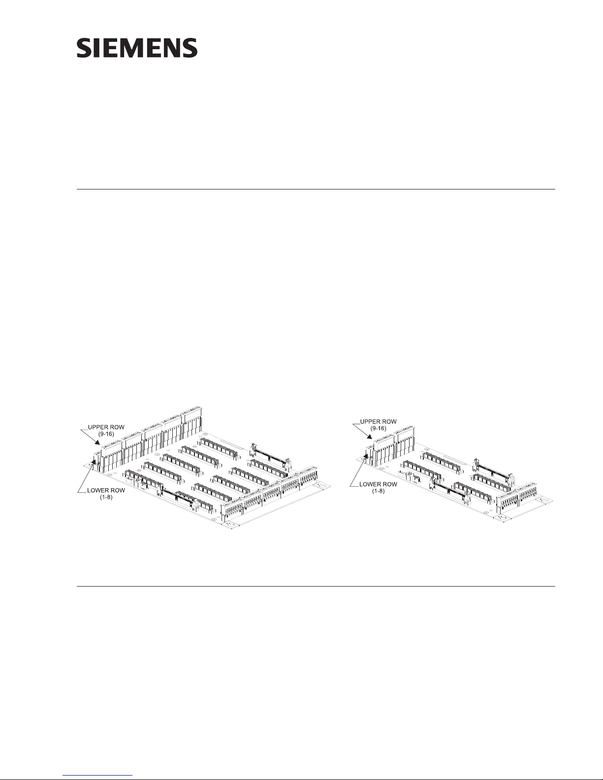
Each row of studs in the backbox or each Mounting Plate can hold a maximum of
two CC-5 cardcages. There are three possible locations for mounting the CC-5.
1. Flush left in the backbox or on the Mounting Plate in positions 1-2.
2. In the center of the row in the backbox or on Mounting Plate in positions 2-3.
3. Flush right in the backbox or on the Mounting Plate in positions 3-4.
The CC-2 is most effectively used to add two more card slots in a row that already
has one CC-5 and another 1-position module (i.e., PSC-12). It is best installed in a
position adjacent to the CC-5.
When only one CC-5 cardcage is to be installed, it is normally installed on the left
side of a row in the backbox or on the Mounting Plate.
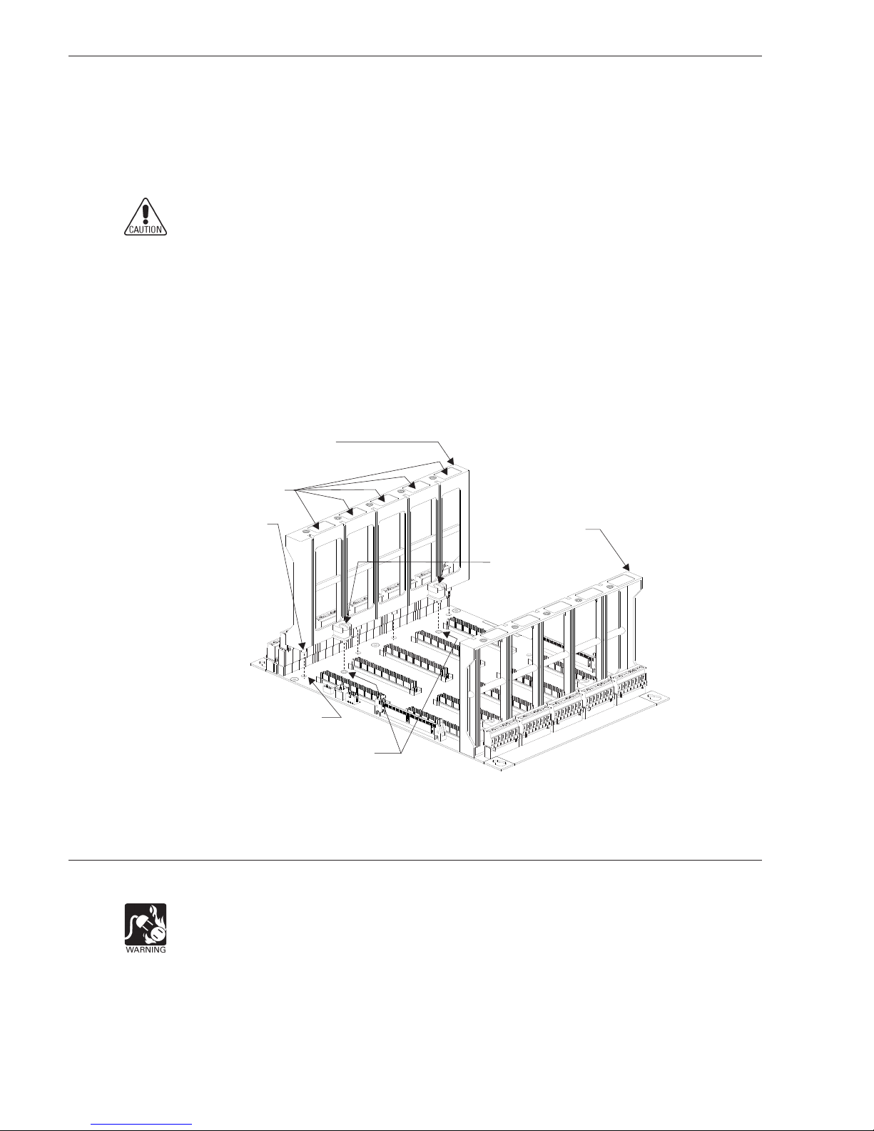
There is a top and bottom to the Mounting Plate.The top is where the word “TOP” is
stamped on the Mounting Plate.When the cardcage is mounted correctly on the
Mounting Plate it will be flush on the top, bottom, and left with the Mounting Plate
and the two screw holes in the center of the cardcage motherboard will be over
threaded posts.
1. Install four 10-32 screws in the threaded posts at the top left of Position 1,
top right of Position 2, bottom left of Position 1, and the bottom right of
Position 2 on the Mounting Plate. Screw each of the 10-32 screws into the
threaded posts 5-6 turns. (Refer to Figure 3.)
2. Place the cardcage over the four screws on the Mounting Plate and slide it
down or towards you to rest on the four screws. (Refer to Figure 4.) When
the cardcage is in the correct position it will be flush with the top, bottom,
and left side of the Mounting Plate.
3. Install the two 10-32 screws in the center of the cardcage motherboard
near the left and right edge.
4. Tighten the six screws.

Siemens Industry, Inc.
Building Technologies Division
P/N 315-033035-64
TOP
CC-5 TOP THREADED POSTS CC-2 TOP THREADED POSTS
CC-5 BOTTOM THREADED POSTS CC-2 BOTTOM THREADED POSTS
POSITION 1 POSITION 3 POSITION 4
POSITION 2
POSITION 1 POSITION 3 POSITION 4
POSITION 2
CAB-MP
Figure 4
Location Of The CC-5 and CC-2 On The Optional CAB-MP
TOP
SLIDE DOWN CARDCAGE UNTIL
FLUSH ON TOP, LEFT, AND BOTTOM
CAB-MP
CC-5
CARDCAGE
CC-2
CARDCAGE
INSTALL TWO 10-32 SCREWS WHEN
ALIGNED WITH THREADED STUDS
Figure 5
Mounting The CC-5 and CC-2 On The Optional CAB-MP

Siemens Industry, Inc.
Building Technologies Division
P/N 315-033035-65
WIRING At the top and bottom of the CC-5 and CC-2 and adjacent to each card slot are
removable terminal blocks. The wiring to the two terminal block connectors at the top
of the CC-5 and CC-2 is power limited. The wiring to the terminal block connector at
the bottom of the CC-5 and CC-2 is non-power limited.
To Connect External Wiring
To The Card Slots: (Figure 6)
1. Insert the wire to be connected in the desired opening in the side of the
removable terminal block.
2. Tighten the appropriate locking screw.
Figure 6
Removable Terminal Block On The CC-5 and CC-2
To Connect The
Data Bus: The Data bus connectors on the cardcage motherboard are P1 and P2. (Refer to
Figure 7.) They are 60 pin, keyed, male connectors with connector extractors.
1. Open the connector ejectors out of the vertical position and away from the
connector body.
2. Insert the female cable connector into the male connector (P1 or P2) on the
cardcage motherboard. Gently press the cable connector into the
motherboard connector. As the cable connector is pressed in, the connector
ejectors will begin to move to the vertical position. When the cable connec-
tor is fully seated the connector ejectors will be vertical.
Use the 60 pin bus cable - long, P/N 500-633997 when the PSC-12/PSX-12 is located
in a different row in the backbox or on a different CAB-MP.

Siemens Industry, Inc.
Building Technologies Division
P/N 315-033035-66
To Connect The CAN Bus: The CAN bus (P3) is a six pin connector located just above P1 on the cardcage
motherboard. (Refer to Figure 7.) It is used to supply CAN communications and
power to the LED Control Modules (LCM), Switch Control Modules (SCM), Control
Modules (FCM), Master Voice Microphone (LVM) and Master Firefighters Telephone
(FMT).The connector is keyed and requires no special instructions for cable connec-
tion. Use cable CCL, P/N 500-634214 to connect from CAN bus (P3) on CC-5 and CC-
2 to the desired module. CAN power must be supplied to E11 (CC-5) or E5 (CC-2)
Refer to Figure 8 for wiring details.
CONNECTOR EJECTORS
IN VERTICAL POSITION
Figure 7
Location Of Connectors (CC-5 Shown)
Figure 8
Connecting Power For CAN Bus

Siemens Industry, Inc.
Building Technologies Division
P/N 315-033035-67
SPECIFICATIONS Physical Specifications: CC-5 10.58”W x 14.25”H
CC-2 4.78”W x 14.25”H
Electrical Ratings: The PSC-12 supplies the power to the two 60-pin Data
bus connectors (P1 and P2) in the CC-5 and CC-2.The
total rating on P1 and P2 for all CC-5s in any given
enclosure is as follows:
24 VDC, 2 Amps max
6.2 VDC, 2 Amps max
See PSC-12 Installation Instructions, P/N 315-033060, and the PSX-12 Installation
Instructions, P/N 315-034050, for complete power supply loading calculations.

Siemens Industry, Inc.
Building Technologies Division
Florham Park, NJ
Siemens Canada, Ltd.
1577 North Service Road East
Oakville, Ontario
L6H 0H6 Canada
P/N 315-033035-6Siemens Gebäudesicherheit
GmbH & Co. oHG
D-80930 München
For CE applications in Cerberus E100 systems refer to
Installation Instruction A24205-A334-B844 (English) or A24205-A334-A844 (German).
Document ID A6V10239102
Cyber security disclaimer
Siemens products and solutions provide security functions to ensure the secure operation of
building comfort, fire safety, security management and physical security systems. The security
functions on these products and solutions are important components of a comprehensive security
concept.
It is, however, necessary to implement and maintain a comprehensive, state-of-the-art security
concept that is customized to individual security needs. Such a security concept may result in
additional site-specific preventive action to ensure that the building comfort, fire safety, security
management or physical security system for your site are operated in a secure manner. These
measures may include, but are not limited to, separating networks, physically protecting system
components, user awareness programs, defense in depth, etc.
For additional information on building technology security and our offerings, contact your Siemens
sales or project department. We strongly recommend customers to follow our security advisories,
which provide information on the latest security threats, patches and other mitigation measures.
http://www.siemens.com/cert/en/cert-security-advisories.htm
This manual suits for next models
1
Table of contents
Other Siemens Chassis manuals
Popular Chassis manuals by other brands

nvent
nvent CPCI user manual

Comet Models
Comet Models LCP33 instructions

National Instruments
National Instruments cDAQ-9188XT user manual

IEI Technology
IEI Technology BRICK Series Quick installation guide

IEI Technology
IEI Technology RACK-3200G Quick installation guide

Transition Networks
Transition Networks CPSMC0800-100 user guide