Siemens SIMATIC SBS1-50 User manual

© Siemens AG 2019. Alle Rechte vorbehalten
A5E43186448B_AD_004, 05/2019 1
SIMATIC
MICRO-DRIVE PDC Schirmbügel-Set
Kompaktmontageanleitung
Anwendungsbereich
Schirmbügel-Set für die EMV-gerechte Anbindung von
Signal-, Geber- und Leistungsleitungen an den SIMATIC
MICRO-DRIVE PDC.
Lieferumfang
Bezeich-
nung
Artikelnummer
Lieferumfang
SBS1-50 6BK1638-
0XA50-0AA0
•1 x Schirmbügel
•3 x Klemmbügel
•1 x Erdungsband mit 2 x
Befestigungsschrauben
•Kompaktmontageanleit-
ung
SBS1-70 6BK1638-
0XA70-0AA0
•1 x Schirmbügel
•4 x Klemmbügel
•1 x Erdungsband mit 2 x
Befestigungsschrauben
•Kompaktmontageanleit-
ung
SBS1-110 6BK1638-
0XA10-0AA0
Sicherheitshinweise
WARNUNG
•Das zu dieser Dokumentation zugehörige
Produkt/System darf nur von für die jeweilige
Aufgabenstellung qualifiziertem Personal gehandhabt
werden. Qualifiziertes Personal ist auf Grund seiner
Ausbildung und Erfahrung befähigt, im Umgang mit
diesen Produkten/Systemen Risiken zu erkennen und
mögliche Gefährdungen zu vermeiden.
WARNUNG
Gefahr durch Stromschlag
Lebensgefahr oder schwere Verletzungsgefahr
•Im Schaltschrank kommen Spannungen > 60 V vor.
Deshalb sind bei Inbetriebnahme- und
Wartungsarbeiten geeignete Sicherheitsvorkehrungen
gegen Berühren zu treffen.
•Stellen Sie vor dem Arbeiten im Schaltschrank sicher,
dass die Anlage spannungsfrei ist.
Schirmbügel montieren
Schrauben Sie die Schirmbügel oberhalb und unterhalb der
Profilschiene an der Montageplatte fest.
Hinweis
Sie benötigen zwei Schirmbügel
-Sets.
Der zulässige Abstand zwischen SIMATIC MICRO-DRIVE
PDC und Schirmbügel beträgt minimal 30 mm und maximal
50 mm.
①
Schirmbügel oben für Klemmbügel Hardware-STO,
SSI-Geber, digitale Ein- und Ausgänge (z. B.
Motorbremse), fehlersichere Ausgänge
②
Schirmbügel unten für Klemmbügel Motorleitung,
Encoder- und Hall-Geberleitung, fehlersichere
Eingänge

MICRO-DRIVE PDC Schirmbügel-Set
2A5E43186448B_AD_004, 05/2019
Kabelschirm auflegen
Folgende Prozesssignale des SIMATIC MICRO-DRIVE
PDC müssen Sie über geschirmte Leitungen anschließen:
●Encodersignale
●Hall-Gebersignale
●Prozesssignale mit Leitungen ≥ 2 m
Legen Sie dazu die Schirme der Leitungen mit Hilfe der
Klemmbügel auf den oberen und unteren Schirmbügel auf.
Gehen Sie wie folgt vor:
1. Isolieren Sie das Kabel ab.
1) Länge ist abhängig vom Abstand zwischen
Schirmbügel und Gerät
2. Drücken Sie die Klemmbügel auf das Schirmgeflecht
des Kabels.
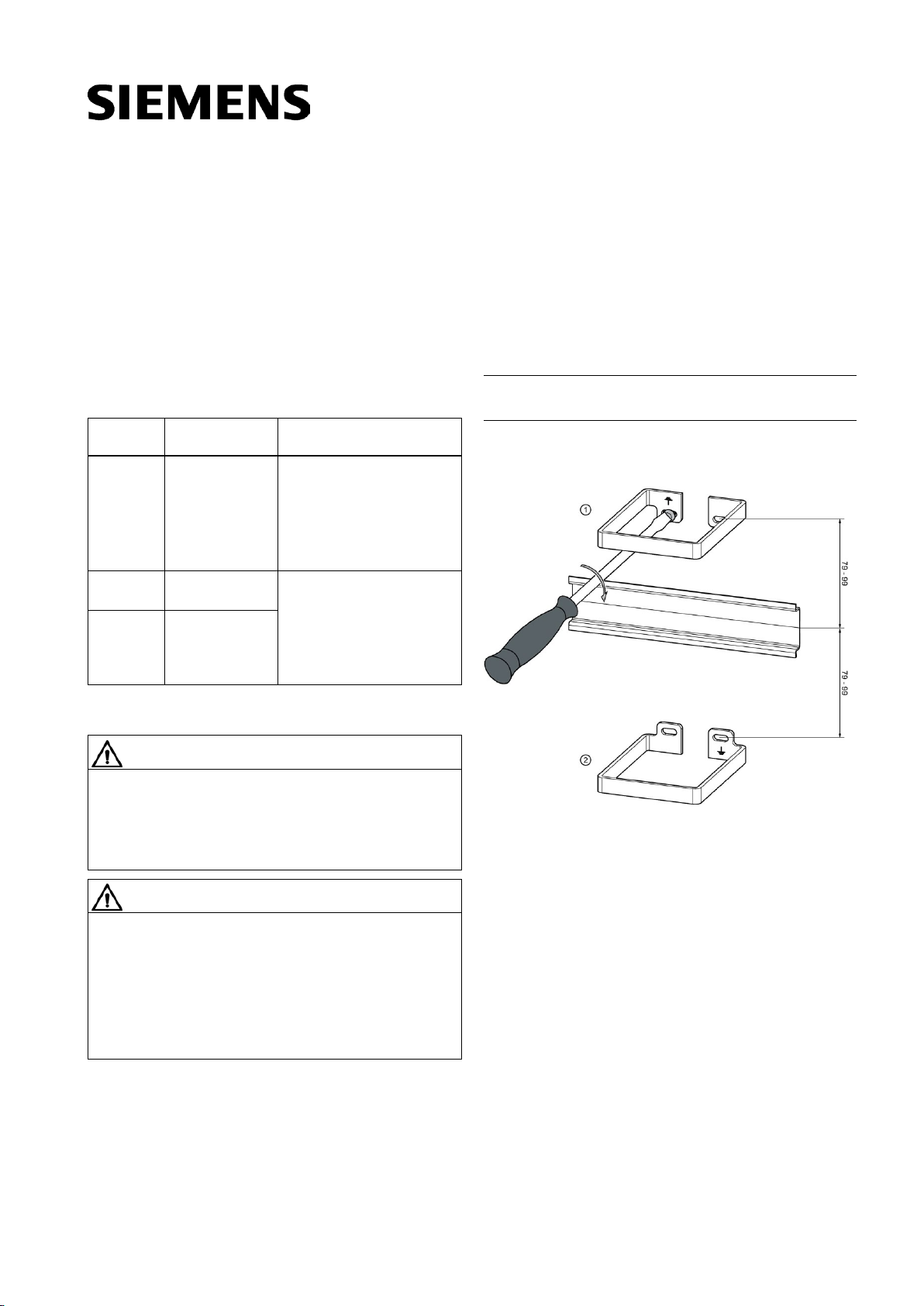
3. Schieben Sie die Klemmbügel mit Kabel auf den
Schirmbügel.
Klemmbügel mit Kabel auf den Schirmbügel schieben
(schematische Darstellung)
Funktionserde anschließen
●Die Montageplatte darf im Auflagebereich der
Schirmbügel nicht lackiert sein und muss an der
Schrankerde niederimpedant angeschlossen sein.
●Der Leiterquerschnitt muss 2 mm2(AWG14) betragen.
●Achten Sie darauf, dass die Leitung der Funktionserde
so kurz wie möglich ist.
●Die Ausführung der Funktionserde (FE) darf nicht mit
einem gelb-grünen Leiter realisiert werden.
Gehen Sie wie folgt vor:
Verbinden Sie alle Klemmen mit dem Symbol mit den
Verschraubungen der Schirmbügel.
Verwenden Sie für den Anschluss der Funktionserde des
PDC das Erdungsband (als Zubehör/ Ersatzteil bestellbar).
1. Schrauben Sie das Erdungsband an dem dafür
vorgesehenen Erdungsanschluss auf der Unterseite des
Gehäuses an.
2. Befestigen Sie das andere Ende des Erdungsbandes an
Masse, z. B. am Schirmbügel oder am Chassis.
Weitere Dokumentation
Weiterführende Informationen finden Sie im
Systemhandbuch SIMATIC MICRO-DRIVE PDC (siehe
Siemens Industry Online Support
(https://support.industry.siemens.com)).
MICRO-DRIVE PDC Schirmbügel-Set
A5E43186448B_AD_004
, 05/2019
Siemens AG
Division Digital Factory
Postfach 48 48
90026 NÜRNBERG
DEUTSCHLAND

© Siemens AG 2019. All rights reserved
A5E43186448B_AD_004, 05/2019 3
SIMATIC
MICRO-DRIVE PDC shield bracket set
Compact Hardware Installation Instructions
Application
Shield bracket set for the EMC-compliant connection of
signal, encoder and power cables to the SIMATIC MICRO-
DRIVE PDC.
Scope of supply
Design-
ation
Article number
Scope of supply
SBS1-50 6BK1638-
0XA50-0AA0
•1 x shield bracket
•3 x terminal clamps
•1 x grounding strap with
2 x fixing screws
•Compact installation
instructions
SBS1-70 6BK1638-
0XA70-0AA0
•1 x shield bracket
•4 x terminal clamps
•1 x grounding strap with
2 x fixing screws
•Compact installation
instructions
SBS1-110 6BK1638-
0XA10-0AA0
Safety guidelines
WARNING
•The product/system described in this documentation
may only be operated by personnel qualified for the
specific task in hand. Qualified personnel are those
who, based on their training and experience, are
capable of identifying risks and avoiding potential
hazards when working with these products/systems.
WARNING
Electric shock hazard
Can cause death or serious injury
•Voltages of more than 60 V can occur in the control
cabinet. Suitable safety precautions preventing contact
must therefore be taken before and during
commissioning and maintenance work.
•Before working in the control cabinet, ensure that the
system is disconnected.
Mounting the shield bracket
Screw the shield brackets to the mounting plate above and
below the mounting rail.
Note
You need two shield bracket sets.
The permissible distance between SIMATIC MICRO-DRIVE
PDC and the shield bracket is a minimum of 30 mm and a
maximum of 50 mm.
①
Shield bracket above for clamp terminal hardware
STO, SSI encoder, digital inputs and outputs (e.g.
motor brake), fail-safe outputs
②
Shield bracket below for clamp terminal motor cable,
encoder and Hall encoder cable, fail-safe inputs

MICRO-DRIVE PDC shield bracket set
4A5E43186448B_AD_004, 05/2019
Attaching the cable shield
You have to connect the following process signals of the
SIMATIC MICRO-DRIVE PDC using shielded cables:
●Encoder signals
●Hall encoder signals
●Process signals with cables ≥ 2 m
To do this, place the shields of the cables on the upper and
lower shield bracket with the help of the clamp terminal.
Proceed as follows:
1. Strip the cable.
1) Length depends on the distance between shield
bracket and device
2. Press the terminal clamps onto the protective braided
shield of the cable.
3. Slide the terminal clamps with cables onto the shield
bracket.
Slide the terminal clamps with cables onto the shield
bracket (diagram)
Connecting to functional ground
●The mounting plate must not be painted in the contact
area of the shield bracket and must be connected to the
cabinet ground with low-impedance.
●The conductor cross-section must be 2 mm2(AWG14).
●Ensure that the cable for the functional grounding is as
short as possible.
●The functional grounding (FE) must not be made using a
green/yellow conductor.
Proceed as follows:
Connect all terminals with the symbol to the screw
connections of the shield brackets.
To connect the functional grounding of the PDC, use the
ground strap (available as accessory / spare part).
1. Screw the grounding strap to the ground connection
provided for this purpose on the bottom of the housing.
2. Fix the other end of the grounding strap to ground, e.g.
on the shield bracket or the chassis.
Additional documentation
You can find more information in the SIMATIC MICRO-
DRIVE PDC system manual (see Siemens Industry Online
Support (https://support.industry.siemens.com)).
MICRO-DRIVE PDC shield bracket set
A5E43186448B_AD_004
, 05/2019
Siemens AG
Division Digital Factory
Postfach 48 48
90026 NÜRNBERG
GERMANY
This manual suits for next models
5
Table of contents
Languages:
Other Siemens TV Mount manuals