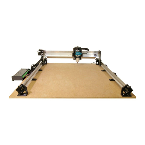
Sienci Labs LongMill MK2 User manual

LongMill MK2 48” Extension Kit

Table of Contents
2
48” X-axis rail box unpacking 3
Hardware box 3
Drag chain & cable box 4
Y-axis gantry plate box 4
Tools you’ll need 4
Missing/broken parts? 5
Assembly tips 5
Drag chain and wiring disassembly 7
Disassembling the drag chains 7
Disconnecting wiring 9
Parts to be reused 10
X-axis disassembly 11
Dismounting machine 11
X-axis motor and leadscrew removal 12
X-axis rail disassembly 16
Y-axis gantry disassembly 19
Parts to be reused 21
48” Extension X-axis assembly 22
EX Y-gantry plate assembly 22
EX X-axis preparation 26
EX X-axis rail mounting 29
X-axis motor mounting 31
X-axis lead screw installation 32
Drag chain and wiring installation 38
Attaching drag chains 38
Organizing excess cable lengths 43
Reconnecting control box 48
Tuning movement 48
Table mounting 48

Congratulations on getting your LongMill MK2 48” extension kit! In just a few steps, you’ll soon have a much
larger CNC with 56% more cutting area than before, as well as the ability to pass full width 4’ sheets of material
through.
Please read this whole section before continuing on with assembly. It will provide you with the startup
information and context needed to have a smooth and successful assembly.
48” X-axis rail box unpacking
Inside the 48” X-axis rail box, you’ll find the X-axis rail packaged with 5 boxes.
The ‘EX hardware box’ contains various hardware that is used when assembling the extension kit, the EX drag
chain & cable box contains a longer 1400mm drag chain and various cables, the Y-axis gantry plates box contains
the two EX Y-gantry plates, and the MK2 EX hardware box contains some small parts specific to this extension kit.
The last box serves to fill empty space inside the rail box and better protect the X-axis rail during shipping. You’ll
want to unpack all hardware from these boxes and set this aside for whenever it is called during assembly.
EX Hardware box

EX Drag chain & cable box
MK2 EX hardware box

EX Y-axis gantry plate box
Tools you’ll need
You’ll need these tools on hand for assembly. Most people will have these in their shop:
●Metric Allen keys (we provide)
●Metric wrenches, metric socket set, or adjustable wrenches.
●A small flat head screwdriver
We don’t recommend you use an impact driver for assembly except when mounting the machine because you
won’t save much time and some assemblies are prone to damage if they’re overtightened
Missing/broken parts?
Don’t sweat it - your kit has spares and redundancy included. If a part is lost or isn’t going together how you
expect, no worries; just check through the bags and you’ll likely find what you need to continue assembly. Expect
some bolts left over at the end and feel free to set these aside for future machine maintenance.
We supply extra parts so that:
●If a part doesn’t work properly the extra one can be used instead
●If you lose something (especially small things) you don’t have to search the floor
●We reduce the chance of packing too few on our end
If a part is missing completely, check that you’re looking for the right thing and ensure you look through all the
packaging you received with your extension kit. Some parts and add-ons such as the t-tracks ship in a separate
package if they can’t fit into the same box.
If a part arrives broken and doesn’t have a spare, the LongMill extension kit’s warranty covers replacement parts
and we’ll even be happy to help you out if you break it yourself. Just shoot us a message here

(https://sienci.com/contact-us/) and see if there are any other areas of assembly you can continue with in the
meantime. We’ll get back to you as soon as we can.
Assembly tips
1. Take breaks when needed
The disassembly and reassembly process can take a few hours. Pace yourself and enjoy the process.
2. Read the instructions
Many issues during assembly can be solved by re-examining the instructions. Check that you didn’t skip a
page and that you completed the previous step correctly. Some steps are hard to explain and some parts
have names that are hard to remember so looking at the pictures more closely can also help you to better
understand what needs to be done. Reading is encouraged if you’d like more detail on where to locate the
part, what function it serves on the machine, and other elaborative information.
Our assembly videos can’t be updated as often as the online or PDF instructions so if packaging or parts
change the written manual will always be able to clarify these changes.
3. Remember the language
This manual contains some technical language as well as a distinct visual language. Keeping these in mind
will make the assembly easier for you to understand and ensure that less mistakes happen.
Section title pages: show the part of the machine you’ll be working on next
Rotation arrows: come as either blue or red, blue indicating a loose placement of the part and red
indicating a firm tightening required to fasten the part into place
Caution triangles: marks something that requires attention
Large green circles: provide a secondary view of the current step for added clarity
X, Y, and Z: during assembly if you see these capitalized letters used it’s because we refer to some parts by
the axis they belong to. For reference, if you’re looking at the Longmill from the front the X-axis is when
the machine moves left/right, the Y-axis is towards/away from you, and the Z-axis is moving up/down from
the tabletop
4. Set aside a clean space for disassembled parts
Since installing this extension kit will require the removal of some parts, as well as the reusing of some,
make sure you can set these parts aside without losing any or mixing anything up.
This manual will specify which parts will and will not be reused for final assembly of the 48x30” machine.

Drag chain and wiring disassembly
Disassembling the drag chains
On the Y-axis drag chain, start unclipping any of the clips securing the wires along the Y-axis. Detach the start and
end links from this drag chain, then remove the drag chain entirely.

Disconnect the X-axis motor connector.
On the X-axis drag chain, unclip the clips securing the wires along the X-axis. Detach the start and end links from
this drag chain, then remove the drag chain entirely.

Disconnecting wiring
Disconnect the motor cables going to the Z-axis motor and X-axis motor. Disconnect and remove any other
add-ons such as limit switches or laser if installed. Disconnect any of these cables from your control box as well.

Remove the router from the router mount by loosening the two M5 screws at the front of the router mount. Slide
the router body out and remove any zip ties holding the router power cord if applicable. Set the router aside for
re-installation later on.

Parts to be reused
Set aside any cables removed, router, as well as the shorter Y-axis drag chain.
Discard the longer X-axis drag chain - this won't be reused during reassembly.

X-axis disassembly
Dismounting machine
Before beginning the disassembly and replacement of components which make up the X-axis of the machine, start
by unmounting the machine from your current wasteboard. Undo each of the eight wood screws installed on the
left and right sides of your machine.

X-axis motor and leadscrew removal
Working backwards from how your LongMill was assembled, we’ll first start by removing the X-axis motor, then
X-axis lead screw. First, loosen the coupler clamping screw at the lead screw side as shown.
Unscrew each of the four M5-50mm screws holding the motor onto the Y-gantry plate. While doing so, be careful
not to lose any of the nylon washers or aluminum standoffs which may slide off the four screws. Set this motor
with these screws, standoffs, and nylon washers aside for now - these will be reused later.

On the removed X-axis motor assembly, loosen the coupler screw at the motor side, and remove this coupler from
the motor.
At the left side of the machine where the motor assembly was removed, slide the flange bearing out of the
Y-gantry plate and off of the lead screw.

At the opposite side, pull the brass ACME locking nut and lead screw to slide the XZ gantry and lead screw to the
right and out of the left Y-gantry plate.
Turn the lead screw counter-clockwise by hand to unthread it from behind the XZ gantry assembly. Once fully
unthreaded, remove the leadscrew from the machine by removing it from the right side. This lead screw can be
discarded as it will not be reused later on.


X-axis rail disassembly
Remove the four M5-25mm screws on the left Y-gantry plate as shown, leaving the X-axis rail to rest on the drag
chain mount.
Lift the X-axis rail slightly, then pull out the entire left Y-axis rail and gantry from underneath. Rest the X-axis rail
on the wasteboard for now.

Slide XZ gantry assembly to the left, removing it from the X-axis rail entirely.

At the right Y-gantry plate, undo the four M5-25mm screws to completely detach the X-axis rail.
Remove the drag chain mount and drag chain end link from the left side of the X-axis rail by loosening all three
M5-10mm bolts and sliding the components off. Set the X-axis rail and drag chain mount with screws aside. The
drag chain mount and drag chain end link will be getting reused later, but the X-axis rail will of course not be.

At this point, you’ll want to transfer the two Y-axis rail assemblies and XZ-gantry assembly onto your larger MDF
waste board since the soon-to-be 48x30” machine likely will not fit on your existing wasteboard anymore.
Y-axis gantry disassembly
Since the left and right Y-axis rails are perfectly mirrored assemblies, repeat any of the steps for this section on
both Y-axis rail assemblies. Start by removing the two M5-25mm screws which attach the Y-gantry plate to the
delrin nut behind it.
Other manuals for LongMill MK2
1
Table of contents
Other Sienci Labs Wood Router manuals
