SIFA 1250 User manual

USER'S MANUAL
Instructions for Use
Assembly
Maintenance
TECHNISCHE ANLEITUNG
Bedienungsanweisung
Montage
Wartung
GUIDE TECHNIQUE
Utilisation
Assemblage
Entretien
MODULO SELF SERVICE FREDDO STATICO
Cold Snack Unit - Theke für Kaltspeisen - Buet froid
GUIDA TECNICA
Istruzioni di uso-Montaggio-Manutenzione
ANNO DI COSTRUZIONE MATRICOLA
Year of Manufacture
Baujahr
Année de construction
Serial number
Seriennummer
Numéro de série
Società Industria Frigoriferi e Arredamenti S.p.a.
Via Nazionale, 15/19 Tel. 0039-(0)721-4741
61022 COLBORDOLO (PS) ITALY Fax 0039-(0)721-497507
Sito Internet: http://www.sifaspa.it
SS 07-04

MATRICOLA
Serial number -Seriennummer -Numéro de série
SELF SERVICE
Cold Snack Unit-Theke für Kaltspeisen-Buet froid
ANNO DI COSTRUZIONE
Year of Manufacture-Baujahr -Année de construction
Società Industria Frigoriferi e Arredamenti S.p.a.
Via Nazionale, 15/19
61022 COLBORDOLO (PS) ITALY
Tel. 0039-(0)721-4741
Fax 0039-(0)721-497507
Sito Internet: http://www.sifaspa.it
4
GB
I
SIMBOLOGIA
(1) Questo simbolo indica pericolo e verrà
utilizzato tutte le volte che sia coinvolta la
sicurezza dell’operatore
(2) Questo simbolo indica cautela e vuole ri-
chiamare l’attenzione su operazioni di vitale
importanza per un funzionamento corretto e
duraturo della macchina
(3) La presenza di questo simbolo sulla mac-
china indica cautela perché ci sono dei circuiti
sotto tensione elettrica
(4) La presenza di questo simbolo sulla mac-
china indica il punto di messa a terra della
macchina.
GENTILE CLIENTE
per la sicurezza dell’operatore, i dispositivi della vetrina
devono essere tenuti in costante ecienza.
Questo libretto ha lo scopo di illustrare l’ uso e la ma-
nutenzione della vetrina e l’operatore ha il dovere e la
responsabilità di seguirlo.
ATTENZIONE!
Quanto riportato in questo manuale riguarda
la vostra sicurezza.
Conservare con cura questo libretto per ogni
ulteriore consultazione.
L'installazione deve essere eettuata secondo
le istruzioni del costruttore e da personale
specializzato .
Per l'eventuale riparazione rivolgersi esclu-
sivamente ad un centro di assistenza tecnica
autorizzata dal costruttore, e richiedere l'utilizzo
di ricambi originali.
Il mancato rispetto di quanto sopra può com-
promettere la sicurezza dell'operatore.
SYMBOLS
(1) This symbol is used to indicate a potentially
hazardous situation and appears each time that
operator safety is at risk
(2) This symbol is used to indicate caution and
draws attention to those operations which are of
critical importance for the proper functioning
and long service life of the machine
(3) The presence of this symbol on the machine
is used to alert you to live circuits
(4) The presence of this symbol is used to indi-
cate the earthing point of the machine
DEAR CUSTOMER,
For operator safety, all display unit safety devices must be
kept in perfect working order.
This manual has been compiled to illustrate display unit
use and maintenance and it is the operator’s duty and re-
sponsibility to follow the instructions contained herein.
CAUTION!
The contents of this manual concern your
personal safety.
Keep this manual safely for further consulta-
tion.
The display unit must be installed by qualied
personnel and in accordance with the Manufac-
turer’s instructions.
Only use a Technical Assistance Service author-
ised by the Manufacturer and always ask for
original SIFA s.p.a. spare parts to be used.
Ignoring the above recommendations can com-
promise operator safety.
5
FD
SYMBOLIK
(1) Diese Symbol bedeutet Gefahr und wird immer
dann verwendet, wenn die Sicherheit des Bedieners
gefährdet ist.
(2) Diese Symbol bedeutet Vorsicht und lenkt die
Aufmerksamkeit auf Vorgänge, die für eine korrekte
und dauerhafte Funktionstüchtigkeit der Maschine
von grundlegender Wichtigkeit sind.
(3) Dieses Symbol bei der Maschine bedeutet Vorsicht,
da die Stromkreise unter Spannung stehen.
(4) Dieses Symbol bei der Maschine zeigt den Erdung-
spunkt der Maschine an.
SEHR GEEHRTER KUNDE,
zum Schutz des Bedieners müssen die Vitrinenvorrichtungen
laufend instandgehalten werden.
Dieses Handbuch soll die Bedienung und Wartung der Vitrine
erläutern, und der Bediener hat die Picht undVerantwortung,
die darin enthaltenen Anweisungen zu befolgen.
ACHTUNG!
Der Inhalt dieses Handbuches betrit Ihre Sicherheit.
Dieses Handbuch muß für eventuelle Informationen
sorgfältig aufbewahrt werden.
Die Installation muß, gemäß den Anweisungen des
Herstellers, von Fachpersonal durchgeführt werden.
Eventuelle Reparaturen sollen unter Verwendung
von Originalersatzteilen und ausschließlich von
technischen Kundendienstzentren, die vom Hersteller
autorisiert sind, durchgeführt werden.
Die Nichtbeachtung der zuvor genannten Punkte kann
die Sicherheit des Bedieners gefährden.
SYMBOLES
(1) Ce symbole indique un danger et il est utilisé
chaque fois que la sécurité de l’opérateur est
compromise
(2) Ce symbole invite à la précaution et il attire
l’attention en ce qui concerne des opérations
d’importance vitale pour le fonctionnement
correct et durable de la machine
(3) La présence de ce symbole sur la machine
invite à la précaution car il y a des circuits sous
tension électrique
(4) La présence de ce symbole sur la machine in-
dique le point de mise à la terre de la machine.
CHER CLIENT
pour la sécurité de l’opérateur, les dispositifs de la vitri-
ne doivent être maintenus constamment en conditions
d’ecacité.
Ce guide a pour but d’illustrer l’utilisation et l’entretien
de la vitrine et l’opérateur a le devoir et la responsabilité
de le respecter.
ATTENTION!
L’ensemble des indications reportées dans ce
guide concerne votre sécurité.
Conserver avec soin ce guide pour toute consul-
tation ultérieure.
L’installation doit être effectuée selon les in-
structions du constructeur et par le personnel
qualié.
Pour toute réparation éventuelle, s’adresser
exclusivement à un centre d’assistance techni-
que autorisé par le constructeur, et réclamer
l’emploi des pièces détachées originales.
Le non respect des instructions ci-dessus peut
compromettre la sécurité de l’opérateur.

6
GB
I
CONDIZIONI GENERALI DI
VENDITA E GARANZIA
1) La Ditta SIFA s.p.a. garantisce il proprio prodotto, in
condizioni di uso normale come da norme e dati tecnici
specicati nella documentazione illustrativa (non vi
sono garanzie per un uso diverso da quello descritto
nella documentazione SIFA s.p.a.) per un periodo di 12
mesi dalla consegna o ritiro della merce, a condizione
che l'apposito tagliando timbrato e dato dal Conces-
sonario, venga rispedito a SIFA s.p.a. entro dieci giorni
dalla consegna della stessa.
La garanzia termina 12 mesi dopo l'eettuazione della
fornitura, indipendentemente, dal fatto che i prodotti
siano stati o meno venduti.
2) Il Certificato di Garanzia dovrà essere conservato
dall'utilizzatore ed esibito ogni qualvolta si richieda un
intervento in garanzia. Il suo smarrimento o alterazione
tale da procurarne l'illeggibilità comporta l'immediato
decadimento della stessa.
3) La garanzia comprende: la sostituzione gratuita del
motocompressore o, in generale, di quelle parti dello
stesso motocompressore che ad insindacabile giudizio
della SIFA s.p.a., risultino difettose esclusivamente per
vizi di fabbricazione o materiale.
Fatta eccezione per quanto espressamente previsto nel
Certicato di garanzia si esclude ogni ulteriore forma
di garanzia espressa o tacita. Inoltre sono esclusi da
garanzia i danni conseguenti a trascuratezza , cattivo
uso o improprio, insuciente o non ordinaria manu-
tenzione, manomissione da parte del compratore o di
terzi, imperizia ed installazione non corrispondente
alle norme tecniche fornite dalla SIFA s.p.a., o altre
cause non imputabili alla venditrice stessa.
Nessun ampliamento della garanzia è dovuto alla SIFA
s.p.a. salvo casi sopra descritti.
4) L'eventuale sostituzione della parte difettosa non
comporta l'estensione o il rinnovo delle condizioni
di garanzia. Le parti difettose e/o sostituite devono
essere obbligatoriamente restituite alla SIFA s.p.a. in
porto franco.
L'installazione e l'assistenza in garanzia sono compe-
tenza del Concessonario presso il quale il prodotto è
stato acquistato.
5) Per eventuale controversia è fatta espressa deroga a
favore esclusivamente del Foro di Pesaro, con tacita
accettazione nora da parte dell'acquirente.
GENERAL CONDITIONS OF SALE
AND GUARANTEE
1) The Company SIFA s.p.a. guarantees this product in
conditions of normal use, as required by the stand-
ards and technical specications contained in the
illustrated documents (the Guarantee does not cover
any use other than that described in the SIFA s.p.a.
documents), for a period of 12 months from the date
of delivery or collection of goods. This Guarantee is
subject to the sending of the attached counterfoil,
stamped and dated by the Authorised Dealer, to SIFA
s.p.a. within ten days of delivery.
This guarantee expires 12 months from the date of de-
livery, independently of whether or not the machine
has been sold on.
2) The Guarantee Certicate must be retained by the
User and shown each time that servicing is requested
under guarantee. The loss of this Certicate or any
modication thereof, such as may bring about its illeg-
ibility, will render the Guarantee null and void.
3)The Guarantee covers: the replacement, free of charge
and at the sole option of SIFA s.p.a., of the motor-
driven compressor or, in general, of those parts which
due to defects in material or workmanship are judged
to be defective.
Excepting that specied in this Guarantee Certicate,
no other form of guarantee, either express or implied,
is given with respect to this product. Furthermore,
damage due to neglect, incorrect or misuse of the
product, maintenance or service not in accordance
with this manual, modications carried out by the
purchaser or third parties, inexperience and installa-
tion not in accordance with the technical standards
supplied by SIFA s.p.a., is not covered by the Guaran-
tee, nor is any other cause which cannot be attributed
directly to the Vendor.
No extensions of Guarantee coverage will be granted
by SIFA s.p.a., excepting in those cases described
above.
4) Any replacement of defective parts does not imply
the extension or renewal of these Guarantee condi-
tions. All defective and/or replaced parts shall be
returned, carriage paid, to SIFA s.p.a. Installation and
assistance under guarantee are the sole responsibil-
ity of the Authorised Dealer from whom the product
was purchased.
5) Any dispute arising from the present General Condi-
tions of Sale and Guarantee shall fall within the sole
competence of the Court of Pesaro, Italy, with the
tacit acceptance of the Purchaser.

7
FD
ALLGEMEINE VERKAUFS- UND
GARANTIEBEDINGUNGEN
1) Die Firma SIFA s.p.a. garantiert das Produkt für einen
Zeitraum von 12 Monaten ab Lieferung oder Abholung der
Ware unter derBedingung, daßesvorschriftsmäßig, lautden
indererklärendenDokumentationangegebenenNormenund
technischen Angaben, verwendet wird (es besteht keinerlei
Garantieanspruch,wenndasProduktnichtentsprechendden
AngabenderDokumentationderFirmaSIFAs.p.a.verwendet
wird),undunterderBedingung, daßdiemitStempelundDa-
tumdesHändlersverseheneGarantiekarteinnerhalbvonzehn
Tagen nach Lieferung an SIFA s.p.a. rückgesandt wird.
Die Garantie endet 12 Monate nach der Lieferung unabhän-
gig davon, ob die Produkte verkauft wurden oder nicht.
2) Der Garantieschein ist vom Abnehmer aufzubewahren und
jeweils bei Inanspruchnahme der Garantie vorzuzeigen. Bei
Verlegen bzw. Unleserlichkeit aufgrund von Veränderungen
verfällt jeglicher Garantieanspruch.
3) Unter die Garantieleistungen fallen: kostenloser Austausch
des Kompressors oder im allgemeinen der Kompressorteile,
die nach dem unanfechtbaren Urteil der Firma SIFA s.p.a.
ausschließlich aufgrund von Fabrikations- oder Materials-
chäden defekt sind.
Es gelten ausschließlich die im Garantieschein aufgeführten
Bestimmungen, jegliches anderweitige mündliche bzw.
stillschweigende Übereinkommen wird abgelehnt. Nicht
unter die Garantieleistungen fallen Schäden, die durch
Nachlässigkeit, unsachgemäßen oder unpassenden Ge-
brauch, unzureichende oder außerordentliche Wartung,
falsche Handhabung durch den Käufer oder Dritte, Uner-
fahrenheit, Installation nicht gemäß den von der Firma SIFA
s.p.a. gelieferten Fachnormen, oder aus anderen Gründen,
die nicht dem Verkäufer zugeschrieben werden können,
entstanden sind.
SIFA s.p.a. ist ausschließlich in oben genannten Fällen zu
Garantieleistungen verpichtet.
4)BeiAustauschdesdefektenTeilesbestehtkeineVerlängerung
oder Erneuerung der Garantie. Alle schadhaften und/oder
ausgetauschten Teile sind verbindlich der Firma SIFA s.p.a.
spesenfrei zurückzuerstatten.
Installation undKundendienst inderGarantiezeitunterliegen
derZuständigkeitdesVertragshändlers,beidemdasProdukt
gekauft wurde.
5)Bei eventuellenStreitfragenistausschließlich dasGerichtvon
Pesaro zuständig und wird schon jetzt vom Käufer stillsch-
weigend angenommen.
CONDITIONS GENERALES DE
VENTE ET DE GARANTIE
1) L’Entreprise SIFA s.p.a. garantit le produit, aux con-
ditions d’utilisation normale selon les normes et
données techniques spéciées dans la documen-
tation explicative (il n’y a pas de garantie pour un
usage diérent de celui décrit dans la documentation
SIFA s.p.a.) sur une période de 12 mois à dater de la
livraison ou du retrait de la marchandise, à condition
que le coupon portant le cachet du Concessionnaire
et la date d’achat soit retourné à Sifa s.p.a. dans les
dix jours successifs à la date de livraison de cette
marchandise.
La garantie échoit 12 mois après la livraison de la mar-
chandise, indépendamment du fait que les produits
aient été ou non vendus.
2) Le Certicat de Garantie devra être conservé par l’uti-
lisateur et présenté chaque fois qu’une intervention
sous garantie sera nécessaire. La perte ou altération
de ce Certicat entraînant son illisibilité comporte la
déchéance immédiate de la Garantie.
3) La garantie comprend: le remplacement gratuit du
motocompresseur ou, en général, des composants
du motocompresseur qui résultent, selon le jugement
sans appel de SIFA s.p.a., défectueux exclusivement
pour vices de fabrication ou de matériel.
Exception faite de ce qui est expressément prévu
dans le Certicat de Garantie, toute autre forme de
garantie tacite ou exprimée est exclue. En outre, la
garantie ne couvre pas: les dommages dérivant d’une
négligence, d’un usage impropre ou abusif, d’un en-
tretien insusant ou non périodique, d’une altération
de la part de l’acheteur ou de tiers, de l’inexpérience,
d’une installation non correspondante aux normes
techniques fournies par SIFA s.p.a., ou toute autre
cause non imputable au vendeur lui-même.
Aucune étendue de la garantie n’est due par SIFA
s.p.a.
4) Le remplacement éventuel de la partie défectueuse
ne comporte ni l’extension ni le renouvellement des
conditions de garantie. Les parties défectueuses et/ou
remplacées doivent être obligatoirement retournées
à SIFA s.p.a. franco de port.
L’installation et le service après-vente sous garantie
sont de compétence du Concessionnaire auprès
duquel le produit a été acheté.
5) Dans le cas d’une éventuelle controverse, une
dérogation expresse est faîte en faveur exclusive du
Tribunal de Pesaro, par acceptation tacite de la part
de l’acheteur.

8
GB
I
Sommario
1 SPECIFICHE TECNICHE.................................................................10
1.1 DESCRIZIONE DELLA VETRINA .........................................10
1.2 NORME APPLICATE................................................................12
1.3 POSTAZIONE DI LAVORO.....................................................14
1.4 ACCESSORI................................................................................14
1.5 IDENTIFICAZIONE ....................................................................14
1.6 DIMENSIONI DI INGOMBRO E PESI....................................16
1.7 CARATTERISTICHE TECNICHE ..............................................16
2 INSTALLAZIONE..............................................................................18
2.1 TRASPORTO .............................................................................18
2.2 SOLLEVAMENTO E MOVIMENTAZIONE ..........................18
2.3 SPECIFICHE AMBIENTALI .....................................................20
2.4 POSIZIONAMENTO................................................................20
2.4.1 CANALIZZAZIONE....................................................24
2.4.2 CANALIZZAZIONE TRA DUE VETRINE................24
2.5 COLLEGAMENTO ELETTRICO............................................26
2.6 COLLEGAMENTO IDRAULICO ...........................................26
2.7 NOTE AMBIENTALI .................................................................28
3 ESERCIZIO.........................................................................................30
3.1 OPERAZIONI PRELIMINARI DI CONTROLLO..................30
3.2 AVVIAMENTO E REGOLAZIONE DELLA
TEMPERATURA........................................................................30
3.3 FERMATA DELLA MACCHINA .............................................32
4 MANUTENZIONE ORDINARIA....................................................34
4.1 OPERAZIONI PRELIMINARI DI SICUREZZA ....................34
4.2 PULIZIA CONDENSATORE ...................................................34
4.3 PULIZIA VETRINA...................................................................36
- PULIZIA ESTERNO VETRINA .......................................................36
- PULIZIA INTERNO VASCA ...........................................................36
5 MANUTENZIONE STRAORDINARIA..........................................38
5.1 OPERAZIONI PRELIMINARI DI SICUREZZA ....................38
5.2 SOSTITUZIONE LAMPADE - REATTORI - STARTER ......40
6 ANOMALIE DI FUNZIONAMENTO...............................................42
7 CATALOGO RICAMBI........................................................................50
Contents
1 TECHNICAL SPECIFICATIONS.....................................................10
1.1 DESCRIPTION OF THE DISPLAY UNIT...............................10
1.2 STANDARDS AND REGULATIONS.....................................12
1.3 OPERATOR AREA ....................................................................14
1.4 ACCESSORIES...........................................................................14
1.5 PRODUCT IDENTIFICATION ................................................14
1.6 WEIGHTS AND OVERALL DIMENSIONS..........................16
1.7 TECHNICAL DETAILS .............................................................16
2 INSTALLATION.................................................................................18
2.1 TRANSPORT .............................................................................18
2.2 LIFTING AND HANDLING.....................................................18
2.3 AMBIENT CONDITIONS ........................................................20
2.4 POSITIONING...........................................................................20
2.4.1 CONNECTING UNITS ...............................................24
2.4.2 CANALIZZAZIONE TRA DUE VETRINE................24
2.5 ELECTRICAL CONNECTIONS...............................................26
2.6 COLLEGAMENTO IDRAULICO ...........................................26
2.7 ENVIRONMENTAL MEASURES............................................28
3 OPERATION ......................................................................................30
3.1 PRELIMINARY CHECKS .........................................................30
3.2 SWITCHING ON AND TEMPERATURE ADJUST-
MENT..........................................................................................30
3.3 SWITCHING OFF THE MACHINE ........................................32
4 ROUTINE MAINTENANCE............................................................34
4.1 PRELIMINARY SAFETY CHECKS .........................................34
4.2 CLEANING THE CONDENSER..............................................34
4.3 CLEANING THE DISPLAY UNIT ...........................................36
- CLEANING THE DISPLAY UNIT EXTERIOR..............................36
- CLEANING THE TRAY INTERIOR.................................................36
5 SPECIAL MAINTENANCE..............................................................38
5.1 PRELIMINARY SAFETY CHECKS .........................................38
5.2 REPLACING THE LAMP - BALLAST - STATER .................40
6 TROUBLESHOOTING.....................................................................44
7 REPLACEMENT PARTS CATALOGUE.........................................50

9
FD
Inhaltsverzeichnis
1 TECHNISCHE ANGABEN...............................................................11
1.1 BESCHREIBUNG DER VITRINE.............................................11
1.2 GÜLTIGE NORMEN ................................................................13
1.3 ARBEITSPLATZ.........................................................................15
1.4 ZUBEHÖR ................................................................................15
1.5 IDENTIFIZIERUNG...................................................................15
1.6 AUSMASSE UND GEWICHTE...............................................17
1.7 TECHNISCHE MERKMALE ....................................................17
2 INSTALLATION ................................................................................19
2.1 TRANSPORT .............................................................................19
2.2 HEBEN UND VERSTELLEN....................................................19
2.3 UMWELTBEDINGUNGEN......................................................21
2.4 POSITIONIEREN.......................................................................21
2.4.1 ZUSAMMENBAU .....................................................25
2.4.2 CANALIZZAZIONE TRA DUE VETRINE................25
2.5 ELEKTRISCHER ANSCHLUSS ...............................................27
2.6 COLLEGAMENTO IDRAULICO ...........................................27
2.7 HINWEISE ZUM SCHUTZ DER UMWELT..........................29
3 BETRIEB..............................................................................................31
3.1 VORKONTROLLEN..................................................................31
3.2 ANLAUF UND TEMPERATURREGELUNG.........................31
3.3 STILLSETZEN DER MASCHINE............................................33
4 WARTUNG ........................................................................................35
4.1 EINLEITENDE SCHUTZMASSNAHMEN............................35
4.2 KONDENSATORREINIGUNG................................................35
4.3 REINIGUNG VITRINE...............................................................37
- AUSSENREINIGUNG VITRINE......................................................37
- REINIGUNG KÜHLWANNE...........................................................37
5 AUSSERORDENTLICHE WARTUNG...........................................38
5.1 EINLEITENDE SCHUTZMASSNAHMEN............................38
5.2 AUSTAUSCH LAMPEN- DROSSELSPULEN- STARTER .41
6 BETRIEBSSTÖRUNGEN..................................................................46
7 ERSATZTEILKATALOG...................................................................51
Sommaire
1 SPECIFICATIONS TECHNIQUES..................................................11
1.1 DESCRIPTION DE LA VITRINE .............................................11
1.2 NORMES APPLIQUEES..........................................................13
1.3 POSITION DE TRAVAIL ..........................................................15
1.4 ACCESSOIRES...........................................................................15
1.5 IDENTIFICATION .....................................................................15
1.6 DIMENSIONS D’ENCOMBREMENT ET POIDS................17
1.7 CARACTERISTIQUES TECHNIQUES...................................17
2 INSTALLATION.................................................................................19
2.1 TRANSPORT .............................................................................19
2.2 SOULEVEMENT ET DEPLACEMENT..................................19
2.3 SPECIFICATIONS AMBIANTES ............................................21
2.4 POSITIONNEMENT.................................................................21
2.4.1 CANALISATION..........................................................25
2.4.2 CANALIZZAZIONE TRA DUE VETRINE................25
2.5 BRANCHEMENT ELECTRIQUE ............................................27
2.6 COLLEGAMENTO IDRAULICO ...........................................27
2.7 REMARQUES SUR L’ENVIRONNEMENT ...........................29
3 FONCTIONNEMENT ......................................................................31
3.1 OPERATIONS PRELIMINAIRES DE CONTROLE ..............31
3.2 DEMARRAGE ET REGULATION DE LA TEMPERA-
TURE ...........................................................................................31
3.3 ARRET DE LA MACHINE........................................................33
4 ENTRETIEN ORDINAIRE................................................................35
4.1 OPERATIONS PRELIMINAIRES DE SECURITE .................35
4.2 NETTOYAGE DU CONDENSEUR.........................................35
4.3 NETTOYAGE DE LA VITRINE ................................................37
- NETTOYAGE EXTERNE DE LA VITRINE ....................................37
- NETTOYAGE DE L’INTERIEUR DU BAC.....................................37
5 ENTRETIEN EXTRAORDINAIRE...................................................38
5.1 OPERATIONS PRELIMINAIRES DE SECURITE .................38
5.2 REMPLACEMENT LAMPE - REACTEUR - STARTER .......41
6 ANOMALIES DE FONCTIONNEMENT ......................................48
7 CATALOGUE DES PIECES DETACHEES.....................................51
10
GB
I
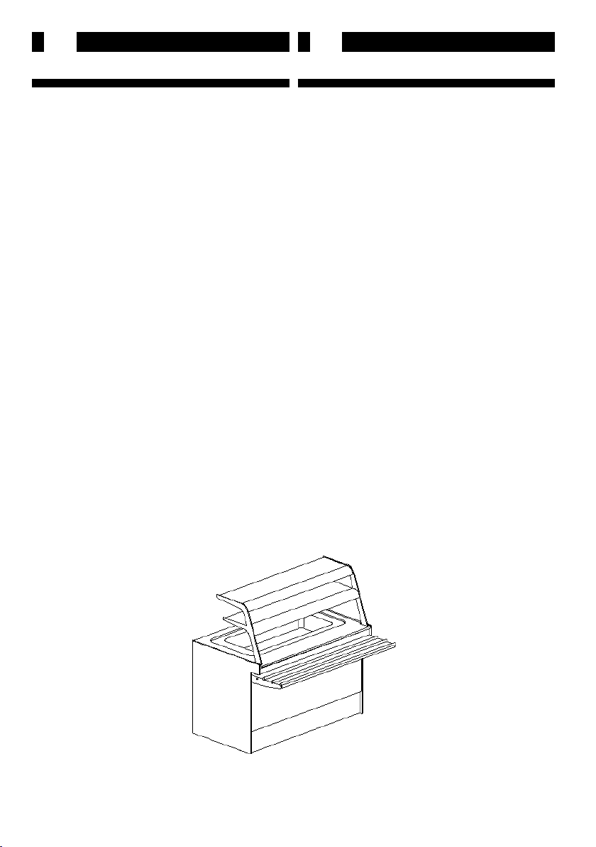
1 TECHNICAL SPECIFICATIONS
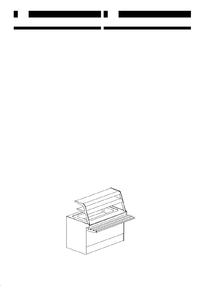
1.1 DESCRIPTION OF THE DISPLAY UNIT
The display unit comprises two basic sections:
1) Unit Supporting Structure
2) Refrigerating System
1) Unit Supporting Structure
- Cold Snack Unit
Connecting unit with metal frame body, varnished in
epoxy powders. Display surface insulated with CFC-free,
high-density polyurethane foam (40-45 kg/m3) and work
top in stainless steel AISI 304.
Struttura interna in alluminio anodizzato con pannelli
e schienale in melaminico smontabili, vano gruppo
posteriore in lamiera plasticata
Parte superiore costituita due centine portavetri in
acciaio inox di forte spessore lucidato a specchio e da
due vetri curvi temperati.
2) Refrigerating System
L’impianto di refrigerazione può essere solo incorpo-
rato.
Sul piano esposizione è ricavata una vasca gastronomia
di dimensioni 950x640 h=220, (capacità tre bacinelle
G/N 1/1).
La refrigerazione statica della vasca, avviene tramite
serpentina in rame, schiumata con poliuretano espanso,
a contatto con le pareti della vasca stessa.
La sua temperatura, viene regolata tramite termostato
manuale.
1 SPECIFICHE TECNICHE
1.1 DESCRIZIONE DELLA VETRINA
La vetrina è essenzialmente costituita da due sezioni:
1) Sezione struttura mobile portante
2) Sezione impianto di refrigerazione
1) Sezione struttura mobile portante
- Tavola fredda
Struttura in telaio metallico canalizzabile verniciato a
polveri epossidiche, vasca espositiva isolata con schiume
poliuretaniche ad alta densità (40/45 kg/m3) senza CFC,
e piano di lavoro in acciaio inox AISI 304.
Struttura interna in alluminio anodizzato con pannelli e
schienale in melaminico smontabili, vano gruppo poste-
riore in lamiera plasticata
Partesuperiore costituitaduecentineportavetriinacciaio
inox di forte spessore lucidato a specchio e da due vetri
curvi temperati.
2) Sezione impianto di refrigerazione
L’impianto di refrigerazione può essere solo incorpo-
rato.
Sul piano esposizione è ricavata una vasca gastronomia
di dimensioni 950x640 h=220, (capacità tre bacinelle
G/N 1/1).
La refrigerazione statica della vasca, avviene tramite
serpentinainrame, schiumataconpoliuretanoespanso,a
contatto con le pareti della vasca stessa.
La sua temperatura, viene regolata tramite termostato
manuale.
n°1
11
FD
1 TECHNISCHE ANGABEN
1.1 BESCHREIBUNG DER VITRINE
Die Vitrine besteht im wesentlichen aus zwei Teilen:
1) Tragstruktur
2) Kühlanlage
1) Tragstruktur
- Theke für Kaltspeisen
Struktur aus kombinierbarem Metallrahmen mit Epoxydpul-
verbeschichtung, die Ausstellungsäche ist mit hochdichtigen
PUR-Schäumen (40/45 kg/m3) ohne CFC isoliert, Arbeitsplatte
aus Inox-Stahl AISI 304.
Struttura interna in alluminio anodizzato con pannelli
e schienale in melaminico smontabili, vano gruppo
posteriore in lamiera plasticata
Parte superiore costituita due centine portavetri in
acciaio inox di forte spessore lucidato a specchio e da
due vetri curvi temperati.
2) Kühlanlage
L’impianto di refrigerazione può essere solo incorpo-
rato.
Sul piano esposizione è ricavata una vasca gastronomia
di dimensioni 950x640 h=220, (capacità tre bacinelle
G/N 1/1).
La refrigerazione statica della vasca, avviene tramite
serpentina in rame, schiumata con poliuretano espanso,
a contatto con le pareti della vasca stessa.
La sua temperatura, viene regolata tramite termostato
manuale.
1 SPECIFICATIONS TECHNIQUES
1.1 DESCRIPTION DE LA VITRINE
La vitrine est composée essentiellement de deux
sections:
1) Section structure de support
2) Section installation de réfrigération
1) Section structure de support
- Buet froid
Structure à châssis métallique canalisable peint en
poudres époxy, surface d’exposition isolée par mousses
polyuréthaniques à haute densité (40/45 kg/m3) sans
CFC, et plan de travail en acier inox AISI 304.
Struttura interna in alluminio anodizzato con pannelli
e schienale in melaminico smontabili, vano gruppo
posteriore in lamiera plasticata
Parte superiore costituita due centine portavetri in
acciaio inox di forte spessore lucidato a specchio e da
due vetri curvi temperati.
2) Section installation de réfrigération
L’impianto di refrigerazione può essere solo incorpo-
rato.
Sul piano esposizione è ricavata una vasca gastronomia
di dimensioni 950x640 h=220, (capacità tre bacinelle
G/N 1/1).
La refrigerazione statica della vasca, avviene tramite
serpentina in rame, schiumata con poliuretano espanso,
a contatto con le pareti della vasca stessa.
La sua temperatura, viene regolata tramite termostato
manuale.

12
GB
I
1.2 NORME APPLICATE
Lavetrina éconforme alladirettivasullacompatibilitàele-
tromagnetica 89/336-93/68 CEE e risponde alle norme:
EN 61000-3-2
Parte 3:Limiti
Sezione 2:Limite per le emissioni di corrente armonica
(apparecchiature con corrente di ingresso 16 A per fase).
EN 61000-3-3
Parte 3:Limiti
Sezione 3:Limiti delle uttuazioni di tensione del icker
insistemidialimentazioneinbassatensioneperapparec-
chiature con corrente nominale 16 A.
EN 55014-1
Limiti e metodi di misura delle caratteristiche di radio-
disturbo degli apparecchi elettrodomestici e similari o
termici, degli utensili elettrici e degli apparecchi elettrici
similari.
EN 55014-2
Requisiti di immunità per gli elettrodomestici, utensili e
degli apparecchi elettrici similari
Inoltre la vetrina è conforme alla direttiva sulla sicurezza
elettrica 73/23-93/68 CEE e risponde alle norme:
EN 60335-1
Parte 1: Norme generali
Sicurezza degli apparecch elettrici ad uso domestico e
similare.
EN 60335-2-24
Parte II: Norme particolari per frigoriferi e congelatori.
Uso degli apparecchi d’uso domestico e similare.
1.2 STANDARDS AND REGULATIONS
The refrigerated display unit complies with the electro-
magnetic compatibility standards 89/336-93/68 ECC and
with the following standards:
EN 61000-3-2
Part 3: Limits
Section 2: Limits for harmonic current emissions (equip-
ment input current 16 A per phase)
EN 61000-3-3
Part 3: Limits
Section 3: Limitation of voltage uctuations and icker
in low-voltage supply systems for equipment with rated
current 16 A.
EN 55014-1
Limitsandmethodsofmeasurementofradiodisturbance
characteristics of electrical motor-operated and thermal
appliances for household and similar purposes, electric
tools and similar electric apparatus.
EN 55014-2
Immunity requirements for household appliances, tools
and similar apparatuses
The glass case is also in compliance with the directive
on electrical safety 73/23-93/68 CEE and Product family
standard
EN 60335-1
Safety of household and similar electrical appliances.
EN 60335-2-24
Part II: Particular norms for refrigerators and freezers.
Use of household appliances and similar.

13
FD
1.2 GÜLTIGE NORMEN
Die Vitrine entspricht den Richtlinien überdie Elektro-
magnetische Kompatibilität 89/336-93/68 CEE und ist
normenmässig:
EN 61000-3-2
Teil 3: Grenzwerte
Hauptabschnitt2:GrenzwertefürOberschwingungsströme
(Geräte-Eingangsstrom 16 A je Leiter)
EN 61000-3-3
Teil 3: Grenzwerte
Hauptabschnitt3:GrenzwertefürSpannungsschwankun-
genundFlickerin Niederspannungsnetzenfür Geräte mit
einem Eingangsstrom 16 A.
EN 55014-1
Grenzwerte und Messverfahren für Funkstörungen
von Geräten mit elektromotorischem Antrieb und Ele-
ktrowärmegeräten für den Hausgebrauch und ähnliche
Zwecke, Elektrowerkzeugen und ähnlichen Elektrog-
eräten
EN 55014-2
Störfestigkeitsanforderungen für Haushaltsgeräte,
Werkzeuge und ähnliche Geräte
Produktfamilien-Norm
EN 60335-1
Sicherheit elektrischer Geräte für den Hausgebrauch und
ähnliche Zwecke Teil 1: Allgemeine Anforderungen.
EN 60335-2-24
Sicherheit elektrischer Geräte für den Hausgebrauch und
ähnliche Zwecke
Teil 2: besondere Anforderungen für Kühlschränke und
Gefriergeräte.
1.2 NORMES APPLIQUEES
La vitrine est conforme à la directive sur la compatibilité
électromagnétique 89/336-93/68 CEE et répond aux
normes:
EN 61000-3-2
Partie 3: Limites
Section 2: Limites pour les émissions de courant
harmonique (courant appelé pour les appareils 16 A
par phase).
EN 61000-3-3
Partie 3: Limites
Section 3: Limites des uctuations de tension et du ic-
ker dans les réseaux basse tension pour les équipements
ayant un courant appelé 16 A.
EN 55014-1
Limites et méthodes de mesure des perturbations
radioélectriques produites par les appareils électro-
domestiques ou analogues comportant des moteurs ou
des dispositifs thermiques, par les outils électriques et
par les appareils électriques analogues
EN 55014-2
Exigences d’immunité pour les appareils électrodome-
stiques, outils électriques et appareils analogues
Norme de famille de produits
EN 60335-1
Sécurité des appareils électrodomestiques et analo-
gues.
Première partie: Règles générales.
EN 60335-2-24
Sécurité des appareils électrodomestiques et analo-
gues
Deuxième partie: Règles particulières pour les réfrigéra-
teurs et congélateurs.
14
GB
I
1.3 OPERATOR AREA
The display unit operator area is situated behind the unit
itself and contains the on switch and temperature.
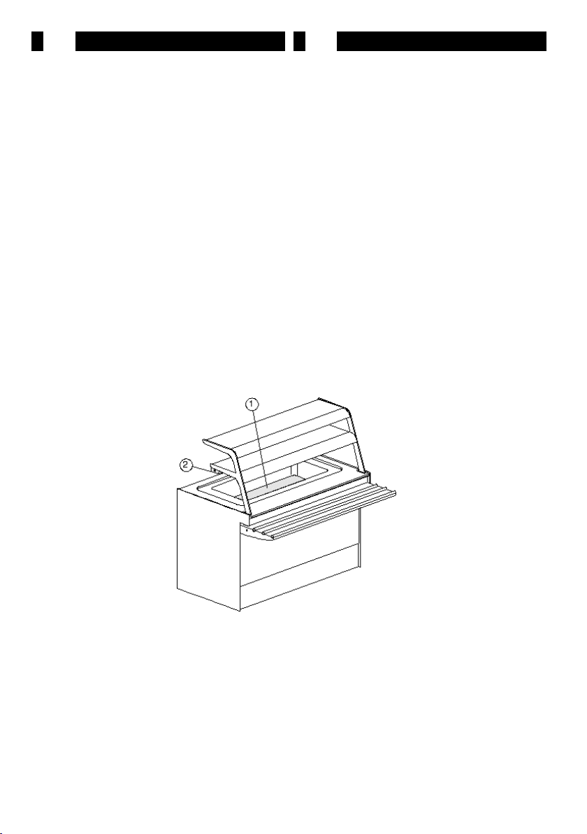
1.4 ACCESSORIES
Unit accessories are as follows (n°2):
- Rialzi interni alla vasca per una migliore esposizione
dei piatti o d'altro (pos.1);
- Illuminazione (pos.2).
1.5 PRODUCT IDENTIFICATION
In all communications to the Manufacturer or to repair
and services agents, please quote the display unit SERIAL
NUMBER which can be found xed to the plate on the
back (operator’s side) of the unit (n°3).
1.3 POSTAZIONE DI LAVORO
La zona di lavoro per la vetrina è posta nella parte poste-
riore di questa, dove vi sono i comandi di accensione e di
regolazione della temperatura.
1.4 ACCESSORI
Le parti accessorie della macchina sono (n°2):
- Rialzi interni alla vasca per una migliore esposizione
dei piatti o d'altro (pos.1);
- Illuminazione (pos.2).
1.5 IDENTIFICAZIONE
Perqualsiasicomunicazioneconilproduttoreoconicentri
assistenza citare sempre il NUMERO DI MATRICOLA
della vetrina, che è apposto sulla targhetta ssata sul lato
posteriore (lato operatore) della vetrina (n°3).
n°2

15
FD
1.3 ARBEITSPLATZ
Der Arbeitsplatz ist der rückwärtige Teil der Vitrine, wo sich
die Bedienungseinrichtungen zum Einschalten derVitrine und
zur Temperaturre.
1.4 ZUBEHOR
Die Zubehorteile der Vitrine sind (n°2):
- Rialzi interni alla vasca per una migliore esposizione
dei piatti o d'altro (pos.1);
- Illuminazione (pos.2).
1.5 IDENTIFIZIERUNG
Bei jeder Mitteilung an den Hersteller oder die Kundendien-
stzentren muß die SERIENNUMMER der Vitrine angegeben
werden; sie ist auf dem Schild zu nden, das auf der Rückseite
(Bedienerseite) der Vitrine xiert ist (n°3).
1.3 POSITION DE TRAVAIL
La zone de service de la vitrine se trouve sur la partie arrière de
cettedernière,oùsetrouventlescommandesdemiseenmarche
et de régulation de la température.
1.4 ACCESSOIRES
Les parties accessoires dela vitrine sont (n°2):
- Rialzi interni alla vasca per una migliore esposizione
dei piatti o d'altro (pos.1);
- Illuminazione (pos.2).
1.5 IDENTIFICATION
Pour toute communication avec le producteur ou avec
les centres de service après-vente, indiquer toujours le
NUMERO DE SERIE de la vitrine, qui se trouve sur
la plaquette xée sur le côté arrière (côté service) de la
vitrine (n°3).
n°3
16
GB
I
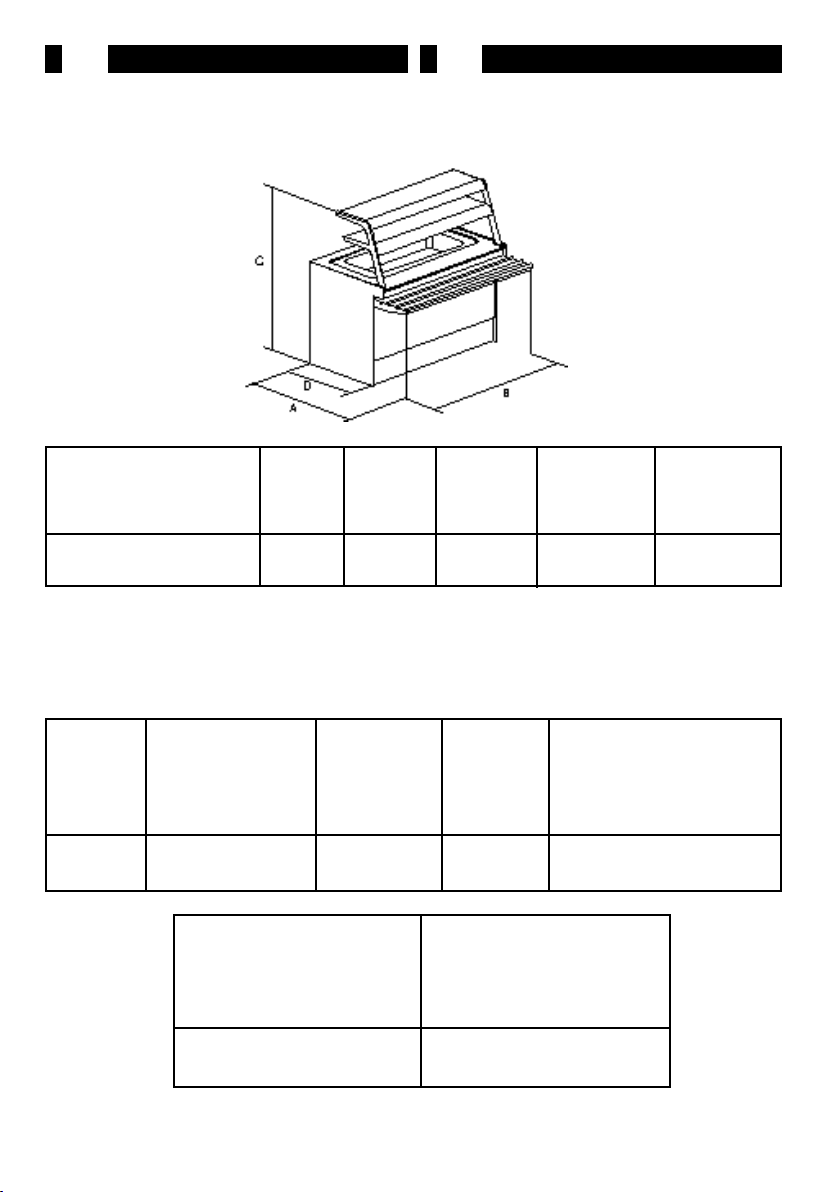
1.6 DIMENSIONI DI INGOMBRO E PESI
I valori sono riportati in tabella 1.
1.6 WEIGHTS AND OVERALL DIMENSIONS
Values are shown in Table 1.
n°4
D (mm)
155
1.7 CARATTERISTICHE TECNICHE
I valori sono riportati in tabella 2
1.7 TECHNICAL DETAILS
All values have been provided in Table 2.
1250
A (mm)
1190
B (mm)
1250
C (mm)
1450 900
Modello
Unit
Modell
Modèle
Peso (kg)
Weight (kg)
Gewicht (kg)
Poids (kg)
Modello
Unit
Model
Modèle
1250
Gas
Gaz
Resa (W)
-10°C+45°C
Potenza
Compressore (Hp)
Compressor Power
Leistung
Puisancecompresseur
1/5 312 R134A 226*
Assorbimento Compressore
(W)
Compressor max. power input
Leistungsaufnahme Kompresor
Absorption Compresseur
Voltaggio
(V)
Voltage
Spannung
Voltage
220V/50Hz +2÷+5
Temperatura di esercizio
(°C)
Working temperature
Betriebstemperatur
Température de service
*Nota: Nel caso vi fosse l'illuminazione della plafoniera (montata a richiesta), la potenza assorbita totale è di 256W

17
FD
1.6 AUSMASSE UND GEWICHTE
Die Werte sind in Tabelle 1 angegeben.
1.6 DIMENSIONS D’ENCOMBREMENT ET POIDS
Les valeurs sont reportées dans le Tableau 1.
1.7 TECHNISCHE MERKMALE
Die Werte sind in Tabelle 2 angegeben.
1.7 CARACTERISTIQUES TECHNIQUES
Les valeurs sont reportées dans le Tableau 2.
18
GB
I
2 INSTALLAZIONE
2.1 TRASPORTO
I piedini della vetrina vengono fatti passare attraverso le
asoledellepiastrediancoraggio chesonomontatesudue
listelli in legno, posizionati in senso longitudinale.
Nella linea team i listelli in legno sono ssati alla struttura
in melaminico del banco mediante chiodi.
la vetrina viene spedita con mezzi di trasporto via terra.
L’imballo normale è costituito da copertura in polietilene,
a richiesta l’azienda fornisce imballi particolari.
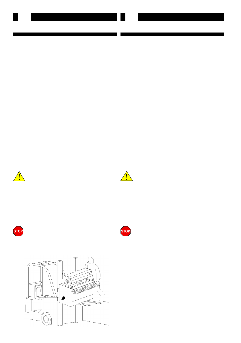
2.2 SOLLEVAMENTO E MOVIMENTAZIONE
Ilcarico elo scaricodellavetrina dai mezziditrasportova
eettuata mediante trans pallet, nella seguente maniera:
- Aancate le forche di questo al livello del mezzo,
- Far scorrere (secondo la lunghezza) la vetrina sopra
le forche del sollevatore no a che questa non risulti in
perfetto equilibrio (n°5).
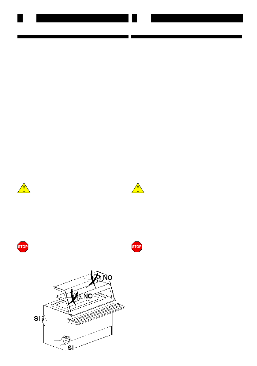
ATTENZIONE!
Non spingere mai la vetrina facendo forza sulle
superci vetrate o sul castello vetri (n°6).
Unavoltaabbassatele forche delsollevatore scaricarlada
queste nella stessa maniera.
La movimentazione della vetrina a terra si eettua a
mano.
Lo scorrimento di questa è facilitato dalla presenza dei
due listelli in legno inferiori.
NOTA:selospostamentodellavetrinadeveessere
fatto successivamente allo scarico si consiglia di
appoggiare la vetrina su due listelli in legno in
modo da favorire l’inserimento delle forche del
sollevatore.
2 INSTALLATION
2.1 TRANSPORT
The display unit feet are passed through the slots in the
anchorage plates which are tted to two wooden strips,
positioned lengthways.
In theTeam line the wood lists are xed to the melaminic
structure of the frame by the mean of spikes.
The unit is normally dispatched over land.
Standardpackagingcomprisespolyethylenecovering.The
Company will provide special packaging on request.
2.2 LIFTING AND HANDLING
Thedisplayunitmustbeunloadedfromitsmeansoftrans-
port using a forklift truck and following this procedure:
- Bring the truck forks level with the transporting ve-
hicle,
- Slide the unit (depending on its length) onto the
forks of the truck and manoeuvre until it is perfectly
balanced (n°5).
CAUTION!
Never use the glass surface as leverage when
pushing the display unit (n°6).
Once the truck forks have been lowered, unload the unit,
sliding it as above.
Oncetheunitison theground, itshouldbemovedmanu-
ally. The unit will slide easily thanks to the two wooden
strips placed on its underside.
NOTE: if, after unloading, the unit is to be
moved at a later stage, we recommend that two
strips of wood be placed underneath it in order
to facilitate the insertion of the truck forks.
n°5
19
FD
2 INSTALLATION
2.1 TRANSPORT
Die Füßchen der Vitrine werden durch die Schlitze der Ver-
ankerungsplatten geführt, die auf zwei Holzleisten, in Läng-
srichtung positioniert, montiert sind.
Bei der Produktlinie Team sind die Holzleisten an der
Thekenstruktur aus Melamin mittels Schrauben befe-
stigt.
Die Vitrine wird normalerweise mit Transportmitteln
auf dem Landweg versandt.
Die normale Verpackung besteht aus einer Schutzhülle aus
Polyäthylen; auf Wunsch liefert die Firma auch Sonderver-
packungen.
2.2 HEBEN UND VERSTELLEN
Das Laden und Abladen der Vitrine von den Transportmitteln
muß mit Hilfe eines Handgabelhubwagens auf folgendeWeise
durchgeführt werden:
-DieGabelndesHandgabelhubwagensunddasTransportmittel
niveaugleich nebeneinanderstellen.
- Die Vitrine (der Länge nach) solange auf die Gabeln des
Handgabelhubwagens schieben, bis sie sich in perfekter
Gleichgewichtslage bendet (Nr.5).
ACHTUNG!
Beim Schieben der Vitrine darf niemals Druck
auf die Glasächen ausgeübt werden (Nr.6).
NachdemdieGabelndesHandgabelhubwagenswiedergesenkt
wurden, wird die Vitrine auf dieselbe Weise abgeladen.
Auf dem Boden wird die Vitrine mit den Händen geschoben.
Das Verstellen wird durch zwei Holzleisten auf der Unterseite
erleichtert.
HINWEIS: soll die Vitrine nach dem Abladen verstellt
werden, wird empfohlen, diese auf zwei Holzleisten
zu stellen, um das Einführen der Gabeln des Handga-
belhubwagens zu erleichtern.
2 INSTALLATION
2.1 TRANSPORT
Les pieds de la vitrine passent à travers les boutonnières des
plaques d’ancrage qui ont été montées sur deux listels en bois,
positionnées dans le sens longitudinal.
Dans la ligne team les listels en bois ont été xés à la structure
de mélamine du comptoir grâce aux clous.
La livraison de la vitrine se fait habituellement à l’aide d’un
moyen de transport par voie terrestre.
L’emballage standard est constitué d’une couverture en
polyéthylène; l’entreprise fournit, sur demande, un emballage
spécique.
2.2 SOULEVEMENT ET DEPLACEMENT
Le chargement et le déchargement de la vitrine des moyens de
transportdoiventêtreeectuésà l’aided’unetranspalette,selon
la procédure suivante:
- Approcher les fourches de la transpalette au niveau du moyen
de transport.
- Faire glisser la vitrine (selon sa longueur) sur les fourches de
l’élévateur jusqu’à ce qu’elle soit en parfait équilibre (n° 5).
ATTENTION!
Ne jamais pousser la vitrine en prenant appui
sur les surfaces vitrées (n° 6)
Après avoir abaissé les fourches de l’élévateur, dégager la
vitrine de ces dernières de la même manière.
Le déplacement au sol de la vitrine doit être eectué ma-
nuellement.Songlissementestfacilitégrâceàla présence
des deux listels inférieurs en bois.
NOTA: si le déplacement de la vitrine doit être
eectué après son déchargement, il est conseillé
de la poser sur deux listels en bois de façon à aider
l’introduction des fourches de l’élévateur.
n°6
20
GB
I
2.3 SPECIFICHE AMBIENTALI
L’operatività della vetrina viene garantita in condizioni
ambientali:
- Temperatura di 25°C
- Umidità relativa di 65%.
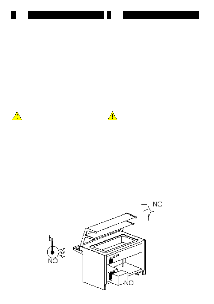
Inoltre nell’installare della vetrina si devrà vericare
che (n°7):
-Vi sia una suciente circolazione d’aria intorno alla
vetrina, ma che non vi siano forti correnti;
- Non la si deve posizionare nelle vicinanze di sorgenti
di aria calda;
- Non deve essere esposta direttamente alla luce del
sole;
- Non devono essere ostruite le griglia per il passaggio
dell’aria di rareddamento del condensatore;
- Non venga indirizzata sulla vetrina l’eventuale aria
condizionata o di riscaldamento del locale .
ATTENZIONE!
E’ essenziale rispettare le indicazioni suddette
per evitare malfunzionamenti, che non saranno
coperti da garanzia.
2.4 POSIZIONAMENTO
Una volta posizionato nella zona desiderata e regolata
l'altezza dei piedini rimuovere i due listelli prima di dare
il posizionamento denitivo. La rimozione dei listelli si
eettua nel seguente modo:
- svitare le viti (n°8 Pos.A) delle piastre di ancoraggio
(n°8 Pos.B);
- sollevare di nuovo la vetrina;
- togliere i due listelli di legno (n°8 Pos.C).
- abbassare la vetrina a terra, posizionarlo nella zona
voluta, avendo cura di coprire il piedino con l'apposita
copertura (n°8 Pos.D).
2.3 AMBIENT CONDITIONS
The display unit is guaranteed to function in the follow-
ing ambient conditions:
- Temperature: 25°C
- Ambient R.H.: 65%
Furthermore, during the installation process, check the
following (n°7):
-That there is sucient air circulation around the display
unit but that there are no strong draughts;
- That the unit is not installed near to sources of hot
air;
- That the unit is not exposed to direct sunlight;
- That the air passage grilles for condenser cooling are
not obstructed in any way;
- That any air conditioning or heating systems are not
directed towards the display unit.
CAUTION!
It is essential to respect the above indications if
malfunctions not covered by the Guarantee are
to be avoided.
2.4 POSITIONING
Once the unit has been positioned as required and
the feet heights have been adjusted, remove the two
wooden strips before xing the unit denitively into
place. The wooden strips are removed as follows:
- Loosen the screws (Pos.A, n°8) of the anchorage plates
(Pos.B, n°8);
- Lift the display unit from the ground;
- Remove the two wooden strips (Pos.C, n°8);
- Lower the unit and position as required, making sure to
cover each foot with the shield provided (Pos.D, n°8).
n°7
Table of contents
Other SIFA Freezer manuals

Popular Freezer manuals by other brands

Dometic
Dometic CoolFreeze CDF-18 operating manual

American Panel
American Panel HurriChill AP3BCF30-1 Installation & user manual

Marvel
Marvel ML24FA Installation, operation and maintenance instructions

Fisher Scientific
Fisher Scientific Isotemp Plus 13-986-142 manual

Mobicool
Mobicool A-40 DC operating manual

Frigidaire
Frigidaire FFC05M0AW Factory parts catalog


