Sifam Tinsley Alpha 45 User manual

Rev. A 11/2014
Operating Manual
IC:2-60-006-00-00531
Alpha 45
L1
L2
L3


Section Contents
1. Introduction
2. Measurement Reading Screen
4. Programming
4.1 Password Protection
4.2 Menu selection
4.2.1 System Parameter selection screen
4.2.2 Communication Parameter selection screen
4.2.3 Reset Parameter selection screen
4.2.4 Relay Output parameter selection screen
4.2.1.1 System type
4.2.1.2 Potential transformer Primary value
4.2.1.3 Potential transformer secondary value
4.2.1.4 Current transformer Primary value
4.2.1.5 Energy Display on modbus
4.2.1.6 Energy Digit Rollover(reset) count
4.2.2.1 Address Setting
4.2.2.2 RS 485 Baud rate
4.2.2.3 RS 485 Parity selection
4.2.3.1 Resetting Parameter
4.2.4.1 Pulse Duration (width) selection
3. Phase Indications
Alpha 45
Installation & Operating Instructions
Three Phase Energy Meter
3

4.2.5 Quit screen
10. Specification
Installation
8.1 EMC Installation Requirements
8.2 Case Dimensions and Panel Cut-out
8.3 Wiring
8.4 Auxiliary Supply
8.5 Fusing
8.6 Earth / Ground Connections
9.
11. Connection for Optional Pulse output / RS 485
8.
Phaser Diagram
7.
6. RS 485 (Modbus) Output
5. Relay Output (Optional).
4.2.4.2 Pulse rate divisor
6.1 User assignable Modbus Register
Network Wiring
5.1 Pulse Output
4
1. Introduction
The instrument is a panel mounted 96 x 96mm DIN Quadratic energy meter. It accumulates
Active energy, in three phase network.
The instrument also measures AC Voltage, AC Current, Frequency, Power, Power factor,
Phase Angle, Apparent Energy which can be accessed via Modbus. All voltage & Current
measurements are True RMS upto 15th harmonic.
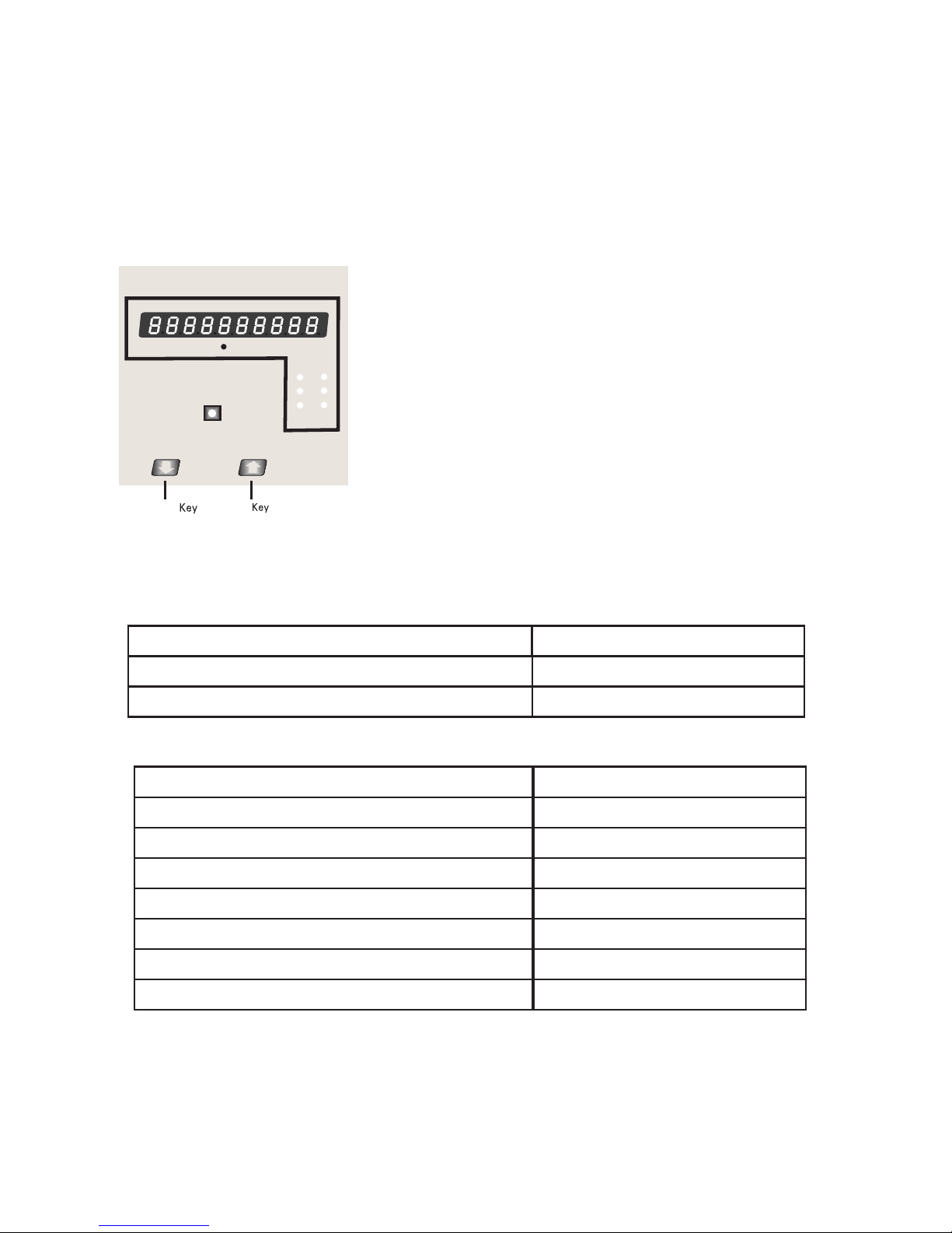
Ultra high brightness LED display.
Down Up
It can be configured & Programmed at site for the
following :
PT Primary, PT Secondary 3 phase 3W or 3 Phase
4W system.
The front panel has two push buttons through which the
user can reset the energy & configure the product.
The front panel has Impulse red led, flashing at rate
proportional to measured power.
Its impulse rate is 3600impulses/kWh.
x1000 kWh
VON
L1
L2
L3
IREV
3600 Imp/KWh
Measured Parameters Units of measurement
TABLE 1:
Display Parameter
Active Energy (8 digit counter) kWh
System Voltage
System Current
Voltage VL1-N(4wire only)
Voltage VL2-N(4wire only)
Voltage VL3-N(4wire only)
Voltage VL1-L2
Volts
Amps
Volts
Volts
Volts
Volts
Modbus Parameter (Optional)
Units of measurement
Measured Parameters
5
Voltage VL2-L3
Voltage VL3-L1
Current L1
Volts
Volts
Amps
Current L2 Amps
Frequency
Current L3
Active Energy
Hz
kWh
Apparent Energy
Active Power (System / Phase (4 wire only) )
Reactive Power (System / Phase )(4 wire only)
Apparent Power (System / Phase )(4 wire only)
Power Factor (System / Phase )(4 wire only)
Phase Angle (System / Phase (4 wire only))
Kwatts
KVAr
KVA
Degree
kVAh
Amps
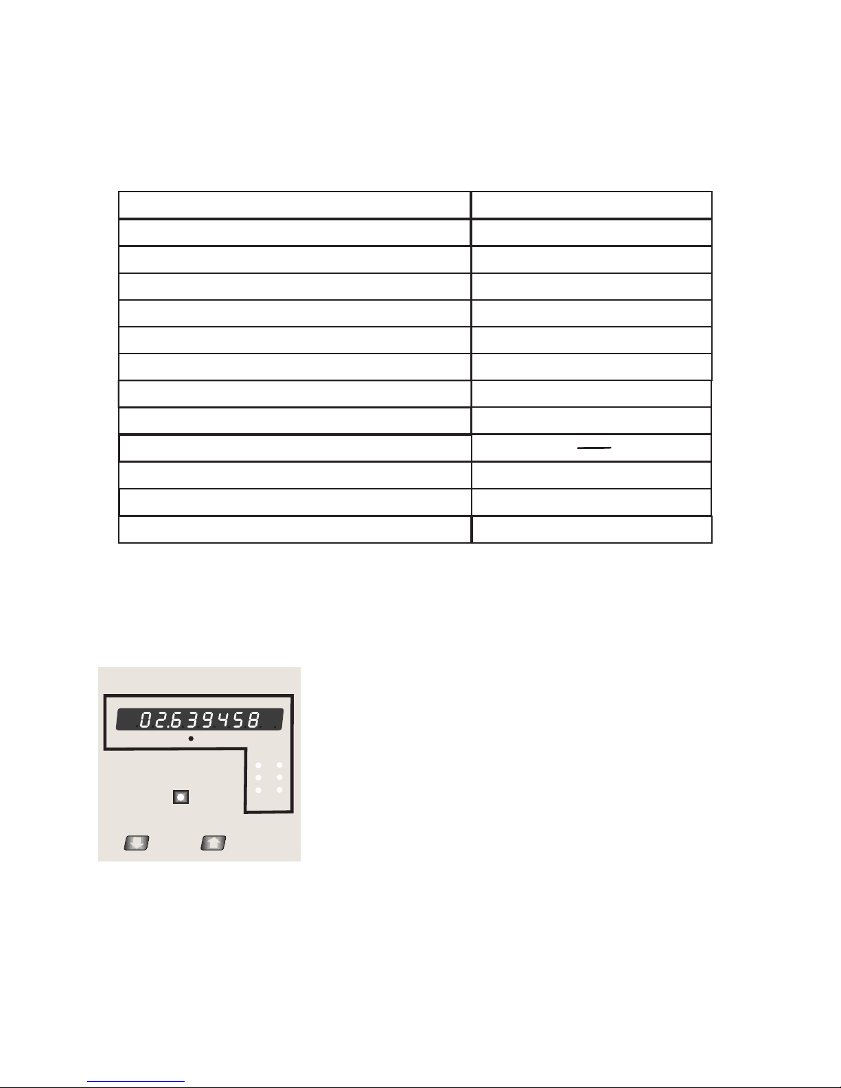
2. Measurement Reading Screen
In normal operation the user is presented with active energy measurement screen.
Screen 1 : Active Energy (kWh)
x1000 kWh
VON
L1
L2
L3
IREV
3600 Imp/KWh
6
When x1000 LED glows the energy is displayed in mega watt.
Active energy is displayed in 8 digit counter with auto ranging feature. Below given table
describes auto ranging with minimum resolution of energy measured in perticular range.
Display Format X1000 LED Minimum resolution
99.999999
999.99999
9999.9999
99999.999
999999.99
9999999.9
99999999
999999.99
9999999.9
99999999
OFF
OFF
OFF
OFF
OFF
OFF
OFF
ON
ON
ON
1 miliWatt
10 miliWatt
100 miliWatt
1 Watt
10 Watt
100 Watt
1 kiloWatt
10 kiloWatt
100 kiloWatt
1 MegaWatt
Maximum Active energy count reached is 99999999 MegaWatt after this counter rollovers
to zero and measurement starts from first range.
Impulse led on front panel can be used to cross check the energy calibration on site.
Its nominal impulse rate is 3600 impulses / kWh.
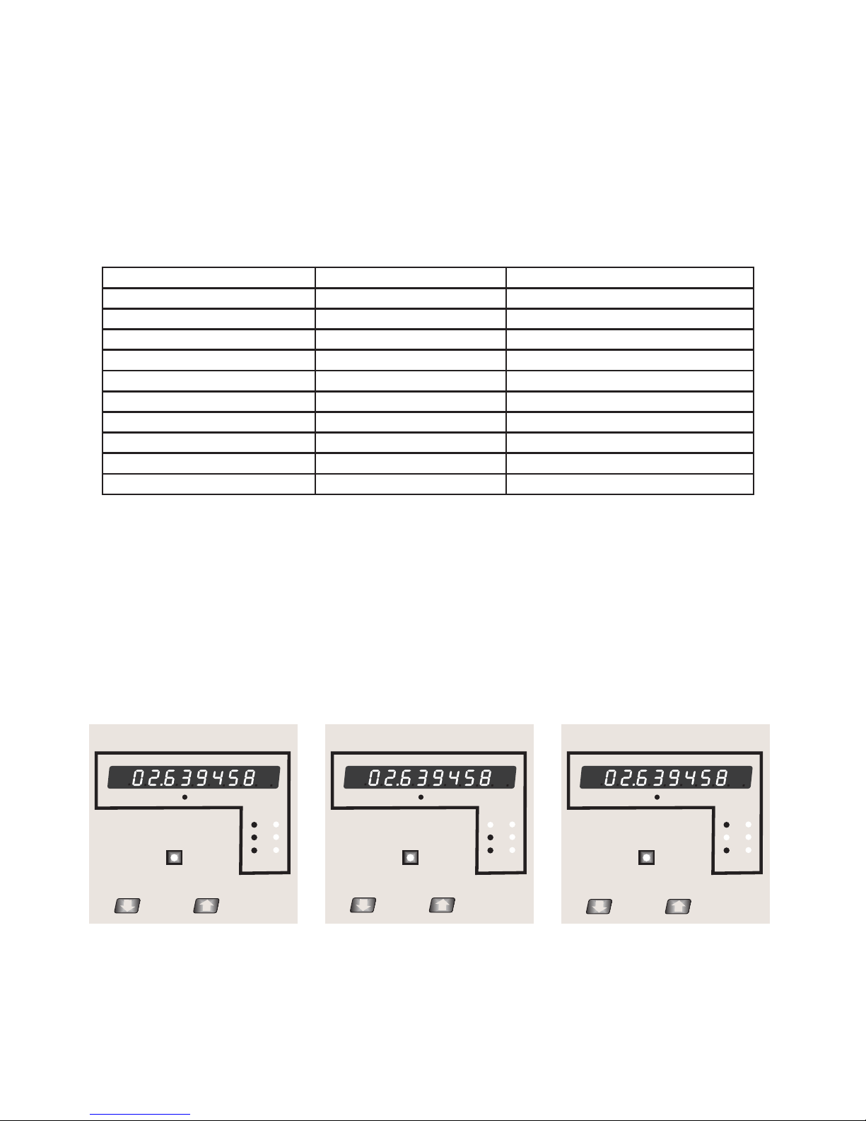
3. Phase Indications
x1000 kWh
VON
L1
L2
L3
IREV
3600 Imp/KWh
“LED Von (L1, L2, L3) glowing”
All three phase (L1, L2, L3) present
“LED Von(L1) off & Von(L2, L3) glowing”
L1 phase absent & L2, L3 phase present
“LED Von(L2) off & Von(L1, L3) glowing”
L2 phase absent & L1, L3 phase present
7
x1000 kWh
VON IREV
3600 Imp/KWh
L1
L2
L3
x1000 kWh
VON
3600 Imp/KWh
IREV
L1
L2
L3
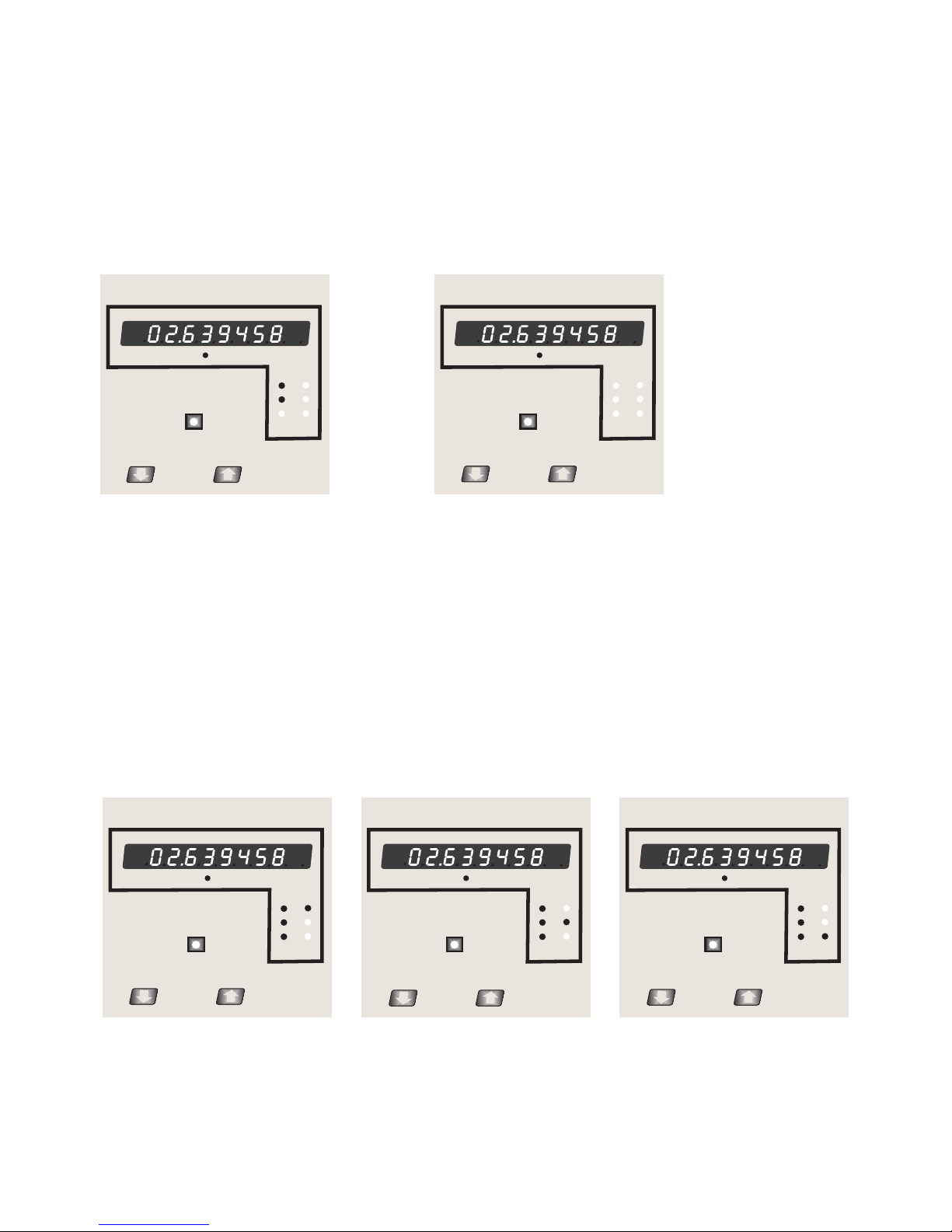
“LED I (L3) glowing”REV
L3 phase current reverse
8
“LED Von(L3) off & Von(L1, L2) glowing”
L3 phase absent & L1, L2 phase present
“LED Von(L1,L2,L3) off ”
L1,L2,L3 phase absent
x1000 kWh
VON
L1
L2
L3
IREV
3600 Imp/KWh
x1000 kWh
VON
L1
L2
L3
IREV
3600 Imp/KWh
Phase sequence error
If all the three LEDs Von(L1,L2,L3) start blinking, it indicates all the
three phases are present but phase sequence error has occurred.
If phase sequence is or L2-L3-L1 L1-L2-L3 or L2-L3-L1 then it is
condition. But if sequence is L1-L3-L2 healthy or L2-L1-L3 or
sequence is connected to any other irregular to meter then it
sequence error.indicates phase
x1000 kWh
VON
L1
L2
L3
IREV
3600 Imp/KWh
“LED I (L1) glowing”REV
L1 phase current reverse
“LED I (L2) glowing”REV
L2 phase current reverse
x1000 kWh
VON IREV
3600 Imp/KWh
L1
L2
L3
x1000
3600 Imp/KWh
kWh
VON IREV
L1
L2
L3

“LED I (L1, L2, L3) glowing”REV
L1, L2, L3 phase current reverse
x1000 kWh
VON
L1
L2
L3
IREV
3600 Imp/KWh
9
SEL (Select)
A
: UP KEY
: DOWN KEY
(Select Relay Parameter)
quit
(Exit Menu)
Exit from setup Parameter to Main Display
rESEt
(Reset Parameter)
non
(No
Parameter),
E (Energy),
“Down” key
SEriAL
(
Serial Communication
)
Add
(Modbus Address)
br
(Baud Rate)
Pr
(Parity Bits)
cd (PassWord)
SEL
(Select System
Parameter)
(Sec 4.2.2)
SYS
(System Type / Network)
UP
(PT Primary)
(Sec 4.2.1.1)
(Sec 4.2.1.2)
Setup Parameter Screen
(Sec 4.2.5)
Parameter
(Sec 4.2.2.1)
(Sec 4.2.2.2)
(Sec 4.2.2.3)
(Sec 4.2.3)
SYS
(Sec 4.2.1)
SEL
SEL
(Sec 4.2.4)
rELAY
SEL
dur
(Relay Pulse Duration)
rAt
(Pulse Rate Divisor)
(Sec 4.2.4.1)
(Sec 4.2.4.2)
AP
(CT Primary)
(Sec 4.2.1.4)
US
(PT Secondary)
(Sec 3.2.1.3)
(Sec 4.2.3.1)
A
EnO
Edr
(Energy digit reset count)
(Sec 4.2.1.5)
(Energy Display on ModBUS)
(Sec 4.2.1.6)
A
4.1. Password Protection
Password protection can be enabled to prevent unauthorised access to set-up screens,
by default password protection is not enabled.
Password protection is enabled by selecting a four digit number other than 0000, setting a
password of 0000 disables the password protection.
x1000 kWh
VON
L1
L2
L3
IREV
3600 Imp/KWh
4. Programming
The following sections comprise step by step procedures for configuring the meter for
individual user requirements.
To access the set-up screens press and hold the “ Down” and “ Up” Key simultaneously
for 5 seconds. This will take the User into the Password Protection Entry Stage (Section 4.1).
x1000 kWh
VON
L1
L2
L3
IREV
3600 Imp/KWh
10

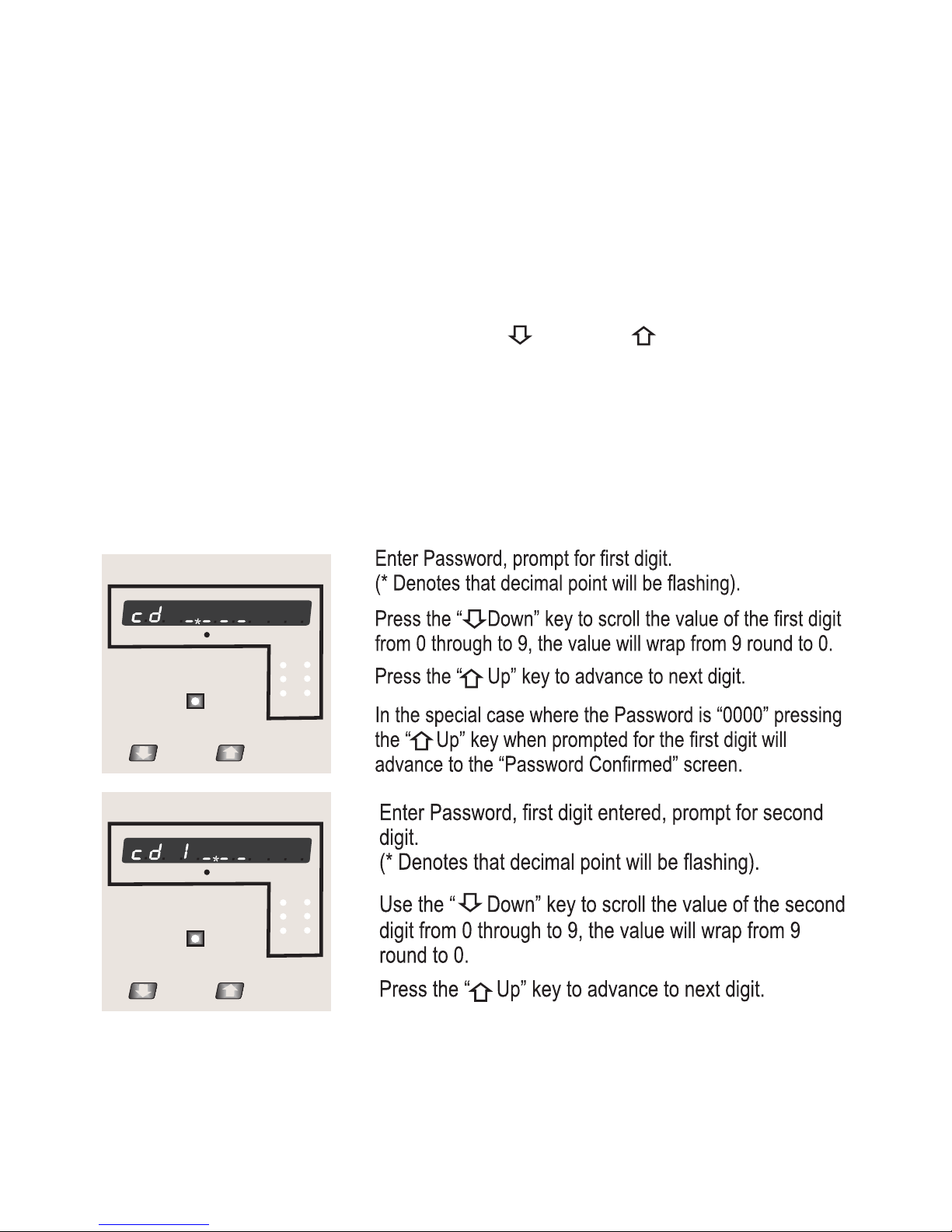
Enter Password, second digit entered, prompt for third
digit.
(* Denotes that decimal point will be flashing).
Use the “ Down” key to scroll the value of the third
digit from 0 through to 9, the value will wrap from 9
round to 0.
Press the “ Up” key to advance to next digit.
x1000 kWh
VON
L1
L2
L3
IREV
3600 Imp/KWh
Enter Password, third digit entered, prompt for fourth
digit.
(* Denotes that decimal point will be flashing).
Use the “ Down” key to scroll the value of the fourth
digit from 0 through to 9, the value will wrap from 9
round to 0.
Press the “ Up” key to advance to verification of the
password.
Enter Password, fourth digit entered, awaiting
verification of the password.
x1000 kWh
VON
L1
L2
L3
IREV
3600 Imp/KWh
x1000 kWh
VON
L1
L2
L3
IREV
3600 Imp/KWh
11
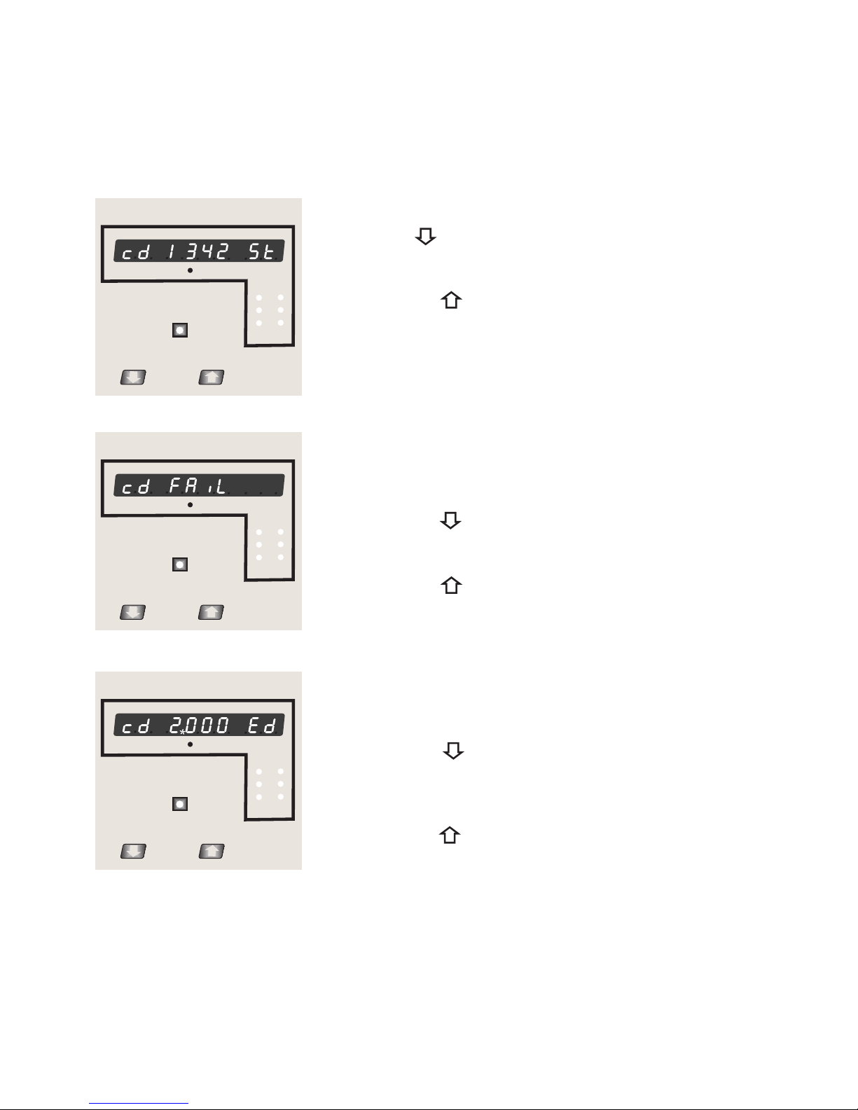
Password confirmed.
Pressing “ Down” key will advance to the “New /
change Password” entry stage.
Pressing the “ Up” key will advance to the Menu
selection screen. (See section 4.2).
Password Incorrect.
The unit has not accepted the Password entered.
Pressing the " Down" key will return to the Enter
Password stage.
Pressing the “ Up” key exits the Password menu and
returns operation to the measurement reading mode.
x1000 kWh
VON
L1
L2
L3
IREV
3600 Imp/KWh
x1000 kWh
VON IREV
3600 Imp/KWh
New / Change Password
(*Decimal point indicates that this will be flashing).
Pressing the “ Down” key will scroll the value of the
x1000 kWh
VON IREV
3600 Imp/KWh
first digit from 0 through to 9, the value will wrap from 9
round to 0.
Pressing the “ Up” key to advance the operation to
the next digit and sets the first digit, in this case to “2”
12
L1
L2
L3
L1
L2
L3

x1000 kWh
VON IREV
3600 Imp/KWh
13
New / Change Password, first digit entered, prompting
for second digit. (*Decimal point indicates that this will
be flashing).
Pressing the “ Down” key will scroll the value of the
second digit from 0 through to 9, the value will wrap
from 9 round to 0.
Pressing the “ Up” key to advance the operation to
the next digit and sets the second digit, in this case to “1”
x1000 kWh
VON IREV
3600 Imp/KWh
New / Change Password, second digit entered,
prompting for third digit. (*decimal point indicates that
this will be flashing).
Pressing the “ Down” key will scroll the value of the
third digit from 0 through to 9, the value will wrap from
9 round to 0.
Pressing the “ Up” key to advance the operation to
the next digit and sets the third digit, in this case to “5”
x1000 kWh
VON IREV
3600 Imp/KWh
New / Change Password, third digit entered, prompting
for fourth digit. (* denotes that decimal point will be
flashing).
Pressing the “ Down” key will scroll the value of the
fourth digit from 0 through to 9, the value will wrap from
9 round to 0.
Pressing the “ Up” key to advance the operation to
the “New Password Confirmed” and sets the fourth digit,
in this case to “3”.
L1
L2
L3
L1
L2
L3
L1
L2
L3

14
New Password confirmed.
Pressing the “ Down” key will return to the
“New/ChangePassword”.
Pressing the “ Up” key will advances to the Menu
selection screen.(see section 4.2).
x1000 kWh
VON IREV
3600 Imp/KWh
4.2 Menu selection.
This menu screen is used to select the different system
Parameter like “system type,””CT Ratio”,”PT Ratio”,
Pressing the “ Up” key allows the user to set
Pressing the “ down” key will advance to
Different system parameters.
Communication selection screen (see section 4.2.2)
4.2.1 System Parameter selection screen.
(see section 4.2.1.1 to 4.2.1.5)
x1000 kWh
VON IREV
3600 Imp/KWh
4.2.2 Communication Parameter selection screen.
This menu screen is used to select the different
communication parameters like “Address selection”,
”Rs485 Parity selection”, ”RS485 baud rate”
kWh
x1000
VON IREV
3600 Imp/KWh
Pressing the “ Up” key allows the user to set different
Pressing the “ down key will advance to Reset parameter
Communication parameters
(see section 4.2.3)
Screen.
(see section 4.2.2.1 to 4.2.2.3)
L1
L2
L3
L1
L2
L3
L1
L2
L3

15
4.2.3 Reset Parameter selection screen.
This menu screen is used to Reset the energy parameter .
Pressing the “ Up” key allows the user to Reset energy
Pressing the “ down key ” will advance to Output
system parameter (see section 4.2.3.1)
Option selection screen (see section 4.2.4).
x1000 kWh
VON IREV
3600 Imp/KWh
This menu screen will allow the user to select different
Parameter related to Relay Output.
Pressing the “ Up” key allows the user to select &
Configuare the relay output option (see section 4.2.4.1)
(see section 4.2.5)
Pressing the “ down key will advance to Quit screen.
4.2.4 Relay Output Parameter selection screen.
x1000 kWh
VON IREV
3600 Imp/KWh
4.2.5 Quit screen.
Pressing the “ Up” key will allow the user to Quit
from menu & return to measurement screen.
This screen allows user to Quit from Menu.
x1000 kWh
VON IREV
3600 Imp/KWh
4.2.1)
L1
L2
L3
L1
L2
L3
L1
L2
L3
x1000 kWh
VON IREV
3600 Imp/KWh
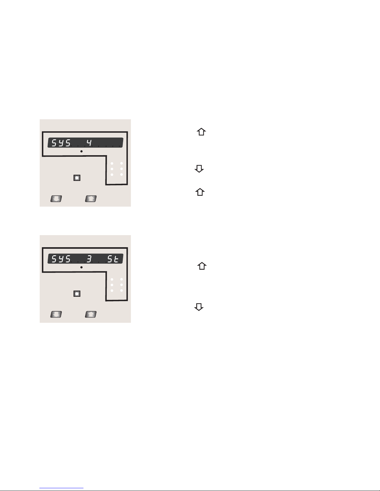
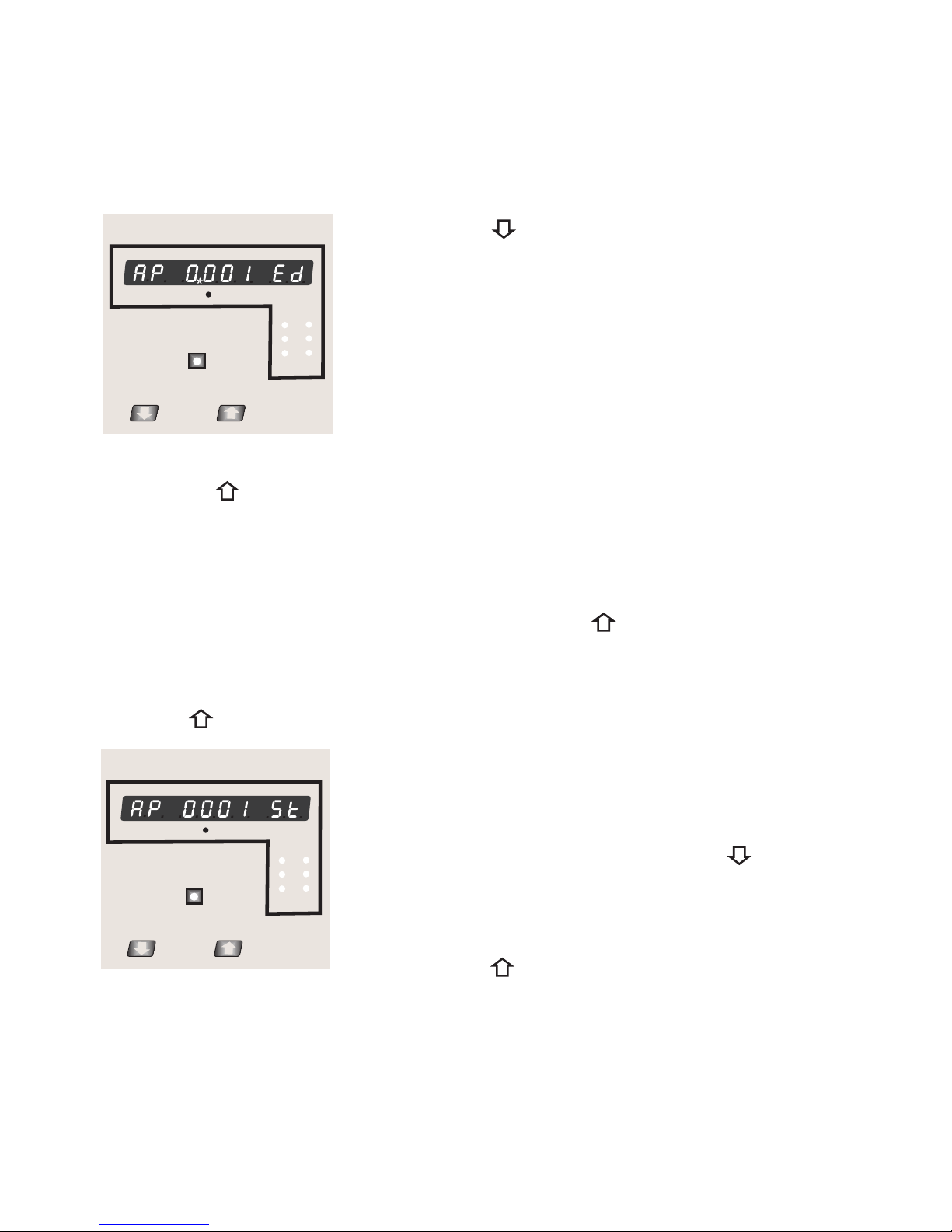
4.2.1.1 System Type
4.2.1 System parameters Selection
This screen is used to set the system type. System type
”3” for 3 phase 3 wire & “4” for 3 phase 4 wire system.
type confirmation menu.
Pressing the “ Up” key accepts the present
primary value Edit” menu (see section 4.2.1.2)
value and advances to the “Potential transformer
Pressing the “ Down” key will enter the system type
edit mode and scroll the values through values available .
Pressing the “ Up” key advances to the system
x1000 kWh
VON IREV
3600 Imp/KWh
System Type Confirmation
This screen will only appear following the edit of
system type. If system type is to be changed again,
Pressing the “ Down” key will return to the system type
edit stage by blanking the bottom line of the display
Pressing the “ Up” key sets the displayed value and
will advance to “Potential Transformer Primary Value
Edit” menu. (See section 4.2.1.2)
4.2.1.2 Primary Value Potential Transformer
The nominal full scale voltage which will be displayed as the L1-N, L2-N and L3-N for a
four wire (Ln) system or as L1-2, L2-3 and L3-1 in a three wire(LL) system. This screen
enables the user to display the line to neutral and line to line voltages inclusive of any
transformer ratios, the values displayed represent the voltage in kilovolts (note the x1000
enunciator).
16
L1
L2
L3
L1
L2
L3

Pressing the “ Up” key accepts the present value
and advances to the “potential Transformer secondary
Value edit” menu. (See Section 4.2.1.3)
Pressing the “ Down” key will enter the “Potential
Transformer Primary Value Edit” mode.
Initially the “multiplier must be selected, pressing the “
Down” key will move the decimal point position to the
right until it reaches # # # .# after which it will return to
#. # # #.
Pressing the “ Up” key accepts the present multiplier (decimal point position) and
advances to the “potential Transformer primary Digit Edit” mode.
Potential Transformer primary Digit Edit
Pressing the “ Down” key will scroll the value of
the most significant digit from 0 through to 9 unless
the presently displayed Potential Transformer Primary
Value together with the Current Transformer Primary
Value, previously set, would result in a maximum power
of greater than 1000 MVA per phase in which case
the digit range will be restricted.
Pressing the “ Up” key accepts the present value at the cursor position and advances
the cursor to the next less significant digit.
x1000 kWh
VON IREV
3600 Imp/KWh
x1000 kWh
VON IREV
3600 Imp/KWh
Note : the flashing decimal point indicates the cursor position, a steady decimal point will
be present to identify the scaling of the number until the cursor position coincides with the
steady decimal point position. At this stage the decimal point will flash.
When the least significant digit has been set pressing the “ Up” key will advance to the
“Potential Transformer Primary Value Confirmation” stage.
17
L1
L2
L3
L1
L2
L3
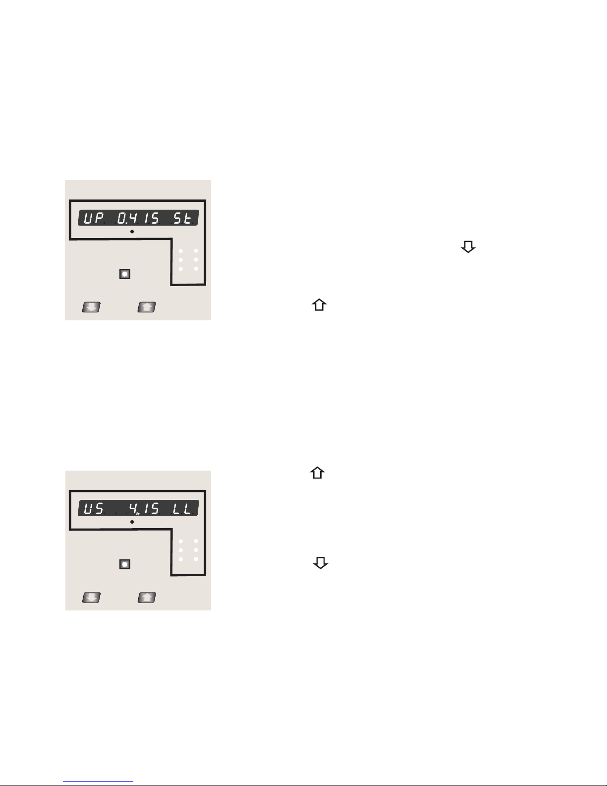
Screen showing display of 0.415 kV i.e. 415 Volts indicating steady decimal point and cursor
flashing at the “hundreds of volts” position.
for 3W
L-L
Note : 0.120 kV i.e. 120 V for 4W
L-N
120 V
Potential Transformer Primary Value Confirmation
This screen will only appear following an edit of the
Potential Transformer Primary Value.
If the scaling is not correct, pressing the “ Down”
key will return to the “Potential Transformer Primary
Value Edit” stage.
Pressing the “ Up” key sets the displayed value
and will advance to the Potential Transformer secondary
Value (See Section 4.2.1.3)
x1000 kWh
VON IREV
3600 Imp/KWh
4.2.1.3 Potential Transformer secondary Value
The value must be set to the nominal full scale secondary voltage which will be obtained
from the Transformer when the potential transformer(PT)primary is supplied with the voltage
defined in 4.2.1.2 potential transformer primary voltage.The ratio of full scale primary to full
scale secondary is defined as the transformer ratio.
Note that the range of instrument is from 140 to 277V
Transformer Secondary Value Edit” mode.
Down” key will scroll the value of the most significant digit
From available range of PT secondary value
Pressing the “ Down” key will enter the “Potential
Pressing the “ Up” key accepts the present value
and advances to the “Current Transformer Primary
Value edit” menu. (See Section 4.2.1.4)
for 239 VL-N. Please refer the table below for different ranges.
x1000 kWh
VON IREV
3600 Imp/KWh
18
L1
L2
L3
L1
L2
L3

Pressing the “ Up” key accepts the present value at the cursor position and advances
the cursor to the next less significant digit.
Potential Transformer Secondary Value Confirmation
This screen will only appear following an edit of the
Potential Transformer Value.Secondary
If the scaling is not correct, pressing the “ Down”
key will return to the “Potential Transformer Secondary
Value Edit”
Pressing the “ Up” key sets the displayed value
and will advance to the current Transformer Primary Value (See Section 4.2.1.4)
Note : the flashing decimal point indicates the cursor position, a steady decimal point will
be present to identify the scaling of the number until the cursor position coincides with the
steady decimal point position. At this stage the decimal point will flash.
When the least significant digit has been set pressing the “ Up” key will advance to the
“Potential Transformer secondary Value Confirmation” stage.
Potential Transformer secondary ranges for various Input Voltages
110V L-L (63.5V L-N) 100 - 120V L-L (57V - 69V L-N)
121 - 239V L-L (70V - 139V L-N)
240 - 480V L-L (140V - 277V L-N)
230V L-L (133.0V L-N)
415V L-L (239.6V L-N)
x1000 kWh
VON IREV
3600 Imp/KWh
4.2.1.4 Current Transformer Primary Value
The nominal Full Scale Current that will be displayed as the Line currents. This screen
enables the user to display the Line currents inclusive of any transformer ratios, the values
displayed represent the Current in Amps.
Pressing the “ Up” key accepts the present value and rollbacks to menu selection screen
(See Section 4.2)
19
L1
L2
L3
20
restricted, the value will wrap. Example: If primary value
of PT is set as 400kV (max value) then primary value of Current is restricted to 1736A.
Pressing the “ Up” key will advance to the next less significant digit. (* Denotes that
decimal point will be flashing).
Pressing the “ Down” key will enter the “Current
Transformer Primary Value Edit” mode. This will scroll the
value of the most significant digit from 0 through to 9,
unless the presently displayed Current Transformer
Primary Value together with the Potential Transformer
Primary Value results in a maximum power of greater
than 1000 MVA in which case the digit range will be
when the “ Up” key is pressed.
The “Maximum Power” restriction of 1000 MVA refers to 120% of nominal current and 120%
of nominal voltage, i.e, 694.4 MVA nominal power per phase.
When the least significant digit had been set, pressing the “ Up” key will advance to the
“Current Transformer Primary Value Confirmation” stage.
The minimum value allowed is 1, the value will be forced to 1 if the display contains zero
Current Transformer Primary Value Confirmation.
This screen will only appear following an edit of the
.
If the scaling is not correct, Pressing the “ Down” key
will return to the “ Edit
stage with the most significant digit highlighted (associated
decimal point flashing).
Current
Transformer Primary Value
Current Transformer Primary Value
x1000 kWh
VON IREV
3600 Imp/KWh
x1000 kWh
VON IREV
3600 Imp/KWh
”
Pressing the “ Up” key sets the displayed value and
will advance to the “Energy Display on Modbus” menu.(See section 3.2.1.5)
L1
L2
L3
L1
L2
L3
Table of contents
Other Sifam Tinsley Measuring Instrument manuals


