SIFER 994725MF User manual

Integriti/Inception SIFER Keypad Smart Card Reader. Installation Manual. Revision 1.0 May. 2017.
Integriti/Inception
SIFER Keypad Reader
P/N: 994725MF (Multi-format)
994725 (Standard)
Overview
The SIFER Keypad features an attractive design with a
backlit, ergonomic keypad and an optical tamper device to
alarm the relevant “Reader Fault” System Input on removal
from the mounting surface.
The RGB LEDs allow configurable colour, and in an
Integriti or Inception system the 2nd LED and beeper can be
used in a variety of configurations for Valid/Invalid indication,
Door/Area status, DOTL annunciation, Alarm condition, etc.
The standard Reader supports 13.56MHz SIFER Cards
utilizing MIFARE®DESFire®EV1 with AES encryption.
The Multi-format version also reads CSN or UID data from
other 13.56MHz formats including MIFARE Classic®, Mini,
Ultralight®, Plus®& JCOP; Felica JIS & NFC; ISO15693;
Type B and Picopass. Refer to the latest SIFER Smart Card
Reader Data Sheet for full details of the formats supported.
Connection to the host Module is via multi-drop RS485
cabling. Up to 16 Readers can be connected on the same
Reader bus. Communication is via industry standard OSDP
allowing compatibility with other Controllers and bus sharing
with other manufacturer’s OSDP devices.
In Integriti/Inception systems, Readers can be automatically
addressed & have firmware updated over the system wiring.
Integriti compatability.
Parts List: - Reader body with integrated pigtail cable.
- Mounting plate.
- Countersunk screw.
- Installation manual. (This document)
Extending Cable
See “Preliminary Installation Notes 3 & 4” on page 2.
The pigtail cable can be extended with twisted-pair multistrand
data cable. Pair 1 for Data A/B; Pair 2 for V+/0V. Shielded
cable provides additional noise immunity. RS485/RS422 data
cable, balanced data cable and multistrand UTP cable are
recommended. Specific recommendations are provided below.
READER POWER: Remember to allow for voltage drop on
V+/0V over longer distances and/or when Readers are wired in
a daisy chain (multi-drop) configuration. Supply voltage drop
on the cable is approx. 17mV per metre per Reader using 7/0.2
(24AWG) cable and assuming each Reader draws 100mA.
OVERALL SHIELD (2Pair)
Tycab. DPF4702 or DCK4702 Belden. 9842
Electra. EAS7202P or EAS7302P Garland. MCP-2S
General Cable. B2002CS Alpha. 6413
Roadworx. RW600224 Olex. JD2PS485A
OVERALL SHIELD (3Pair)
Belden. 9843 Tycab. DPF6702
General Cable. B2003CS Garland. MCP-3S
Electra. EAS7203P Electra. EAS7303P
INDIVIDUALLYSHIELDED PAIRS (2 Pair)
Tycab. DQQ47025 Garland. MCP-2IS
Alpha. 2466C Belden. 8723
UTP
Garland UTPL5EMTP (4 Pair stranded UTP patch cable)
If you have a requirement to use other cable types (e.g. short
runs of non-twisted cable), please contact Inner Range
Technical Support for advice.
Specifications
Environment: Operating Temp: -35°C to +65°C.
Ingress Protection: IP67
Physical dimensions. H: 105mm W: 62mm D: 18mm
Mounting plate. 103 mm (H) x 60 mm (W)
Power supply input: 11-14V DC <500mV ripple.
Current consumption: 75 - 115mA typical. 165mA max.
*Depends on LED configuration.
Maximum Cabling Distance using recommended cables.
Data (Data A/Data B/0V).
Access Module to furthest Reader: 1000m.
Total data cabling on one “RDR RS485” Port: 1000m.
Power (V+/0V). @100mA* per Reader.
To 1 Reader using 2-Pair 7/0.2 cable: 100m.
To 1 Reader using 2-Pair 14/0.2 cable: 200m.
To 2 Readers using 3-Pair (2 pairs for +V/0V) 100m.
For longer cable runs &/or multiple Readers on the same
run, one of the following may be required:
- Heavier duty 2-pair cable.
- Additional pair or separate heavy duty fig. 8 for +V/0V.
- A separate battery-backed local power supply.
See “READER POWER” below for more details.
Note: Integriti Module programming (IAC/ILAM/SLAM)
For PIN Code operations (Card And PIN / Card Or PIN / PIN
Only); Under ‘Readers’ ensure that ‘PIN Mode’ is “SIFER/
OSDP/Motorola”. The ‘PIN device’option is left blank.
P 1
tcudorPnoisreV.niMeludoMrepsredaeRREFIS
CAI/CSIretalro10.61V)YLNOCAI(61
MALIretalro0.2V61
MALSretalro0.2V4
erawtf
oSitirgetnIretalro0.61Va/n
Due to on-going product development this manual is subject
to change without notice. www.innerrange.com.au
© 2017. Inner Range Pty. Ltd. Doc. Part No: 634725
Inner Range recommends installing the latest firmware.
Integriti/Inception SIFER Keypad Smart Card Reader. Installation Manual. Revision 1.0 May. 2017.
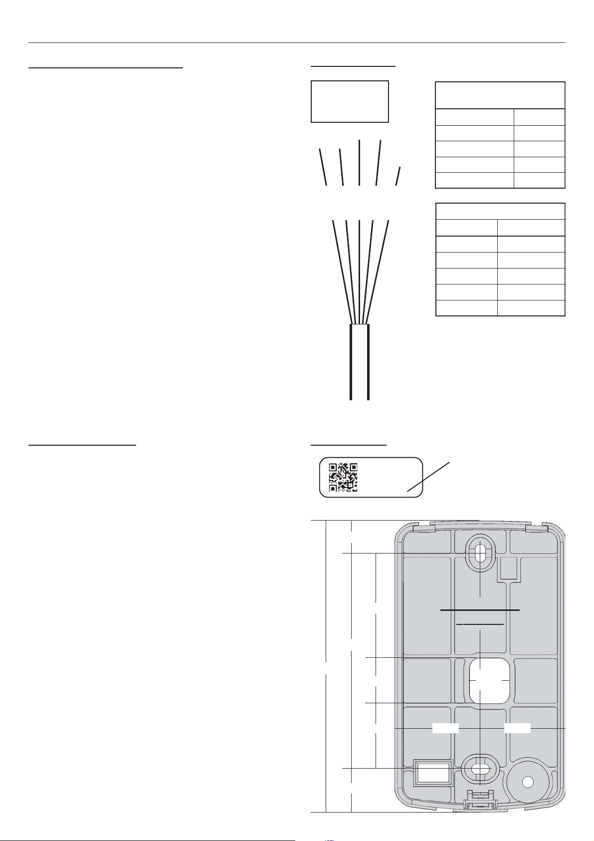
V+
0V
A
B
Red
Black
White
Green
Orange Factory use only.
Not used in the field.
Preliminary Installation Notes
1. MOUNTING SURFACE. The SIFER Reader is optimized
for mounting on a non-metallic surface. A metallic surface
will cause a small decrease in the read range.
To extend the read range when mounted on a metallic
surface, a non-metallic mounting block may be used.
2. IN/OUT READERS. If two SIFER Readers are installed
back to back on either side of a Door, mount the Readers at
different heights to minimize interference.
3. CABLING. SIFER Readers are wired in a star and/or
daisy-chain configuration from the “RDR RS485” Port,
within the limits defined under Specifications on page 1.
The pigtail cable can be extended using twisted pair cable.
2-pair, 7/0.20 twisted pair data cable is recommended.
See “Wiring Diagram” opposite.
See “Specifications” and “Extending Cable” on page 1 for
cabling distances and recommended cables.
If the cable has more than 2 Pairs, a spare pair may also be
connected in parallel to V+ & OV to reduce voltage drop.
4. SHIELDED CABLE. If shielded cable is used:
a) Do NOT use the shield as the 0V (negative) connection
or allow the shield to contact other wiring or metalwork.
b) Shield is terminated to a protective earth (if available) or
0V, at one end of the cable. i.e. At the host Module.
5. Make a note of the Serial number of each Reader & where
it will be installed. See “Serial Number” opposite.
‘RDR RS485’
or
‘READER’
Mounting Plate
Template
14mm
To extend the length of the Reader pigtail
cable, twisted pair cable is used as
follows:
Pair 1. DataA and Data B
Pair 2. V+ and 0V.
See Preliminary Installation Notes 3 & 4.
DILANIMRETELUDOM 'REDAER'/'584SRRDR'
epyTeludoMDIBCP
CAIitirgetnI7T
MALIitirgetnI1T
MALSitirgetnI1T
.tnoCnoitpe
cnIREDAER
SNOITCENNOCREDAER
ruoloCesopruP
deRylppusV21+
kcalBylppusV0
etihWAataD
neerGBataD
egnarOylnoyrotcaF
Reader Cable.
Installing the Reader
1. Mount the SIFER Keypad on a flat, solid surface at an
appropriate height for easy keypad use. Determine the
mounting location and ensure that cable access is available.
2. If the mounting plate is attached to the body of the Reader,
remove it. Insert a small flat blade screwdriver into one of
the two rectangular slots at the bottom rear of the Reader
and gently lift the mounting plate out of the Reader body.
3. Using the mounting plate, or the template opposite, mark
out, then drill holes for the 2 mounting screws and the cable
entry at the mounting location, then secure the mounting
plate to the surface using appropriate hardware.
4. Join the extending cable (if required) to the Reader pigtail
cable using appropriate terminals/joiners. Note the wire
colours (as they may be different), then route the cable
from the mounting location to the Access Module.
5. Fit off the cable to the Access Module “RDR RS485”
terminal as shown above opposite.
6. Test the installation, then fit the Reader body to the
mounting plate as follows:
a) Position the tabs in the top of the Reader body into the
slots at the top of the mounting plate.
b) Push the bottom of the Reader body onto the mounting
plate until it clicks into place.
c) Secure the body to the mounting plate at the bottom of
the assembly with the countersunk screw provided.
P 2
Wiring Diagram
Serial Number
The Serial number is the
bottom line of digits on the
label affixed to the top rear
of the Reader.
964725-
091116-
00-
000019
11.5mm
37mm
76mm
102.7mm 16mm
23mm
15.2mm
30mm 30mm
This manual suits for next models
1
Other SIFER Card Reader manuals


