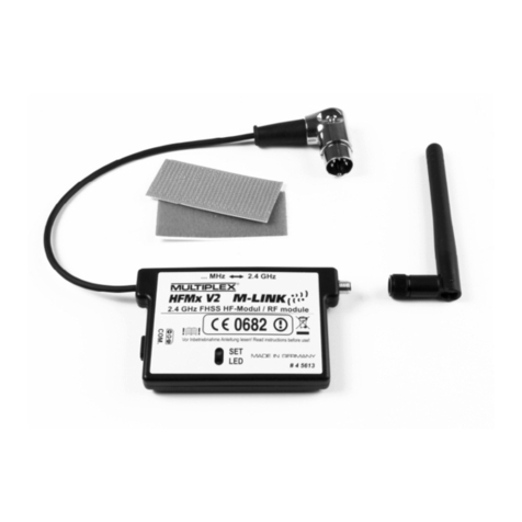
Multiplex HFM M-LINK Series User manual

MULTIPLEX Modellsport GmbH & Co.KG Westliche Gewerbestraße 1 D-75015 Bretten
© MULTIPLEX 2009, Printed in Germany
www.multiplex-rc.de
Bedienungsanleitung
3 -
8
Operating Instructions 9 - 14
Notice d´utilisation
15 - 20
Istruzioni per l´uso 21
-
26
Manual de Instrucciones 27
-
32
HFM
x
M
-
LINK
# 985 5341 (09-10-29-MIWA) D Esser


Bedienungsanleitung
2,4 GHz HF-Modul HFMx M-LINK
MULTIPLEX Modellsport GmbH & Co.KG • Westliche Gewerbestraße 1 • D-75015 Bretten (Gölshausen) • www.multiplex-rc.de Seite 1/6
Bedienungsa
nleitung 2,4 GHz HF-Modul HFMx M-LINK # 985 5341 (13-09-26/MIWA) • Irrtum und Änderung vorbehalten! •
MULTIPLEX
!Diese Bedienungsanleitung ist Bestandteil des
Produktes Sie beinhaltet wichtige Informationen
und Sicherheitshinweise Sie ist deshalb jederzeit
griffbereit aufzubewahren und beim Verkauf des
Produktes an Dritte weiterzugeben
1 TECHNISCHE DATEN
2,4 GHz HF-Modul HFMx M-LINK
Best.-Nr. # 4 5612
Frequenzbereich 2,4000 GHz … 2,4835 GHz
Eingeschränkter Frequenzbereich:
2,4000 GHz … 2,4540 GHz
Übertragungsart 2,4 GHz FHSS M-LINK System
Frequency Hopping Spread Spectrum
MULTIPLEX-LINK
Sendeleistung 100 mW EIRP
Stromaufnahme ca. 50 mA
Temperaturbereich
- 15°C … + 55°C
Abmessungen
(L x B x H) ca. 83 x 52 x 11 mm
(Gehäuse)
Gewicht ca. 65 g
2 SICHERHEITSHINWEISE
!Vor Inbetriebnahme Anleitung lesen.
!Nur für den vorgesehenen Einsatzbereich verwenden
(
3.).
!Keine technischen Veränderungen am HF-Modul vor-
nehmen.
Wenn Bauteile beschädigt sind, das HF-Modul bei einer
MULTIPLEX Servicestelle überprüfen lassen.
3 EINSATZBEREICH / KOMPATIBILITÄT
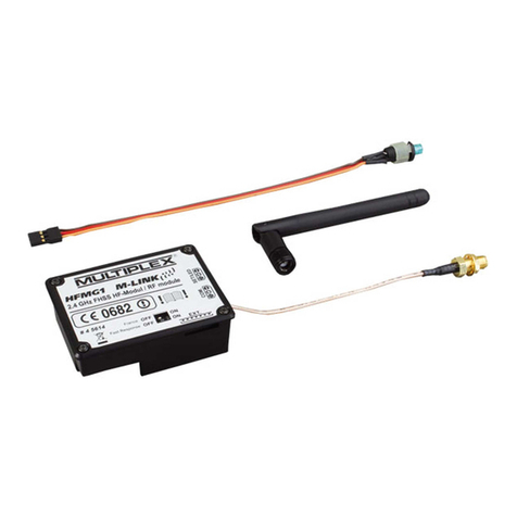
Das externe 2,4 GHz HF-Modul HFMx M-LINK ist ideal, wenn
Sie mit dem gleichen MULTIPLEX Sender häufig zwischen dem
35, 40, … MHz-Band und dem 2,4 GHz-Band wechseln, oder
einen älteren MULTIPLEX-Sender auch im 2,4 GHz-Band ein-
setzen möchten.
Das 2,4 GHz HF-Modul wird an die Lehrer / Schüler-Buchse des
Senders angesteckt und entweder direkt am Sender befestigt
oder am bzw. im Senderpult montiert. Es sind keinerlei Ände-
rungen am Sender notwendig.
Der nachfolgend verwendete Begriff „Lehrer / Schüler-Buchse“ steht für
die MULTIPLEX-Multifunktionsbuchse am Sender. Andere Begriffe hier-
für sind: DIN-Buchse, Ladebuchse, PC-Schnittstellen- bzw. Diagnose-
buchse.
Die Pluspunkte:
•Einfache und schnelle Umschaltung zwischen 35, 40, …
MHz (interner Sender) und 2,4 GHz M-LINK direkt am
2,4 GHz HF-Modul HFMx M-LINK über einen Schalter.
•Umschaltbar zwischen vollem Frequenzbereich und einge-
schränktem Frequenzbereich („Frankreich“-Mode“
4.).
•Umschaltbar zwischen 14 ms Servotaktzeit (Fast Response)
und 21 ms Servotaktzeit (
12.).
•Aktivierung von Binding-Modus (
8.) und Reichweitentest-
Modus (
11.) über die SET-Taste.
•LED-Statusanzeige.
Das 2,4 GHz HF-Modul HFMx M-LINK ist ausschließlich für den
Betrieb in folgenden MULTIPLEX-Sendern zugelassen:
•COCKPIT MM
•COCKPIT SX
•Combi 80 / sport / plus
•Combi 90
•Cockpit
•Commander
•Commander mc 2010 / 2015 / 2020
•EUROPA SPRINT
•EUROPA SPORT
•EUROPA mc 1005 / 1010 / 1020
•PiCOline
•PROFI mc 3010 / 3030 / 4000
•ROYAL mc
•ROYALevo 7, 9, 12
•ROYALpro 7, 9, 12
4 LANDESSPEZIFISCHE EINSCHRÄNKUNGEN
! Rechtlicher Hinweis: Sendegeräte dürfen nur auf den
Frequenzen /Sendekanälen eingestellt und betrieben wer-
den, die im jeweiligen Land zugelassen sind.
! Wichtig: Betrieb in bestimmten Ländern nur mit einge-
schränktem Frequenzbereich erlaubt!
In bestimmten Ländern ist der Betrieb von 2,4 GHz R/C-Sys-
temen mit 100 mW EIRP Ausgangsleistung nur in einem ein-
geschränkten Frequenzbereich erlaubt. Aus diesem Grund kann
das 2,4 GHz HF-Modul HFMx M-LINK wahlweise auch in einem
eingeschränkten Frequenzbereich betrieben werden (
13.).
Eine Übersicht über die betreffenden Länder finden Sie im Bei-
blatt „Betrieb des 2,4 GHz M-LINK Systems mit eingeschränk-
tem Frequenzbereich“.
5 DAS M-LINK ÜBERTRAGUNGSSYSTEM
M-LINK ist ein Übertragungssystem von MULTIPLEX. Es arbei-
tet auf dem 2,4 GHz ISM-Band und basiert auf einer modernen
FHSS Technologie (FHSS = Frequency Hopping Spread Spec-
trum).
Automatisches HF-Kanal-Management:
Eine manuelle HF-Kanalwahl (Wechselquarz, Synthesizer)
durch den Benutzer ist nicht mehr erforderlich. 2,4 GHz Spread
Spectrum Systeme teilen sich das Frequenzspektrum automa-
tisch. Es ist daher auch keine herkömmliche Frequenzüberwa-
chung nötig. Störungen durch Frequenzdoppelbelegungen (wie
im 35, 40, … MHz-Band möglich) sind praktisch ausgeschlos-
sen. Bei der ersten Inbetriebnahme des Systems müssen Sie
lediglich den Empfänger über eine einfache Binding-Prozedur
auf den Sender einlernen (Binding). Ab diesem Zeitpunkt verar-
beitet der Empfänger nur noch Signale Ihres eigenen Senders.
FHSS Technologie:
Im Abstand von wenigen Millisekunden springen Sender und
Empfänger im gleichen Rhythmus von Kanal zu Kanal. Während
eines Bruchteils dieser Zeit werden die Daten übertragen. Durch
die daraus resultierende kurze Kanal-Belegungszeit werden
Signalkonflikte minimiert und Störungen unterdrückt. Selbst
wenn Datenpakete auf einzelnen Kanälen verloren gehen, sind
durch das ständige, schnelle Springen auf den nächsten Kanal
Unterbrechungen für den Piloten nicht spürbar.

Bedienungsanleitung
2,4 GHz HF-Modul HFMx M-LINK
MULTIPLEX Modellsport GmbH & Co.KG • Westliche Gewerbestraße 1 • D-75015 Bretten (Gölshausen) • www.multiplex-rc.de Seite 2/6
Bedienungsa
nleitung 2,4 GHz HF-Modul HFMx M-LINK # 985 5341 (13-09-26/MIWA) • Irrtum und Änderung vorbehalten! •
MULTIPLEX
Hohe Daten- /Übertragungssicherheit:
Die bei 2,4 GHz zur Verfügung stehende enorme Bandbreite
ermöglicht das Übertragen von wesentlich höheren Datenmen-
gen,
als
dies
beispielsweise
bei
35 MHz
der
Fall
ist. Die
digitale
Modulation in Verbindung mit einer aufwändigen Fehlerprüfung
im Empfänger sichert eine ausgezeichnete Datenqualität.
Hohe Störfestigkeit:
Typische Störquellen im Modell wie z.B. Elektromotoren, elektro-
nische Geräte wie Steller / Regler, Zündungen von Verbren-
nungsmotoren usw. haben ein Störspektrum, dessen Maximum
deutlich unter dem 2,4 GHz-Bereich liegt. 2,4 GHz-Systeme las-
sen sich dadurch praktisch nicht stören, was in einem weiteren
Sicherheitsplus resultiert.
Schnelle, präzise Übertragung:
MULTIPLEX M-LINK ist ein digitales Übertragungssystem mit
bis zu 16 Servokanälen bei einer Auflösung von 12 bit (3872
Schritte). Der Rauschanteil bleibt bis zur Reichweitengrenze ohne
Einfluss auf die Stellpräzision der Servosignale. Auflösung,
Rückstellgenauigkeit und damit Steuerpräzision sind bis zur
Reichweitengrenze auf konstant hohem Niveau. Aufgrund der
digitalen Codierung arbeiten bei M-LINK sowohl HOLD als auch
FAIL-SAFE sehr präzise. Die Servotaktzeit ist von 21 ms (16-
Kanal-Betrieb) auf 14 ms im 12-Kanal-Betrieb (Fast Response)
umstellbar.
Kurze Senderantenne:
Die kurze 2,4 GHz Senderantenne ist robust und handlich. Auch
das Sichtfeld des Piloten wird nicht gestört.
6 MONTAGE DES
2,4 GHZ HF-MODULS HFMX M-LINK
6.1.: Festlegung des optimalen Montageorts für das
2,4 GHz HF-Modul HFMx M-LINK
Das HF-Modul wird bei Handsenderbetrieb direkt am Sender-
gehäuse befestigt. Ist der Sender in ein Senderpult einge-
schoben, können Sie das 2,4 GHz HF-Modul HFMx M-LINK
auch am bzw. im Senderpult montieren.
Bei der Festlegung des Montageorts beachten:
•Das HF-Modul so anbringen, dass die 2,4 GHz Antenne
möglichst weit vorne platziert ist (in Richtung Stirnseite des
Senders). Die 2,4 GHz Antenne darf nicht durch den Sender
verdeckt werden, eine „freie Sicht“ der Antenne zum Modell
ist sicherzustellen.
•Die Antenne des 2,4 GHz HF-Moduls HFMx M-LINK muss
sich am gewählten Montageort zur Realisierung der optima-
len Abstrahlcharakteristik drehen und schwenken lassen
(
10.).
•Der vorgesehene Montageort des HF-Moduls muss den An-
schluss des DIN-Steckers an die Lehrer / Schüler-Buchse
des Senders gestatten (Kabellänge beachten!).
•Achten Sie darauf, dass die Komponenten des HF-Moduls
(Gehäuse, Antenne, Kabel und Stecker) weder den Zugang
zu den Schaltern, Schiebern und Drehreglern, noch die Ab-
lesbarkeit des Sender-Displays einschränken.
•Beim Anbringen auf der Sender-Unterseite das HF-Modul
möglichst im Schutzbereich eines Haltebügels anbringen,
um eine mechanische Belastung für das HF-Modul beim
Ablegen des Senders auszuschließen.
6.2.: Befestigung des 2,4 GHz HF-Moduls HFMx M-LINK
Die Montage des 2,4 GHz HF-Moduls HFMx M-LINK wird nach-
folgend exemplarisch am Sendergehäuse einer PROFImc 4000
(Handsenderbetrieb) dargestellt. Soll das HF-Modul am bzw. im
Senderpult oder an einem anderen Sendertyp angebracht wer-
den, erfolgt die Montage sinngemäß.
1. Klettband (Veloursband) auf der Rückseite des HF-Moduls
im Bereich der Gehäusevertiefung aufkleben:
2. Klettband (Hakenseite) an der vorgesehenen Montagestelle
am Sendergehäuse aufkleben:
3. Das 2,4 GHz HF-Modul HFMx M-LINK am Sendergehäuse
befestigen:

Bedienungsanleitung
2,4 GHz HF-Modul HFMx M-LINK
MULTIPLEX Modellsport GmbH & Co.KG • Westliche Gewerbestraße 1 • D-75015 Bretten (Gölshausen) • www.multiplex-rc.de Seite 3/6
Bedienungsa
nleitung 2,4 GHz HF-Modul HFMx M-LINK # 985 5341 (13-09-26/MIWA) • Irrtum und Änderung vorbehalten! •
MULTIPLEX
6.3.: Anschluss des 2,4 GHz HF-Moduls HFMx M-LINK an
die Lehrer / Schüler-Buchse des Senders
1. DIN-Stecker mit der Lehrer / Schüler-Buchse am Sender ver-
binden. Für eine korrekte Platzierung die Nase im Stecker
beachten:
2. Bei ungünstigem Kabelaustritt am Stecker kann das Innenteil
des DIN-Steckers (Kontakte samt Fassung) gedreht werden:
•Schraube auf dem DIN-Stecker aufschrauben (Schlitz-
schraubendreher oder Torx) und Oberseite des DIN-
Steckers abnehmen.
•Innenteil (Kontakte samt Fassung) etwas anheben und
durch Drehen in die gewünschte Position bringen.
Achtung auf Kabel und Lötstellen!
•Oberseite des DIN-Steckers wieder aufsetzen, Schraube
festziehen, DIN-Stecker anstecken:
6.4.: 2,4 GHz Antenne montieren
2,4 GHz Antenne aufschrauben:
•Antenne dabei an der Rändelung fassen.
•Die Schraubverbindung muss fest sein, damit sich die
Antenne im Betrieb - z.B. beim Drehen im eingebauten
Zustand - keinesfalls lösen kann.
•Verschraubung in regelmäßigen Abständen überprüfen!
!Hinweis: Übermäßiger Krafteinsatz und Verkanten der Ein-
zelteile beim Verschrauben sind zu vermeiden!
7 FÜR DEN 2,4 GHZ BETRIEB:
IMMER BETRIEBSART PPM AUSWÄHLEN
(NICHT PCM)
Zum Betrieb mit dem M-LINK 2,4 GHz System muss am Sender
immer die Betriebsart PPM ausgewählt werden (nicht PCM!).
Dies gilt nicht nur für den Normalbetrieb (
9.), sondern auch
für die Modi Binding (
8.) und Reichweitentest (
11.).
8 BINDING-VORGANG
Sender mit M-LINK Technologie (hier mit dem 2,4 GHz HF-
Modul HFMx M-LINK) und Empfänger müssen zum Betrieb ein-
malig aufeinander „eingelernt“ werden. Dieser Vorgang wird als
„Binding“ bezeichnet.
!Hinweis:
Generelle Informationen zum Thema Binding sowie zu Fehler-
suche und Fehlerbehebung im Rahmen des Binding-Vorgangs
finden Sie in der Anleitung Ihres MULTIPLEX M-LINK Empfän-
gers.
Ablauf des Binding-Vorgangs:
1. Sender AUS schalten.
2. Sender und Empfänger in unmittelbare Nähe zueinander
bringen.
3. Sender mit M-LINK Technologie im Binding-Modus EIN
schalten, dafür:
•Schiebeschalter an der Flachseite des 2,4 GHz HF-
Moduls HFMx M-LINK in Position „2.4 GHz“ bringen
(
9.).
•SET-Taste am 2,4 GHz HF-Modul HFMx M-LINK
drücken und gedrückt halten.
•Sender EIN schalten.
•SET-Taste loslassen, sobald die LED am 2,4 GHz
HF-Modul HFMx M-LINK schnell blinkt.
4. M-LINK Empfänger im Binding-Modus EIN schalten
(mit gedrückter SET-Taste EIN schalten, siehe Anleitung des
M-LINK Empfängers):
=> Die Bindingprozedur läuft.
5. Nachdem sich Sender und Empfänger gefunden haben
(wenige Sekunden), gehen beide automatisch in den
regulären Sende- und Empfangsbetrieb über
(Betrieb
9.):
=> Die LED am 2,4 GHz HF-Modul blinkt langsam und
regelmäßig ca. alle 2 Sekunden.

Bedienungsanleitung
2,4 GHz HF-Modul HFMx M-LINK
MULTIPLEX Modellsport GmbH & Co.KG • Westliche Gewerbestraße 1 • D-75015 Bretten (Gölshausen) • www.multiplex-rc.de Seite 4/6
Bedienungsa
nleitung 2,4 GHz HF-Modul HFMx M-LINK # 985 5341 (13-09-26/MIWA) • Irrtum und Änderung vorbehalten! •
MULTIPLEX
9 BETRIEB
Das 35, 40, … MHz HF-Modul verbleibt auch während des
Betriebs mit 2,4 GHz im Sender und wird nicht ausgebaut. Mit
dem an der Flachseite des 2,4 GHz HF-Moduls angebrachten
Schalter können Sie zwischen den verschiedenen Frequenz-
bändern (d.h. zwischen dem intern eingebauten 35 oder 40, …
MHz HF-Teil oder dem externen 2,4 GHz HF-Modul HFMx
M-LINK) hin und her wechseln:
•Schalterstellung „… MHz“: 35, 40, … MHz Betrieb
•Schalterstellung „2.4 GHz“: 2,4 GHz M-LINK Betrieb
Reihenfolge beim EIN und AUS schalten der R/C-Anlage:
Behalten Sie die gewohnte Reihenfolge beim EIN und AUS
schalten auch beim Betrieb mit 2,4 GHz bei:
•Zuerst Sender EIN schalten,
dann Empfänger EIN schalten.
•Zuerst Empfänger AUS schalten,
dann Sender AUS schalten.
Für den Betrieb auf 2,4 GHz M-LINK gehen Sie wie folgt vor:
•Sender AUS schalten.
•35, 40, … MHz Senderantenne abnehmen
(Teleskopantenne oder Kurzantenne).
•Schiebeschalter am 2,4 GHz HF-Modul HFMx M-LINK in
Stellung „2.4 GHz“ bringen.
•Sender EIN schalten.
Die 2,4 GHz M-LINK-Übertragung ist aktiv, wenn die LED am
2,4 GHz HF-Modul HFMx M-LINK langsam und regelmäßig
ca. alle 2 Sekunden blinkt.
•M-LINK Empfänger EIN schalten.
Das M-LINK System ist betriebsbereit.
!Hinweis:
Während des Betriebs auf 2,4 GHz wird das 35, 40, … MHz
HF-Modul automatisch abgeschaltet.
Für den Betrieb auf 35, 40, … MHz gehen Sie wie folgt vor:
•Sender AUS schalten.
•35, 40, … MHz Senderantenne montieren
(Teleskopantenne oder Kurzantenne).
•Schiebeschalter am 2,4 GHz HF-Modul HFMx M-LINK in
Stellung „… MHz“ bringen.
•Sender EIN schalten.
Der Sender sendet auf dem 35, 40, … MHz Frequenzband.
Die LED am 2,4 GHz HF-Modul HFMx M-LINK bleibt AUS.
•35, 40, … MHz Empfänger EIN schalten.
Das 35, 40, … MHz System ist betriebsbereit.
!Hinweis:
Während des Betriebs auf 35, 40, … MHz ist das 2,4 GHz HF-
Modul HFMx M-LINK abgeschaltet.
Der DIN-Stecker bleibt während des 35, 40, … MHz-Betriebs an
der Lehrer / Schüler-Buchse des Senders angesteckt. Er wird le-
diglich dann abgezogen, wenn die Lehrer / Schüler Buchse für
andere Zwecke benötigt wird (Laden des Senderakkus, Betrieb
an einem Flugsimulator, Diagnosetätigkeiten, …).
!Achtung:
•Vor dem Start durch einen Rudercheck sicherstellen,
dass der Sender auf dem korrekten Frequenzband
sendet!
•Niemals während des Flug- oder Fahrbetriebs das
Frequenzband wechseln!
10 IDEALSTELLUNG DER SENDERANTENNE
WÄHREND DES SENDEBETRIEBS
Die 2,4 GHz Senderantenne ist im eingebauten Zustand seitlich
drehbar und nach oben schwenkbar.
Für den Sendebetrieb knicken Sie die Senderantenne am
Schwenkgelenk in etwa rechtwinklig ab und neigen die Sender-
antenne anschließend waagerecht nach links oder rechts zur
Seite (siehe Abbildung):
Bei Anwendungen, bei denen das Modell nicht direkt über dem
Sender oder nicht direkt unter dem Sender betrieben wird (ins-
besondere bei Autos und Schiffen), ist eine Antennenstellung
senkrecht nach oben optimal.
!Wichtig:
Zielen Sie niemals mit der Antenne auf das Modell. In Ver-
längerung der Antenne ist die Abstrahlung physikalisch bedingt
am geringsten.
!Hinweis:
Vor dem Betrieb mit 2,4 GHz M-LINK ist die 35, 40, … MHz
Senderantenne (Teleskopantenne oder Kurzantenne) abzuneh-
men!

Bedienungsanleitung
2,4 GHz HF-Modul HFMx M-LINK
MULTIPLEX Modellsport GmbH & Co.KG • Westliche Gewerbestraße 1 • D-75015 Bretten (Gölshausen) • www.multiplex-rc.de Seite 5/6
Bedienungsa
nleitung 2,4 GHz HF-Modul HFMx M-LINK # 985 5341 (13-09-26/MIWA) • Irrtum und Änderung vorbehalten! •
MULTIPLEX
11 REICHWEITENTEST
Die Durchführung von regelmäßigen Reichweitentests ist - auch
bei Verwendung eines 2,4 GHz Systems - sehr wichtig, um eine
sichere Funktion der Fernsteueranlage zu gewährleisten und um
Störungsursachen rechtzeitig zu erkennen. Insbesondere:
•Vor Einsatz neuer oder veränderter Komponenten bzw. deren
neuen oder veränderten Anordnung.
•Vor dem Einsatz von Fernsteuerkomponenten, die zuvor an
einem Absturz / Crash oder einer „harten“ Landung beteiligt
waren.
•Wenn zuvor Unregelmäßigkeiten beim Betrieb festgestellt
wurden.
Wichtig:
•Reichweitentest immer mit Hilfe einer zweiten Person durch-
führen, die das Modell sichert und beobachtet.
•Führen Sie den Reichweitentest nur durch, wenn keine an-
deren Sender in Betrieb sind.
Vorbereitung und Durchführung des Reichweitentests:
1. Sender AUS schalten und 35, 40, … MHz Senderantenne
abnehmen. Darauf achten, dass der Schiebeschalter des
2,4 GHz HF-Moduls HFMx M-LINK in Position „2.4 GHz“
steht (
9.).
2. Sender EIN schalten und SET-Taste am 2,4 GHz HF-Modul
innerhalb von 4 Sekunden nach dem EIN schalten des Sen-
ders so lange drücken, bis die LED am 2,4 GHz HF-Modul
HFMx M-LINK Dauerleuchten zeigt.
3. M-LINK Empfänger EIN schalten und Reichweitentest wie in
den Bedienungsanleitungen zu den M-LINK Empfängern
beschrieben durchführen.
!Achtung: In der Betriebsart „Reichweitentest“ ist
die Sendeleistung reduziert! Niemals das Modell mit
reduzierter Sendeleistung im Reichweitentest-Modus
starten!
4. Nach dem Reichweitentest den Sender mit M-LINK Tech-
nologie AUS und anschließend wieder EIN schalten, um
in den normalen Sendebetrieb mit voller Reichweite zu
wechseln!
12 FAST RESPONSE EIN / AUS
Im Fast Response Modus, der mit einer Taktzeit von 14 ms be-
sonders schnell ist, stehen bis zu 12 Servokanäle zur Verfügung.
Diese verkürzte Taktzeit kann bei analogen Servos zu unruhi-
gem Lauf oder zum Oszillieren führen.
Für diesen Fall kann am 2,4 GHz HF-Modul HFMx M-LINK der
Fast Response Modus AUS geschaltet werden. Die Taktzeit
beträgt dann 21 ms.
Zum EIN oder AUS schalten von Fast Response gehen Sie
wie folgt vor:
1. Sender AUS schalten.
2. Betriebsart mit dem linken der beiden Schalter (Schalter 1)
auf der Unterseite des 2,4 GHz HF-Moduls HFMx M-LINK
umstellen:
•Schalter 1 in Stellung ON (oben) = Fast Response EIN
•Schalter 1 in Stellung unten (AUS) = Fast Response AUS
Werkseinstellung: Fast Response Modus AUS.
!Hinweis: Zum Umstellen des Schalters einen kleinen
Schraubendreher (niemals einen Bleistift) verwenden!
3. 2,4 GHz HF-Modul HFMx M-LINK wieder am Sender
anbringen.
!Hinweis:
Nach einer (De-)Aktivierung des Fast Response Modus
muss erneut ein Binding durchgeführt werden (
8.)!
13 BETRIEB DES 2,4 GHZ HF-MODULS
HFMX M-LINK MIT EINGESCHRÄNKTEM
FREQUENZBEREICH
Vor dem Einsatz des M-LINK Systems in bestimmten Ländern
muss der dort zulässige – reduzierte - Frequenzbereich (
4.)
aktiviert werden. Eine Übersicht über die betreffenden Länder
finden Sie im Beiblatt „Betrieb des 2,4 GHz M-LINK Systems mit
eingeschränktem Frequenzbereich“.
Zur Aktivierung des eingeschränkten Frequenzbereichs ge-
hen Sie wie folgt vor:
1. Sender AUS schalten.
2. Den rechten der beiden auf der Unterseite des 2,4 GHz HF-
Moduls HFMx M-LINK angebrachten Schalter (Schalter 2)
mit einem kleinen Schraubendreher in Stellung ON (oben)
bringen. Achtung: verwenden Sie für diesen Arbeitsschritt
niemals einen Bleistift!
3. Danach mit allen zu verwendeten Empfängern ein Binding
durchführen (
8.).
!Hinweis:
Soll das M-LINK System wieder auf dem maximal möglichen
Frequenzbereich betrieben werden:
1. Den rechten Schalter (Schalter 2) wieder in Stellung AUS
(nach unten) bringen (Werkseinstellung).
2. Danach mit allen zu verwendenden Empfängern ein Bin-
ding durchführen (
8.).

Bedienungsanleitung
2,4 GHz HF-Modul HFMx M-LINK
MULTIPLEX Modellsport GmbH & Co.KG • Westliche Gewerbestraße 1 • D-75015 Bretten (Gölshausen) • www.multiplex-rc.de Seite 6/6
Bedienungsa
nleitung 2,4 GHz HF-Modul HFMx M-LINK # 985 5341 (13-09-26/MIWA) • Irrtum und Änderung vorbehalten! •
MULTIPLEX
14 CE-KONFORMITÄTSERKLÄRUNG
Die Bewertung des Gerätes erfolgte nach europäisch
harmonisierten Richtlinien.
Sie besitzen daher ein Produkt, das hinsichtlich der Konstruktion
die Schutzziele der Europäischen Gemeinschaft zum sicheren
Betrieb der Geräte erfüllt.
Die ausführliche CE-Konformitätserklärung finden Sie als PDF-
Datei im Internet bei www.multiplex-rc.de im Bereich DOWN-
LOADS unter PRODUKT-INFOS.
15 ENTSORGUNGSHINWEISE
Elektrogeräte, die mit der durchgestrichenen Mülltonne
gekennzeichnet sind, zur Entsorgung nicht in den Haus-
müll geben, sondern einem geeigneten Entsorgungs-
system zuführen.
In Ländern der EU (Europäische Union) dürfen Elektro-
geräte nicht durch den Haus- bzw. Restmüll entsorgt
werden (WEEE - Waste of Electrical and Electronic Equipment,
Richtlinie 2002/ 96/EG). Sie können Ihr Altgerät bei öffentlichen
Sammelstellen Ihrer Gemeinde bzw. ihres Wohnortes (z.B. Re-
cyclinghöfe) abgeben. Das Gerät wird dort für Sie fachgerecht
und kostenlos entsorgt.
Mit der Rückgabe Ihres Altgerätes leisten Sie einen wichtigen
Beitrag zum Schutz der Umwelt!
16 GEWÄHRLEISTUNG /
HAFTUNGSAUSSCHLUSS
Die Firma MULTIPLEX Modellsport GmbH & Co.KG übernimmt
keinerlei Haftung für Verluste, Schäden oder Kosten, die sich
aus fehlerhafter Verwendung und Betrieb ergeben oder in
irgendeiner Weise damit zusammenhängen. Soweit gesetzlich
zulässig, ist die Verpflichtung der Firma MULTIPLEX Modell-
sport GmbH & Co.KG zur Leistung von Schadenersatz, gleich
aus welchem Rechtsgrund, begrenzt auf den Rechnungswert
der an dem schadenstiftenden Ereignis unmittelbar beteiligten
Warenmenge der Firma MULTIPLEX Modellsport GmbH & Co.KG.
Dies gilt nicht, soweit die MULTIPLEX Modellsport GmbH &
Co.KG nach zwingenden gesetzlichen Vorschriften wegen Vor-
satzes oder grober Fahrlässigkeit unbeschränkt haftet.
Für unsere Produkte leisten wir entsprechend den derzeit
geltenden gesetzlichen Bestimmungen Gewähr. Wenden Sie
sich mit Gewährleistungsfällen an den Fachhändler, bei dem Sie
das Produkt erworben haben.
Von der Gewährleistung ausgeschlossen sind Fehlfunktionen,
die verursacht wurden durch:
•Unsachgemäßen Betrieb
•Falsche, nicht oder verspätet, oder nicht von einer autori-
sierten Stelle durchgeführte Wartung
•Falsche Anschlüsse
•Verwendung von nicht originalem MULTIPLEX-Zubehör
•Veränderungen / Reparaturen, die nicht von MULTIPLEX
oder einer MULTIPLEX-Servicestelle ausgeführt wurden
•Versehentliche oder absichtliche Beschädigungen
•Defekte, die sich aus der normalen Abnutzung ergeben
•Betrieb außerhalb der technischen Spezifikationen oder
im Zusammenhang mit Komponenten anderer Hersteller.

Operating Instructions
HFMx M-LINK 2.4 GHz RF Module
MULTIPLEX Modellsport GmbH & Co.KG • Westliche Gewerbestraße 1 • D-75015 Bretten (Gölshausen) • www.multiplex-rc.de Page 1/6
Instructions HFM
x M-LINK 2.4 GHz RF module # 985 5341 (013-09-26/MIWA) • Errors and omissions excepted! •
MULTIPLEX
!hese operating instructions form an integral
part of the product, and contain important infor-
mation and safety notes. Please store them in a
safe place, where you can find them at any time,
and pass them on to the new owner if you ever
dispose of the product.
1. SPECIFICA ION
HFMx M-LINK 2.4 GHz RF module
Order No. # 4 5612
Frequency range 2.4000 GHz … 2.4835 GHz
Restricted frequency range:
2.4000 GHz … 2.4540 GHz
Transmission type 2.4 GHz FHSS M-LINK system
Frequency Hopping Spread Spectrum
MULTIPLEX-LINK
Output power 100 mW EIRP
Current drain approx. 50 mA
Temperature range
- 15°C … + 55°C
Dimensions
(L x W x H) approx. 83 x 52 x 11 mm
(case)
Weight approx. 65 g
2. SAFE Y NO ES
!Please read the instructions before using the product.
!Use the unit only for the intended applications (
3.).
!Do not make any modifications of a technical nature to
the RF module.
If any part is damaged, send the RF module to a
MULTIPLEX Service Centre for checking.
3. APPLICA ION / COMPA IBILI Y
The external HFMx M-LINK 2.4 GHz RF module is the ideal
solution if you wish to use the same MULTIPLEX transmitter and
switch frequently between the 35, 40, … MHz band and the 2.4
GHz band; or alternatively if you just wish to use an older MUL-
TIPLEX transmitter on the 2.4 GHz band.
The 2.4 GHz RF module is connected to the transmitter’s Trai-
ner socket, and can either be attached directly to the transmitter
or mounted in the transmitter tray. No modifications to the trans-
mitter of any kind are necessary.
The term “Trainer socket” used in these instructions refers to the MULTI-
PLEX multi-function socket fitted to the transmitter. Other names used
for it are: DIN socket, charge socket, PC port and Diagnosis socket.
The advantages:
•Simple, rapid method of switching between 35, 40, … MHz
(internal transmitter) and 2.4 GHz M-LINK, carried out
directly on the HFMx M-LINK 2.4 GHz RF module using
a switch.
•Can be switched between full frequency range and limited
frequency range (“France” mode
4.).
•Can be switched between 14 ms servo frame rate (Fast
Response) and 21 ms servo frame rate (
12.).
•Integral SET button for activating Binding mode (
8.) and
range-check mode (
11.).
•LED status indicator.
The HFMx M-LINK 2.4 GHz RF module is approved exclusively
for use with the following MULTIPLEX transmitters:
•COCKPIT MM
•COCKPIT SX
•Combi 80 / sport / plus
•Combi 90
•Cockpit
•Commander
•Commander mc 2010 / 2015 / 2020
•EUROPA SPRINT
•EUROPA SPORT
•EUROPA mc 1005 / 1010 / 1020
•PiCOline
•PROFI mc 3010 / 3030 / 4000
•ROYAL mc
•ROYALevo 7, 9, 12
•ROYALpro 7, 9, 12
4. COUN RY-SPECIFIC RES RIC IONS
! Legal note: transmitting apparatus must only be set up
and operated on frequencies /transmission channels which
are approved for the country in which it is to be used.
! Important: in particular countries the module may only
be used within a restricted frequency range.
In certain countries the operation of 2.4 GHz RC systems with
an output power of 100 mW EIRP is only permitted within a
restricted frequency range. For this reason the HFMx M-LINK
2.4 GHz RF module offers the option of limiting the frequency
range (
13.).
You can find an overview of the countries affected by this
restriction in the separate sheet entitled “Operating the 2.4 GHz
M-LINK System with Restricted Frequency Range”.
5. HE M-LINK RANSMISSION SYS EM
M-LINK is a transmission system designed by MULTIPLEX. It
operates on the 2.4 GHz ISM band, and exploits modern FHSS
technology (FHSS = Frequency Hopping Spread Spectrum).
Automatic RF channel management:
With this system it is no longer necessary for the operator to
select the RF channel manually (plug-in crystals, Synthesizer).
2.4 GHz Spread Spectrum systems automatically divide up the
frequency spectrum, and this eliminates the need for conven-
tional frequency monitoring. Same-channel interference (as is
possible on the 35, 40 … MHz band) is virtually impossible. The
first time the system is used you just have to carry out a simple
binding procedure to link the transmitter to the receiver. From
this moment on the receiver only responds to the signals from
your specific transmitter.
FHSS technology:
The transmitter and receiver jump from channel to channel every
few milliseconds, maintaining the same rhythm; the data is
transmitted during a fraction of this period. The resultant brief
period of channel occupation minimises signal conflicts, and
suppresses interference. Even if data packets are lost on par-
ticular channels, the constant high-speed hopping to the next
channel makes any interruptions unnoticeable to the pilot.
Good data security / transmission security:
The enormous bandwidth available on 2.4 GHz makes it pos-
sible to transmit much greater quantities of data than is possible,
for example on the 35 MHz band. Digital modulation in con-
junction with sophisticated error-checking in the receiver guaran-
tee outstanding data quality.

Operating Instructions
HFMx M-LINK 2.4 GHz RF Module
MULTIPLEX Modellsport GmbH & Co.KG • Westliche Gewerbestraße 1 • D-75015 Bretten (Gölshausen) • www.multiplex-rc.de Page 2/6
Instructions HFM
x M-LINK 2.4 GHz RF module # 985 5341 (013-09-26/MIWA) • Errors and omissions excepted! •
MULTIPLEX
Good resistance to interference:
Typical interference sources in the model, such as electric
motors, and electronic devices such as speed controllers, petrol
engine ignition systems etc., have an interference spectrum
whose maximum frequency is significantly below the 2.4 GHz
range. It is virtually impossible for 2.4 GHz systems to suffer
interference from such sources, and this provides a further im-
provement in security.
Fast, accurate transmission:
MULTIPLEX M-LINK is a digital transmission system offering a
maximum of sixteen servo channels with a resolution of 12 bits
(3872 steps). Background noise has no effect on servo signal
accuracy right up to the limits of range. Resolution, centring
precision and with it general accuracy of control are at a con-
stant high level up to the effective limits of range. M-LINK’s
digital encoding allows both HOLD and FAIL-SAFE to operate
very accurately. The servo pulse rate of 21 ms (16-channel mode)
can be reduced to 14 ms (12-channel mode - Fast Response).
Short transmitter aerial:
The short 2.4 GHz transmitter aerial is robust and easy to handle,
and it does not impinge on the pilot’s field of vision.
6. INS ALLING HE
HFMX M-LINK 2.4 GHZ RF MODULE
6.1.: Determining the optimum location for the
HFMx M-LINK 2.4 GHz RF module
If you use a hand-held transmitter, the new RF module can be
attached directly to the transmitter case. If you prefer to use the
transmitter in a transmitter tray, the HFMx M-LINK 2.4 GHz RF
module can also be installed in or on the tray.
Please note the following when deciding on the location:
•The RF module should be mounted in such a way that the
2.4 GHz aerial is as far forward as possible (towards the top
face of the transmitter). The 2.4 GHz aerial must not be
concealed or obstructed by the transmitter, as it needs to
have a “free view” of the model.
•When the HFMx M-LINK 2.4 GHz RF module is installed, it
must be possible to rotate and tilt the aerial attached to the
module to ensure that the radiation pattern is as good as
possible (
10.).
•It must be possible to connect the DIN plug attached to the
RF module to the transmitter’s Trainer socket when the mo-
dule is in place (check cable length!).
•Ensure that the components of the RF module (case, aerial,
lead and plug) do not obstruct access to the transmitter’s
switches, sliders and rotary controls, nor prevent the pilot
reading the transmitter screen.
•If you wish to attach the RF module to the back of the trans-
mitter, if at all possible position it in the area protected by a
transport handle, to avoid the risk of mechanical stress on
the module when the transmitter is put down.
6.2.: Securing the HFMx M-LINK 2.4 GHz RF module
Our example illustrates the method of fixing the HFMx M-LINK
2.4 GHz RF module to the case of a PROFImc 4000 transmitter
(used hand-held). The same basic method can be used to attach
the RF module to or in a transmitter tray, or to a different type of
transmitter.
1. Stick the Velcro tape (loop side) to the recessed areas on the
back of the RF module:
2. Stick the Velcro tape (hook side) to the transmitter case in
the appropriate position:
3. Attach the HFMx M-LINK 2.4 GHz RF module to the trans-
mitter case:

Operating Instructions
HFMx M-LINK 2.4 GHz RF Module
MULTIPLEX Modellsport GmbH & Co.KG • Westliche Gewerbestraße 1 • D-75015 Bretten (Gölshausen) • www.multiplex-rc.de Page 3/6
Instructions HFM
x M-LINK 2.4 GHz RF module # 985 5341 (013-09-26/MIWA) • Errors and omissions excepted! •
MULTIPLEX
6.3.: Connecting the HFMx M-LINK 2.4 GHz RF module to
the transmitter’s Trainer socket
1. Insert the DIN plug in the transmitter’s Trainer socket. The
correct orientation is dictated by the lug in the connector:
2. If the cable exits the connector in an awkward position, the
internal part of the DIN plug (contacts and contact holder)
can be rotated as follows:
•Undo the screw in the DIN plug (plain or Torx screw-
driver) and lift off the top of the connector housing.
•Raise the internal part (contacts and contact holder)
slightly, and rotate the assembly to the correct position.
Take care not to damage any wires or soldered joints!
•Replace the top housing of the DIN plug and tighten the
retaining screw. Insert the DIN plug in the socket:
6.4.: Installing the 2.4 GHz aerial
Screw the 2.4 GHz aerial into the socket on the module:
•Grip the aerial by the knurled section.
•The screwed joint must be firmly tightened, so that the aerial
cannot possibly come loose in use – e.g. when it is rotated in
the installed position.
•Check the screwed aerial joint at regular intervals!
!Note: avoid using excessive force, and keep the parts cor-
rectly aligned when screwing them together.
7. 2.4 GHZ OPERA ION:
ALWAYS SELEC PPM MODE (NO PCM)
To operate using the M-LINK 2.4 GHz system the transmitter
must always be set to PPM mode (not PCM!).
This applies not only to normal operations (
9.), but also to
binding mode (
8.) and range-check mode (
11.).
8. BINDING PROCEDURE
The transmitter with M-LINK technology (in this case with the
HFMx M-LINK 2.4 GHz RF module) and the receiver will not
work until they have been “taught” to recognise each other. This
process is known as “binding”.
!Note:
You will find general information on the subject of binding, and
on fault-finding and correction relating to the binding procedure,
in the operating instructions supplied with your MULTIPLEX
M-LINK receiver.
The binding procedure in detail:
1. Switch the transmitter OFF.
2. Place the transmitter and receiver very close to each other.
3. Switch the M-LINK transmitter ON in binding mode. This is
accomplished as follows:
•Move the slide switch on the flat face of the HFMx
M-LINK 2.4 GHz RF module to the “2.4 GHz” position
(
9.).
•Press the SET button on the HFMx M-LINK 2.4 GHz
RF module and hold it pressed in.
•Switch the transmitter ON.
•Release the SET button as soon as the LED on the
HFMx M-LINK 2.4 GHz RF module starts flashing
at a rapid rate.
4. Switch the M-LINK receiver ON in binding mode
(switch ON with the SET button pressed in; see the
instructions provided with the M-LINK receiver):
=> The binding process now takes place.
5. When the transmitter and receiver have identified each other
(this takes a few seconds), both automatically switch to
regular transmit / receive mode
(The system in use
9.):
=> The LED on the 2.4 GHz RF module flashes slowly and
regularly at intervals of approximately two seconds.

Operating Instructions
HFMx M-LINK 2.4 GHz RF Module
MULTIPLEX Modellsport GmbH & Co.KG • Westliche Gewerbestraße 1 • D-75015 Bretten (Gölshausen) • www.multiplex-rc.de Page 4/6
Instructions HFM
x M-LINK 2.4 GHz RF module # 985 5341 (013-09-26/MIWA) • Errors and omissions excepted! •
MULTIPLEX
9. HE SYS EM IN USE
The 35, 40, … MHz RF module does not need to be removed
from the transmitter, i.e. it remains in place even when the
system is operated on 2.4 GHz. The switch on the flat face of
the 2.4 GHz RF module can be used to switch to and fro
between the different frequency bands (i.e. between the in-
ternally fitted 35 or 40, … MHz RF section and the external
HFMx M-LINK 2.4 GHz RF module):
•Switch position “… MHz”: 35, 40, … MHz operation
•Switch position “2.4 GHz”: 2.4 GHz M-LINK operation
Sequence when switching the RC system ON and OFF:
Even when using the 2.4 GHz band you should keep to the usual
sequence when switching the system ON and OFF:
•First switch the transmitter ON,
then switch the receiver ON.
•First switch the receiver OFF,
the switch the transmitter OFF.
The procedure for using the 2.4 GHz M-LINK system:
•Switch the transmitter OFF.
•Unscrew the 35, 40, … MHz transmitter aerial
(telescopic or stub aerial).
•Move the slide switch on the HFMx M-LINK 2.4 GHz RF
module to the “2.4 GHz” position.
•Switch the transmitter ON.
2.4 GHz M-LINK transmission is active when the LED on the
HFMx M-LINK 2.4 GHz RF module flashes slowly and
regularly at two-second intervals.
•Switch the M-LINK receiver ON.
The M-LINK system is now ready for use.
!Note:
The 35, 40, … MHz RF module is automatically switched off
when the transmitter is operating on 2.4 GHz.
The procedure for using the system on 35, 40, … MHz:
•Switch the transmitter OFF.
•Install the 35, 40, … MHz transmitter aerial
(telescopic or stub aerial).
•Move the slide switch on the HFMx M-LINK 2.4 GHz
RF module to the “… MHz” position.
•Switch the transmitter ON.
The transmitter broadcasts on the 35, 40, … MHz band. The
LED on the HFMx M-LINK 2.4 GHz RF module stays OFF.
•Switch the 35, 40, … MHz receiver ON.
The 35, 40, … MHz system is now ready for use.
!Note:
The HFMx M-LINK 2.4 GHz RF module is switched off when
the transmitter is operating on 35, 40, … MHz.
When the transmitter is used on 35, 40 ... MHz, the DIN plug
remains connected to the transmitter’s Trainer socket. It only
needs to be disconnected if the Trainer socket is required for
some other purpose (charging the transmitter battery, use with a
flight simulator, Diagnosis activities, …).
!Caution:
•Before you fly a model, carry out a range check to
ensure that the transmitter is operating on the cor-
rect frequency band!
•Never change the frequency band when you are
operating a model!
10. IDEAL RANSMI ER AERIAL ORIEN A ION
WHEN USING HE RANSMI ER
When installed, the 2.4 GHz transmitter aerial can be rotated to
either side and swivelled upwards.
Before using the transmitter, the aerial should be angled
approximately at right-angles at the swivel joint, then swivelled
either to left or right in the horizontal plane (see illustration):
For applications where the model is not operated directly above
or below the transmitter, the optimum aerial orientation is verti-
cally upwards; this applies in particular to model cars and boats.
!Important:
Never point the aerial directly at the model. For physical reasons
the signal radiated from the aerial is at its weakest in an imagi-
nary line extending straight out from the aerial.
!Note:
Remove the 35, 40, … MHz transmitter aerial (telescopic or stub
aerial) before you operate the 2.4 GHz M-LINK system!

Operating Instructions
HFMx M-LINK 2.4 GHz RF Module
MULTIPLEX Modellsport GmbH & Co.KG • Westliche Gewerbestraße 1 • D-75015 Bretten (Gölshausen) • www.multiplex-rc.de Page 5/6
Instructions HFM
x M-LINK 2.4 GHz RF module # 985 5341 (013-09-26/MIWA) • Errors and omissions excepted! •
MULTIPLEX
11. RANGE CHECKING
Regular range checks are very important - even when using a
2.4 GHz system - in order to ensure reliable operation of the ra-
dio control system, and to give you a chance to detect sources
of interference in good time. This applies in particular:
•Before the use of new or changed components, or existing
components in a new or modified arrangement.
•Before re-using radio control system components which were
previously involved in a crash or a hard landing.
•If you have encountered problems on a previous flight.
Important:
•Always ask a second person to help you with your range
check, so that one of you can secure and observe the model.
•The range check should only be carried out if there are no
other transmitters switched on at the same time.
Preparing and carrying out a range check:
1. Switch the transmitter OFF and unscrew the 35, 40, … MHz
transmitter aerial. Ensure that the slide switch on the HFMx
M-LINK 2.4 GHz RF module is in the “2.4 GHz” position
(
9.).
2. Switch the transmitter ON, and press the SET button on the
2.4 GHz RF module within four seconds of switching ON.
Hold the button pressed in until the LED on the HFMx
M-LINK 2.4 GHz RF module lights up constantly.
3. Switch the M-LINK receiver ON, and carry out the range check
as described in the operating instructions supplied with your
M-LINK receiver.
!Caution: transmitter power is reduced in “range
check” mode! Never attempt to fly a model in range
check mode, i.e. with reduced transmitter power!
4. After the range check, switch the M-LINK transmitter
OFF and then ON again; this switches it back to normal
transmit mode with full range!
12. FAS RESPONSE ON / OFF
In Fast Response mode, which operates at the ultra-rapid pulse
rate of 14 ms, up to twelve servo channels are available. This
reduced pulse rate can cause analogue servos to oscillate or run
jerkily.
If this should occur, it is possible to switch Fast Response mode
OFF on the HFMx M-LINK 2.4 GHz RF module. The frame rate
is then 21 ms.
This is the procedure for switching Fast Response ON or
OFF:
1. Switch the transmitter OFF.
2. You will find two switches on the underside of the HFMx
M-LINK 2.4 GHz RF module. Move the left-hand switch
(switch 1) to change the mode of operation:
•Switch 1 in ON position (up) = Fast Response ON
•Switch 1 OFF position (down) = Fast Response OFF
Factory default setting: Fast Response mode OFF.
!Note: use a small screwdriver (never a pencil!) to operate
the switch!
3. Re-attach the HFMx M-LINK 2.4 GHz RF module to the
transmitter.
!Note:
If you activate or disable Fast Response mode, you must
carry out the binding procedure again (
8.)!
13. OPERA ING HE HFMX M-LINK 2.4 GHZ
RF MODULE WI H RES RIC ED FREQUENCY
RANGE
In particular countries the M-LINK system must not be used
without activating the reduced frequency range approved in that
region (
4.). For an overview of the countries concerned
please refer to the separate sheet entitled “Operating the 2.4
GHz M-LINK system with restricted frequency range”.
This is the procedure for activating the restricted frequency
range:
1. Switch the transmitter OFF.
2. You will find two switches on the underside of the HFMx
M-LINK 2.4 GHz RF module. Move the right-hand switch
(switch 2) to the ON (up) position using a small screwdriver.
Caution: never use a pencil to do this!
3. Now repeat the binding procedure with all the receivers you
wish to use with the transmitter (
7.).
!Note:
If you subsequently decide to operate the M-LINK system
using the maximum possible frequency range:
1. Move the right-hand switch (switch 2) back to the OFF
position (down / default setting).
2. Now repeat the binding procedure with all the receivers
you wish to use with the transmitter (
7.).

Operating Instructions
HFMx M-LINK 2.4 GHz RF Module
MULTIPLEX Modellsport GmbH & Co.KG • Westliche Gewerbestraße 1 • D-75015 Bretten (Gölshausen) • www.multiplex-rc.de Page 6/6
Instructions HFM
x M-LINK 2.4 GHz RF module # 985 5341 (013-09-26/MIWA) • Errors and omissions excepted! •
MULTIPLEX
14. CE CONFORMI Y DECLARA ION
This device has been assessed and approved in
accordance with European harmonised directives.
This means that you possess a product whose design and
construction fulfil the protective aims of the European Com-
munity designed to ensure the safe operation of equipment.
The detailed CE conformity declaration can be downloaded in
the form of a PDF file from the Internet under www.multiplex-
rc.de. It is located in the DOWNLOADS area under PRODUKT-
INFOS.
15. DISPOSAL NO ES
Electrical equipment marked with the cancelled waste
bin symbol must not be discarded in the standard
household waste; instead it should be taken to a
suitable specialist disposal system.
In the countries of the EU (European Union) electrical
equipment must not be discarded via the normal
domestic refuse system (WEEE - Waste of Electrical and
Electronic Equipment, Directive 2002/96/EG). You can take
unwanted equipment to your nearest local authority waste
collection point or recycling centre. There the equipment will be
disposed of correctly and at no cost to you.
By returning your unwanted equipment you can make an
important contribution to the protection of the environment!
16. GUARAN EE / LIABILI Y EXCLUSION
The company MULTIPLEX Modellsport GmbH & Co.KG accepts
no liability of any kind for loss, damage or costs which are due to
the incorrect use and operation of this product, or which are
connected with such operation in any way. Unless the law
expressly states otherwise, the liability on the part of MULTI-
PLEX Modellsport GmbH & Co.KG to pay damages, regardless
of the legal argument employed, is limited to the invoice value of
those products supplied by MULTIPLEX Modellsport GmbH &
Co.KG which were directly involved in the event in which the
damage occurred. This does not apply if liability is incurred
according to statutory law on account of intentional or gross
negligence.
We guarantee our products in accordance with the currently
valid statutory regulations. If you wish to make a claim under
guarantee, your initial course of action should always be to con-
tact the dealer from whom you purchased the equipment.
The guarantee does not cover faults and malfunctions which are
caused by the following:
•Incorrect or incompetent use
•Maintenance carried out incorrectly, belatedly or not at all,
or not carried out by an authorised Service Centre
•Incorrect connections
•The use of accessories other than genuine MULTIPLEX
items
•Modifications or repairs which were not carried out by
MULTIPLEX or by an authorised MULTIPLEX Service
Centre
•Accidental or intentional damage
•Defects due to normal wear and tear
•Operation of the unit outside the limits stated in the
specification
•Operation of the unit in conjunction with equipment made by
other manufacturers.

Notice d’utilisation du
Module HF 2,4 GHz HFMx M-LINK
MULTIPLEX Modellsport GmbH & Co.KG • Westliche Gewerbestraße 1 • D-75015 Bretten (Gölshausen) • www.multiplex-rc.de Page 1/6
Notice d’utilisation du module HF HFM
x M-LINK # 985 5341 (13-09-26/MIWA) • Sous réserve de toute erreur ou modification! •
MULTIPLEX
!Ces instructions font partie int grante du pro-
duit. Celle-ci contient des informations importantes
ainsi que des consignes de s curit s. Elle doit donc
être consultable à tous moments et à joindre lors
d’une revente à tierces personnes.
1. DONNEES TECHNIQUES
Module HF 2,4 GHz HFMx M-LINK
Nr. Com. # 4 5612
Bande de
fréquence
2,4000 GHz … 2,4835 GHz
Bande de fréquence réduite:
2,4000 GHz … 2,4540 GHz
Type de
transmission
Système 2,4 GHz FHSS M-LINK
Frequency Hopping Spread Spectrum
MULTIPLEX-LINK
Puissance
d’émission 100 mW EIRP
Cons. de courant env. 50 mA
Gamme de
température - 15°C … + 55°C
Dimensions
(L x B x H) ca. 83 x 52 x 11 mm
(boîtier)
Poids env. 65 g
2. CONSIGNES DE SECURITES
!Lire attentivement la notice avant d’utiliser le matériel.
!N’utiliser l’appareil que dans le domaine prévu (
3.).
!N’effectuez aucune modification technique de votre
module HF.
Si des composants sont défectueux, faite vérifier votre
module HF auprès de notre service après vente.
3. DOMAINE D’UTILISATION / COMPATIBILITE
Le module HF externe 2,4 GHz HFMx M-LINK est idéal, lors-
que vous passez souvent avec le même émetteur MULTIPLEX
entre la bande des 35, 40, … MHz et la bande du 2,4 GHz ou si
vous souhaitez utiliser la bande du 2,4 GHz avec des émetteurs
MULTIPLEX plus anciens.
Le module HF 2,4 GHz se branche directement sur la prise
d’écolage de l’émetteur et est soit directement fixé au boîtier de
celle-ci soit par exemple au pupitre. Il n’y a pas de modifications
à apporter à votre émetteur.
Dans le texte le terme „prise d’écolage“ désigne la prise multifonction
MULTIPLEX de votre émetteur. Il existe également d’autres termes pour
cela comme: prise DIN, prise de charge, prise d’interface PC ou prise
diagnostique.
Les avantages:
•Commutation simple et rapide entre le système 35, 40, …
MHz (interne à l’émetteur) et 2,4 GHz M-LINK directement
par le module HF 2,4 GHz HFMx M-LINK au travers d’un
commutateur.
•Commutation entre le domaine de fréquence complet et
réduit (mode „France“
4.).
•Commutation entre durée d’impulsion pour servo de 14 ms
(Fast Response) et 21 ms (
12.).
•Activation du mode Binding (
8.) et mode de test de portée
(
11.) au travers de la touche SET.
•LED Indicateur d’état.
Le module HF 2,4 GHz HFMx M-LINK est homologué exclu-
sivement pour une utilisation avec les émetteurs MULTIPLEX
suivants:
•COCKPIT MM
•COCKPIT SX
•Combi 80 / sport / plus
•Combi 90
•Cockpit
•Commander
•Commander mc 2010 / 2015 / 2020
•EUROPA SPRINT
•EUROPA SPORT
•EUROPA mc 1005 / 1010 / 1020
•PiCOline
•PROFI mc 3010 / 3030 / 4000
•ROYAL mc
•ROYALevo 7, 9, 12
•ROYALpro 7, 9, 12
4. RESTRICTIONS EN FONCTION DU PAYS
! Remarque au sujet des textes de lois: les appareils
d’émissions n’ont le droit d’utiliser que les fréquences /
canaux d’émissions autorisés dans le pays dans lequel le
système est utilisé.
! Important: dans certains pays n’autorisent que l’utilisa-
tion d’une bande de fréquence réduite!
Dans certains pays il est autorisé d’utiliser un système 2,4 GHz
avec une puissance d’émission de 100 mW EIRP que sur une
bande réduite de fréquence. Afin de respecter ce genre de texte
de loi, notre module HF 2,4 GHz HFMx M-LINK peut fonction-
ner dans les deux modes, toute la bande de fréquence ou en
bande réduite (
13.).
Vous trouverez un aperçu des pays concernés sur notre page
annexe „Utilisation du système 2,4 GHz M-LINK en bande de
fréquence réduite“.
5. SYSTEME DE TRANSMISSION M-LINK
M-LINK est un système de transmission de la société MULTI-
PLEX. Celui-ci travail sur la bande de fréquence ISM 2,4 GHz et
est basé sur une technologie moderne FHSS (FHSS = Frequen-
cy Hopping Spread Spectrum).
Gestion automatique des canaux HF:
Il n’est plus nécessaire de changer manuellement le canal HF
(changement de quartz, synthétiseur). Le système 2,4 GHz
Spread Spectrum Systeme sélectionne automatiquement le
spectre de fréquence. De ce fait, pas besoin d’un système con-
ventionnel de surveillance de fréquence. Des perturbations par
double utilisation de la fréquence (comme c’est le cas pour la
bande de fréquence 35, 40, … MHz) sont pratiquement in-
existants. Lors de la première utilisation du système il est néces-
saire synchroniser le récepteur et l’émetteur par une opération
de Binding. A partir de ce moment le récepteur ne répond plus
qu’aux ordres de votre émetteur.
Technologie FHSS:
Dans un temps très court de quelques millisecondes, l’émetteur
et le récepteur passent au même rythme d’un canal à un autre.
Pendant ce court instant ceux-ci s’échangent des données. Du
fait que le canal est occupé que brièvement, les signaux per-
turbés et les conflits sont fortement atténués. Même si des
paquets d’informations devaient manquer, la transmission serait
rétablie lors du saut sur le prochain canal. Ces sauts rapides
sont invisibles pour le pilote.

Notice d’utilisation du
Module HF 2,4 GHz HFMx M-LINK
MULTIPLEX Modellsport GmbH & Co.KG • Westliche Gewerbestraße 1 • D-75015 Bretten (Gölshausen) • www.multiplex-rc.de Page 2/6
Notice d’utilisation du module HF HFM
x M-LINK # 985 5341 (13-09-26/MIWA) • Sous réserve de toute erreur ou modification! •
MULTIPLEX
Haut débit / sécurité de transmission de données:
La grande largeur de bande que nous met à disposition le
2,4 GHz permet la transmission de beaucoup plus de données
comparé au système traditionnel comme par ex. 35 MHz. La
modulation digitale combiné au contrôle d’erreur augmente énor-
mément la qualité de transmission.
Très faible sensibilité aux perturbations:
Les sources typiques de perturbations dans un modèle comme
le moteur électrique, appareils électroniques du type régulateur,
allumage de moteur thermique, etc. ont un spectre de pertur-
bation se situant sensiblement en dessous des 2,4 GHz. De ce
fait, le système 2,4 GHz ne se laisse presque pas perturber cela
représente un atout supplémentaire de sécurité.
Transmission rapide et précise:
MULTIPLEX M-LINK est un système digital de transmission
allant jusqu’à 16 canaux pour servos pour une résolution de 12
bits (3872 pas). Le niveau de bruit reste sans influence sur la
précision de positionnement du signal pour servo sur toute la
portée. Résolution, précision de positionnement et donc pré-
cision de mouvement sont d’un niveau très élevé et d’une
constance absolue jusqu’à la limite de porté. Grâce au codage
digital, le système M-LINK travail parfaitement aussi bien pour la
fonction HOLD que FAIL-SAFE. La fréquence de travail des ser-
vos peut être 21 ms (utilisation en 16 canaux) ou de 14 ms en
utilisation 12 canaux (Fast Response).
Antenne d’émission courte:
L’antenne d’émission 2,4 GHz courte est très robuste et simple
à manipuler. Le champ de vision du pilote n’est plus perturbé.
6. MONTAGE DU MODULE HF
2,4 GHZ HFMX M-LINK
6.1.: Détermination de l’emplacement idéal pour le montage
du module HF 2,4 GHz HFMx M-LINK
Pour une utilisation de l’émetteur dans la main, le module HF
sera directement fixé au boîtier de celui-ci. Si votre émetteur est
glissé dans un pupitre, vous pouvez également fixer le module
HF 2,4 GHz HFMx M-LINK directement sur ou dans le pupitre.
Lors de la détermination de l’endroit veillez observer:
•Placez le module HF de telle manière que l’antenne 2,4 GHz
soit le plus possible en avant (en direction de l’avant de
l’émetteur). L’antenne 2,4 GHz ne doit pas être couverte
par l’émetteur, il faut garantir que l’antenne ait une „vue
dégagée“ sur le modèle.
•L’endroit choisi pour la fixation de l’antenne du module HF
2,4 GHz HFMx M-LINK doit se situer de telle manière que
les caractéristiques d’émissions de celle-ci soient optimales
dans les différentes positions, tournée et penchée, de
l’antenne (
10.).
•L’endroit choisi pour la fixation du module HF doit permettre
le branchement de la prise DIN à la prise d’écolage de
l’émetteur (attention à la longueur du câble!).
•Veillez à ce que les différents composants du module HF
(boîtier, antenne, câble et prise) n’empêchent en aucun cas
l’accès aux interrupteurs, curseurs ou sélecteur ainsi que la
lisibilité de l’afficheur..
•Si vous décidez de fixer le module HF sur le dessous du
boîtier de l’émetteur, placez le si possible dans la zone de
protection des poignées afin d’éviter toutes contraintes
mécaniques sur le module HF lorsque vous posez celle-ci.
6.2.: Fixation du module HF 2,4 GHz HFMx M-LINK
La fixation du module HF 2,4 GHz HFMx M-LINK est effectué
comme exemple sur un boîtier d’un émetteur du type PROFImc
4000 (utilisation dans la main). Si vous aviez choisi de placer le
module HF dans le pupitre ou sur un autre type d’émetteur, vous
pouvez procéder de la même manière.
1. Collez une bande de velcro (partie velours) sur le dos de
votre module HF au niveau de la différence de niveau:
2. Collez l’autre partie de la bande velcro (crochets) à
l’emplacement choisi sur le boîtier de votre émetteur:
3. Fixez le module HF 2,4 GHz HFMx M-LINK au boîtier de
l’émetteur:

Notice d’utilisation du
Module HF 2,4 GHz HFMx M-LINK
MULTIPLEX Modellsport GmbH & Co.KG • Westliche Gewerbestraße 1 • D-75015 Bretten (Gölshausen) • www.multiplex-rc.de Page 3/6
Notice d’utilisation du module HF HFM
x M-LINK # 985 5341 (13-09-26/MIWA) • Sous réserve de toute erreur ou modification! •
MULTIPLEX
6.3.: Branchement du module HF 2,4 GHz HFMx M-LINK à la
prise écolage de l’émetteur
1. Branchez la prise DIN à la prise écolage de votre émetteur.
Veillez à placer correctement le nez de votre prise:
2. Si l’orientation de la sortie du câble de la prise est défavo-
rable, vous pouvez tourner la partie interne du connecteur
DIN (contacts avec corps).
•Dévissez la vis de la prise DIN (tournevis plat ou Torx)
puis enlevez le dessus de la prise DIN.
•Soulevez un peu la partie interne (contacts et corps) et,
en tournant, amenez l’ensemble dans la position
souhaitée. Attention au câble et aux soudures!
•Remettez en place la partie supérieure de la prise DIN,
serrez la vis, branchez la prise DIN:
6.4.: Mise en place de l’antenne 2,4 GHz
Vissez l’antenne 2,4 GHz:
•Pour cela tenez l’antenne sur sa partie cannelée.
•La partie vissée doit être bien fixée afin que l’antenne ne
se dévisse par lors de l’utilisation comme par ex. lors de
l’orientation de celle-ci.
•Vérifiez régulièrement que les vis soient bien serrées!
!Remarque: évitez trop de force et mauvais placement lors
du vissage!
7. POUR L’UTILISATION DU 2,4 GHZ :
CHOISISSEZ TOUJOURS LE MODE PPM
(PAS PCM)
Pour utiliser le système 2,4 GHz M-LINK il faut toujours être en
mode PPM (pas PCM!).
Cela n’est pas uniquement valable pour l’utilisation normale (
9.), mais également pour le mode Modi Binding (
8.) et la
portée (
11.).
8. PROCESSUS BINDING
L’émetteur avec la technologie M-LINK (ici avec le module HF
2,4 GHz HFMx M-LINK) et le récepteur doivent être „synchro-
nisés“une première fois avant utilisation. Ce processus est
nommé „Binding“.
!Remarque:
Une information générale au sujet du processus de Binding ainsi
que la recherche d’erreur et leur résolution se trouve également
dans la notice de votre récepteur MULTIPLEX M-LINK.
Déroulement du processus de Binding:
1. Eteignez l’émetteur.
2. Amenez l’émetteur à proximité directe du récepteur.
3. Mettez en marche l’émetteur avec la technologie M-LINK en
mode Binding, pour cela:
•Placez le curseur sur la partie plate du module HF
2,4 GHz HFMx M-LINK en position „2.4 GHz“ (
9.).
•Appuyez et restez appuyé sur la touche SET du
module HF 2,4 GHz HFMx M-LINK.
•Mettez en marche l’émetteur.
•Relâcher la touche SET dès que la LED du module HF
2,4 GHz HFMx M-LINK clignote rapidement.
4. Mettez en marche le récepteur M-LINK en mode Binding
(mettre en marche avec la touche SET appuyée, voir notice
du récepteur M-LINK):
=> Le processus de Binding est en cours.
5. Après que l’émetteur et le récepteur se sont trouvés (quel-
ques secondes), les deux passent automatiquement en
mode standard d’émission et de réception
(Fonctionnement
9.):
=> La LED du module HF 2,4 GHz clignote lentement et
régulièrement env. toutes les 2 secondes.

Notice d’utilisation du
Module HF 2,4 GHz HFMx M-LINK
MULTIPLEX Modellsport GmbH & Co.KG • Westliche Gewerbestraße 1 • D-75015 Bretten (Gölshausen) • www.multiplex-rc.de Page 4/6
Notice d’utilisation du module HF HFM
x M-LINK # 985 5341 (13-09-26/MIWA) • Sous réserve de toute erreur ou modification! •
MULTIPLEX
9. FONCTIONNEMENT
Tout au long de l’utilisation du 2,4 GHz, le module HF 35, 40, …
MHz reste dans l’émetteur et n’est pas démonté. Grâce au
commutateur sur la partie plate du module HF 2,4 GHz vous
pouvez changer de bande de fréquence (passer en partie HF
interne 35 ou 40, … MHz ou sur le module HF externe 2,4 GHz
HFMx M-LINK):
•Commutateur sur „… MHz“: utilisation du 35, 40, … MHz
•Commutateur sur „2.4 GHz“: utilisation du 2,4 GHz M-LINK
Séquence pour la mise en marche et arrêt de votre système
R/C:
Gardez les séquences habituelles pour la mise en marche et
arrêt même avec le système 2,4 GHz:
•Mettez en premier l’émetteur en marche,
ensuite le récepteur.
•Arrêtez en premier le récepteur puis mettez l’émetteur sur
arrêt.
Pour l’utilisation du système 2,4 GHz M-LINK procédez comme
suit:
•Mettez l’émetteur sur arrêt.
•Enlevez l’antenne d’émission 35, 40, … MHz
(antenne télescopique ou antenne courte).
•Placez le curseur sur le module HF 2,4 GHz HFMx M-LINK
en position „2.4 GHz“.
•Mettez l’émetteur en marche.
La transmission par le module 2,4 GHz M-LINK est active
lorsque la LED de ce module HF 2,4 GHz HFMx M-LINK
clignote lentement et régulièrement env. toutes les 2 se-
condes.
•Mettez en marche le récepteur M-LINK.
Le système M-LINK est opérationnel.
!Remarque:
Pendant l’utilisation en 2,4 GHz, le module HF des 35, 40, …
MHz est automatiquement désactivé.
Pour une utilisation en 35, 40, … MHz procédez comme suit:
•Arrêtez l’émetteur.
•Remettez en place l’antenne d’émission 35, 40, … MHz
(antenne télescopique ou antenne courte).
•Placez le curseur sur le module HF 2,4 GHz HFMx M-LINK
en position „… MHz“.
•Mettez l’émetteur en marche.
L’émetteur transmet les signaux sur la bande des 35, 40, …
MHz. La LED sur le module HF 2,4 GHz HFMx M-LINK
reste éteinte.
•Mettez en marche le récepteur 35, 40, … MHz.
Le système 35, 40, … MHz est opérationnel.
!Remarque:
Pendant l’utilisation en 35, 40, … MHz, le module HF 2,4 GHz
HFMx M-LINK est désactivé.
Lorsque vous utilisez le système en bande 35, 40, … MHz, la
prise reste connecté à la prise écolage du récepteur. Celle-ci est
seulement retirée lorsque la prise écolage est nécessaire pour
une autre application (charge de l’accu d’émission, utilisation
avec un simulateur, opération de diagnostiques, …).
!Attention:
•Avant le décollage, vérifiez que l’émetteur soit bien
sur la bonne bande de fréquence en effectuant un
test de fonctionnement des gouvernes!
•Ne changez jamais de fréquence lors de l’utilisation
de l’ensemble!
10. POSITION IDEALE POUR L’ANTENNE DE
L’EMETTEUR LORS DE SON UTILISATION
L’antenne d’émission 2,4 GHz correctement montée peu se
tourner de chaque côté et est inclinable vers le haut.
Pour l’utilisation de votre émetteur, orientez l’antenne d’émission
sur son articulation à peu près à la verticale puis tournez celle-ci
vers la gauche ou la droite jusqu’à ce qu’elle soit presque
horizontale (voir illustration):
Pour les utilisations où votre modèle ne se trouve pas directe-
ment au-dessus ou en dessous de votre émetteur (surtout dans
le cas des voitures et des bateaux), la position optimale de votre
antenne d’émission est à la vertical vers le haut.
!Important:
Ne visez jamais directement sur votre modèle avec l’antenne.
Dans le prolongement de l’antenne la puissance du champ mag-
nétique est physiquement la moins élevée.
!Remarque:
Avant d’utiliser l’ensemble en bande 2,4 GHz M-LINK il est
nécessaire d’enlever l’antenne d’émission 35, 40, … MHz
(antenne télescopique ou antenne courte)!

Notice d’utilisation du
Module HF 2,4 GHz HFMx M-LINK
MULTIPLEX Modellsport GmbH & Co.KG • Westliche Gewerbestraße 1 • D-75015 Bretten (Gölshausen) • www.multiplex-rc.de Page 5/6
Notice d’utilisation du module HF HFM
x M-LINK # 985 5341 (13-09-26/MIWA) • Sous réserve de toute erreur ou modification! •
MULTIPLEX
11. TEST DE PORTEE
L’exécution régulière de tests de portée est très importante –
même pour un système 2,4 GHz – afin d’assurer le bon fonction-
nement de l’équipement de radiocommande et pour détecter et
déterminer très tôt les anomalies de fonctionnements. Surtout:
•Avant l’utilisation de nouveau matériel ou modifié, mais égale-
ment de changement ou de nouveaux d’affectations.
•Avant l’utilisation de composants de radiocommandes qui ont
été récupérés et utilisés après un crash ou un atterrissage un
peu „dur“.
•Si vous avez découvert des anomalies lors de l’utilisation.
Important:
•Effectuez le test de portée toujours avec l’aide d’une tierce
personne qui sécurise et observe le modèle.
•N’effectuez ce test que si aucun autre émetteur en marche ce
trouve dans les environs.
Préparation et exécution du test de portée:
1. Arrêtez l’émetteur et enlevez l’antenne d’émission 35, 40, …
MHz. Veillez à ce que le commutateur du module HF 2,4
GHz HFMx M-LINK soit bien en position „2.4 GHz“ (
9.).
2. Mettez en marche l’émetteur, appuyez sur la touche SET du
module HF 2,4 GHz dans les 4 secondes suivant la mise en
marche de l’émetteur et restez appuyé jusqu’à ce que la LED
du module HF 2,4 GHz HFMx M-LINK reste allumée.
3. Mettez en marche le récepteur M-LINK puis effectuez le test
de portée comme indiqué dans la notice d’utilisation des ré-
cepteurs M-LINK.
!Attention: dans le mode „test de portée“ la puis-
sance d’émission est réduite! N’utilisez jamais le
modèle avec une puissance d’émission réduite dans
le mode test de portée!
4. Après avoir effectué le test de portée, éteignez l’émet-
teur en technologie M-LINK puis rallumez le afin de re-
venir en mode d’utilisation normal avec toute la portée!
12. FAST RESPONSE ON / OFF
Dans le mode Fast Response, qui est très rapide avec sa durée
d’impulsion de 14 ms, vous avez jusqu’à 12 canaux pour servos
de disponibles. Cette durée réduite peut impliquer des vibrations
ou une oscillation des servos analogiques.
Dans ce cas vous pouvez désactiver le mode Fast Response
sur votre module HF 2,4 GHz HFMx M-LINK. La durée d’impul-
sion est alors de 21 ms.
Pour l’activation ou la désactivation du mode Fast Res-
ponse, procédez comme suit:
1. Arrêtez l’émetteur.
2. Sélectionnez le mode de fonctionnement à l’aide de l’inter-
rupteur gauche (interrupteur 1) des deux interrupteurs se
trouvant sur le dessous de votre module HF 2,4 GHz HFMx
M-LINK:
•Interrupteur 1 en position ON (haut)
= Fast Response ON
•Interrupteur 1 en position bas (OFF)
= Fast Response OFF
Réglage en sortie d’usine: Fast Response en mode OFF.
!Remarque: pour basculer l’interrupteur, utilisez un petit
tournevis (jamais de crayon)!
3. Fixez à nouveau le module HF 2,4 GHz HFMx M-LINK sur
l’émetteur.
!Remarque:
Après une (dés)activation du mode Fast Response il faut à
nouveau effectuer une opération de Binding (
7.)!
13. UTILISATION DU MODULE HF 2,4 GHZ
HFMX M-LINK AVEC BANDE DE
FREQUENCE REDUITE
Avant de pouvoir utiliser votre système M-LINK dans certains
pays, il est nécessaire de respecte la bande de fréquence
autorisée - réduite - (
4.). Vous trouverez en pièce jointe
„Utilisation du système 2,4 GHz M-LINK en bande de fréquence
réduite“ un aperçu des pays concernés.
Pour active le réduction de bande de fréquence, procédez
comme suit:
1. Éteignez l’émetteur.
2. À l’aide d’un petit tournevis, placez l’interrupteur de droite
(interrupteur 2) du paquet des deux interrupteurs se trouvant
sur le dessous du module HF 2,4 GHz HFMx M-LINK en
position ON (haut). Attention: n’utilisez jamais un crayon
pour effectuer cette opération!
3. Ensuite effectuer une opération de Binding avec tous les
récepteurs que vous souhaitez utiliser (
8.).
!Remarque:
Si vous souhaitez à nouveau avoir toute la bande de fré-
quence de disponible avec votre système M-LINK, alors:
1. Replacez à nouveau l’interrupteur de droite (interrup-
teur 2) en position OFF (vers le bas) (réglage en sortie
d’usine).
2. Ensuite effectuez l’opération de Binding avec tous les
récepteurs utilisés (
8.).

Notice d’utilisation du
Module HF 2,4 GHz HFMx M-LINK
MULTIPLEX Modellsport GmbH & Co.KG • Westliche Gewerbestraße 1 • D-75015 Bretten (Gölshausen) • www.multiplex-rc.de Page 6/6
Notice d’utilisation du module HF HFM
x M-LINK # 985 5341 (13-09-26/MIWA) • Sous réserve de toute erreur ou modification! •
MULTIPLEX
14. DECLARATION DE CONFORMITE CE
L’homologation de ce produit ce fait en fonction des
directives européennes harmonisées.
De ce fait vous possédez un produit qui, par sa construction,
respecte la restriction de sécurités européennes en vigueurs
concernant l’utilisation sécurisée des appareils électroniques.
Vous trouverez la déclaration complète en fichier PDF sur inter-
net sous www.multiplex-rc.de dans DOWNLOADS sous PRODUKT-
INFOS.
15. CONSIGNES DE RECYCLAGES
Les appareils électroniques portant le symbole de la
poubelle barrée ne doivent pas être jetés dans une
poubelle traditionnelle, mais apportés au point de re-
cyclage le plus proche.
Dans les pays de l’union européen (EU) il est stricte-
ment interdit de jeter ce genre d’appareil électrique
avec les déchets ménagés habituels (WEEE - Waste of Electri-
cal and Electronic Equipment, ligne directrice 2002/96/EG).
Néanmoins, vous pouvez déposer votre vieil appareil électro-
nique auprès de toute déchetterie, centre de trie ou conteneur
de collecte prévu à cet effet de votre quartier ou ville. Celui-ci
sera recyclé gratuitement suivant les directives en vigueur.
En déposant votre vieil appareil aux endroits prévus à cet effet,
vous contribuez activement à la protection de la nature!
16. GARANTIE / RESPONSABILITE
La société MULTIPLEX Modellsport GmbH & Co.KG ne garantie
en aucun cas ce produit en cas de perte, de détérioration ou de
coûts survenant à une utilisation non conforme du matériel ou
des conséquences de celle-ci. En fonction des textes de lois, la
société MULTIPLEX Modellsport GmbH & Co.KG est tenue au
remboursement, quelque soit la raison, pour une valeur maxi-
mum correspondant à la valeur des pièces de la société
MULTIPLEX Modellsport GmbH & Co.KG mises en causes lors
de l’achat. Cela est valable, que dans les limites prévues par les
textes légaux concernant une grossière négligence de la part de
la société MULTIPLEX Modellsport GmbH & Co.KG.
Pour nos produits, nous garantissons ceux-ci en fonctions des
textes de lois en vigueurs actuellement. Dans le cas de
problèmes dans la période de garantie, adressez-vous directe-
ment à votre revendeur habituel chez qui vous avez achetez ce
matériel.
Ne sont pas couvert par la garantie sont des défauts ou mauvais
fonctionnement causés par:
•Utilisation non conforme
•Absence, mauvaise ou aucune réparation effectuée par une
station agrée
•Mauvais branchements
•Utilisation de matériel n’étant pas d’origine MULTIPLEX
•Modifications / réparations n’ayant pas étés effectués par la
société MULTIPLEX ou d’une station service MULTIPLEX
agrée
•Dommages volontaires ou involontaires
•Défaut suite à une usure naturelle
•Utilisation en dehors des spécifications techniques ou en
relation avec des pièces d’autres fabricants.
Table of contents
Languages:
Other Multiplex Control Unit manuals

Multiplex
Multiplex HFMx V2 M-LINK User manual

Multiplex
Multiplex 4 5170 User manual

Multiplex
Multiplex CHANNEL PLUS DMD-16 User manual

Multiplex
Multiplex Channel-Check plus User manual

Multiplex
Multiplex WINGSTABI EASY Control User manual

Multiplex
Multiplex M-Link HFMG1 User manual

Multiplex
Multiplex ROXXY BL-Control 740 S-BEC User manual