Sigenergy Sigen PV Max 3.0 SP User manual

1 / 22
Sigen PV Max (3.0-6.0) SP
Sigen Hybrid (3.0-6.0) SP
User Manual
Version: 01
Release date: 2023-10-24
2 / 22
Copyright Notice
Copyright© 2023 Sigenergy Technology Co., Ltd. All Rights Reserved.
Description in this document may contain predictive statements regarding
financial and operating results, product portfolio, new technology,
configurations and features of product. Several factors could cause difference
between actual results and those expressed or implied in the predictive
statements. Therefore, description in this document is provided for reference
purpose only and constitutes neither an offer nor an acceptance. Sigenergy
Technology Co., Ltd. may change the information at any time without notice.
and other Sigenergy trademarks are owned by
Sigenergy Technology Co., Ltd.
All trademarks and registered trademarks in this document belong to their
owners.
www.sigenergy.com
3 / 22
Contents
2.1 Product Model No. .................................................................................................................8
2.2 Appearance Introduction....................................................................................................9
2.3 Label Description................................................................................................................10
2.4 Supported Power Supply Methods for the Power Grid .................................................. 11
2.5 Introduction to Typical Networking.................................................................................. 12
5.1 LED Indicator State..............................................................................................................17
5.2 mySigen App Query...........................................................................................................18
6.1 Routine Maintenance .........................................................................................................19
6.2 Equipment Powering-on/Power-off ................................................................................ 20
6.3 Emergency Treatment ......................................................................................................21
7.1 Technical Parameter ..........................................................................................................22

4/ 22
User Manual
Revision History
Version Date Description
01 2023.10.24 First official release.

5/ 22
User Manual
Overview
Introduction
The focus of this document is to provide an overview of the Sigen PV Max (3.0-6.0) SP
and Sigen Hybrid (3.0-6.0) SP inverter, including product features, networking, system
operation, maintenance, etc.
Readers
This document is suitable for product users and professionals
Sign Definition
The following signs may be used in the document to indicate security
precautions or key information. Before installation and operation, familiarize
yourself with signs and their definitions.
Signs Definition
Danger. Failure to comply may result in death or serious
personal injury.
Danger. Failure to comply may result in serious personal
injury or property damage.
Caution. Failure to comply will result in property
damage.
Important or key information, and supplementary
operation tips.

6/ 22
User Manual
Safety Precautions
Basic Information
Before installing, operating, and maintaining the equipment, familiarize
yourself with this document.
The "Danger ", "Warning", "Caution" items described in this manual are only
supplementary to all precautions.
The Company shall not be liable for equipment damage or property loss
caused by the following reasons:
Failure to obtain approval from the national, regional power authority.
The installation environment does not meet international, national, or
regional standards.
Failure to observe local laws, regulations and norms when operating and
maintaining equipment.
The installation area does not meet the requirements of the equipment.
Failure to follow the instructions and precautions in this document.
Failure to follow the warning labels on equipment or tools.
Negligent, improper operation or intentional damage.
Damage caused by your or a third party's replacement of our equipment.
The equipment is damaged by your or the third-party company to use
the accessories supplied with the package and purchase and use the
accessories of the same specifications for installation.
Equipment damage caused by improper operations such as
disassembling, replacing, or modifying the software code without
authorization.
Equipment damage caused by force majeure (such as war, earthquake,
fire, storm, lightning, flood, debris flow, etc.).
Damage caused by the failure of the natural environment or external
power parameters to meet the standard requirements of the equipment

7/ 22
User Manual
during actual operation (for example, the actual operating
temperature of the equipment is too high or too low).
The equipment was stolen.
The equipment is damaged after the warranty period.
Safety Requirements
Do not expose the device to high temperature or heat sources (such as
sunlight, fire, or heaters) around the equipment for a long time.
Do not clean or soak the equipment with water, alcohol, or oil to avoid
power leakage.
Do not knock or impact the equipment. In case of an accident, please
stop using the equipment immediately and contact your sales agent. The
equipment shall be inspected and evaluated by professional personnel
before continuing to use.
Do not touch the heat sink when the equipment is running.
Do not use the equipment with faults. If the equipment appears abnormal
(for example, appearance distortion), contact your sales agent.
Carbon dioxide fire extinguishers and ABC dry powder fire extinguishers
are recommended at home.
Do not use the equipment in the following situations:
When connected to public infrastructure systems.
When connected to emergency medical equipment.
When connected to elevators and other control devices.
Any other critical systems.
8/ 22
User Manual
Product Introduction
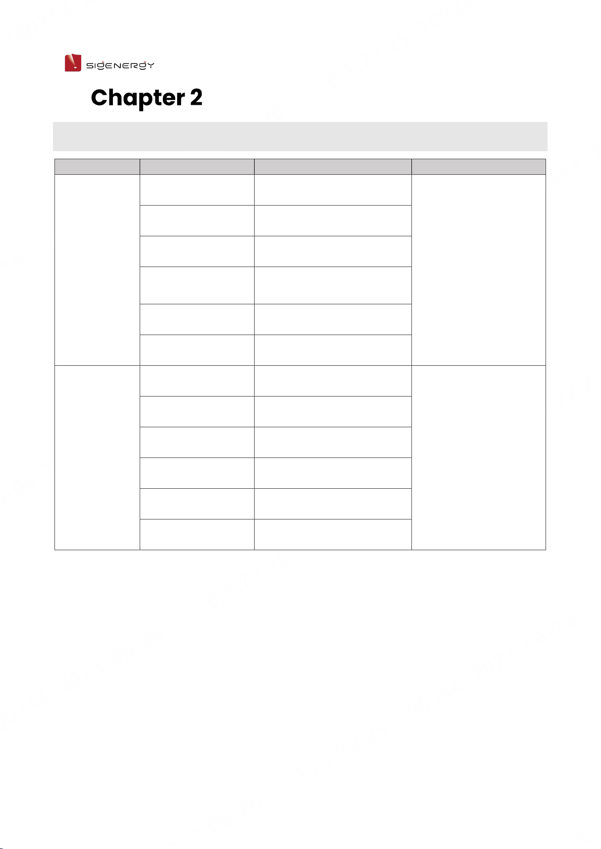
2.1 Product Model No.
Product code
Model No.
Name
Function specification
Sigen PV Max
Sigen PV Max 3.0 SP Sigen PV Inverter Max 3.0 kW
Single Phase
Single-phase string-
type PV grid-connected
inverters are designed
to convert the DC
electricity generated by
PV strings into AC
electricity for electric
equipment or feeding
into the grid.
Sigen PV Max 3.6 SP
Sigen PV Inverter Max 3.6 kW
Single Phase
Sigen PV Max 4.0 SP Sigen PV Inverter Max 4.0 kW
Single Phase
Sigen PV Max 4.6 SP Sigen PV Inverter Max 4.6 kW
Single Phase
Sigen PV Max 5.0 SP Sigen PV Inverter Max 5.0 kW
Single Phase
Sigen PV Max 6.0 SP Sigen PV Inverter Max 6.0 kW
Single Phase
Sigen Hybrid
Sigen Hybrid 3.0 SP Sigen Hybrid Inverter 3.0 kW
Single Phase
Inverter; it can be used
in conjunction with PV
modules for pure PV
applications or in
combination with PV
modules and SigenStor
BAT for photovoltaic
storage systems after
the purchase and
activation of a license.
Sigen Hybrid 3.6 SP Sigen Hybrid Inverter 3.6 kW
Single Phase
Sigen Hybrid 4.0 SP Sigen Hybrid Inverter 4.0 kW
Single Phase
Sigen Hybrid 4.6 SP Sigen Hybrid Inverter 4.6 kW
Single Phase
Sigen Hybrid 5.0 SP Sigen Hybrid Inverter 5.0 kW
Single Phase
Sigen Hybrid 6.0 SP Sigen Hybrid Inverter 6.0 kW
Single Phase

9/ 22
User Manual
2.2 Appearance Introduction
Appearance and Dimensions
Port Introduction
Serial No.
Name
Marking
1
Dc switch
DC SWITCH
2
Decorative cover light strip connector
LED
3
Antenna interface
ANT
4
Cable interface
RJ45 1/ RJ45 2
5
AC output interface
AC
6
Ground screw
-
7
Communication interface
COM
8
Sigen CommMod interface
4G
9
DC input interface
PV1+/PV2+/ PV1-/PV2-
10
(Reserved) Switch button
ON/OFF
10 / 22
User Manual
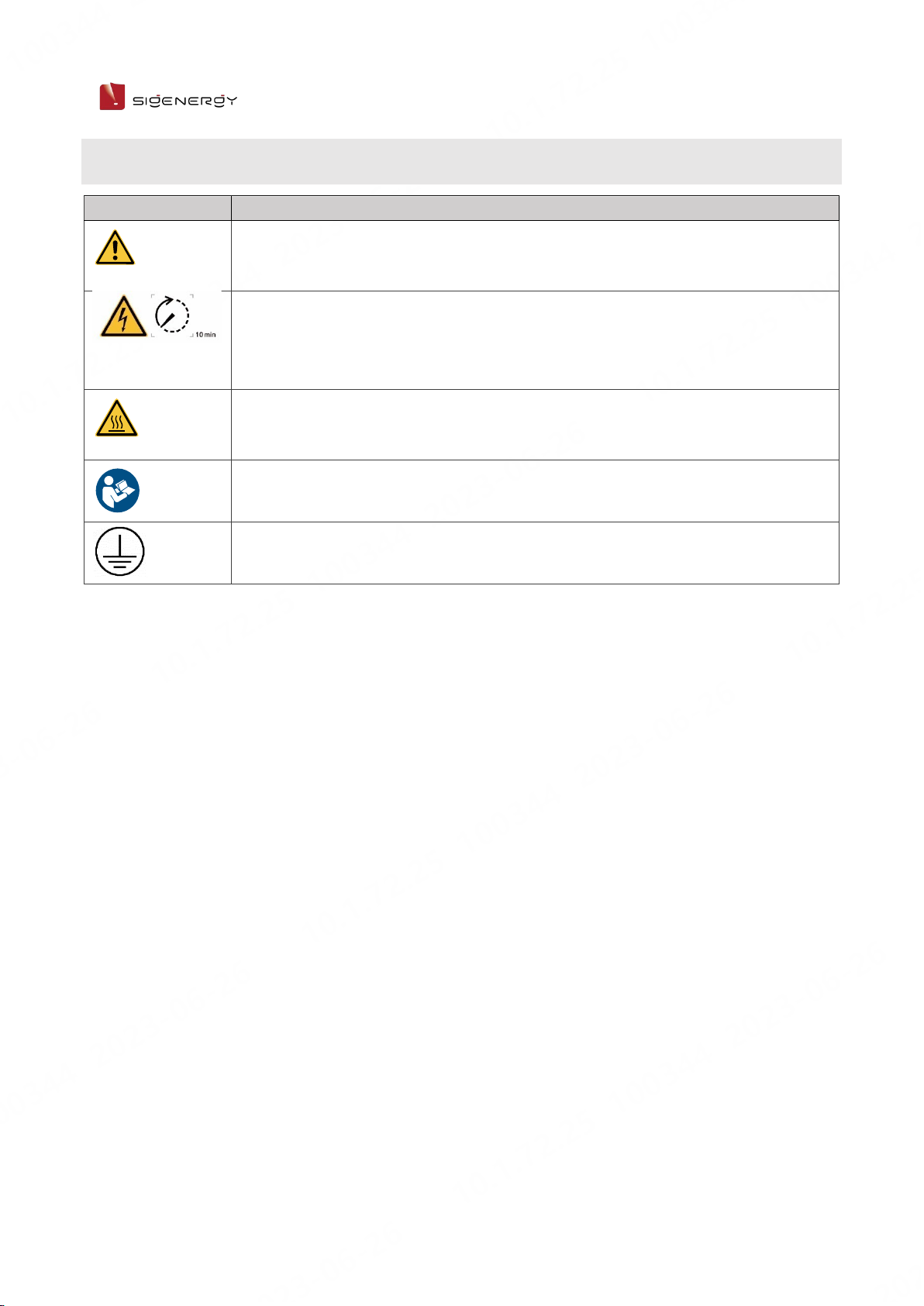
2.3 Label Description
Symbols
Definition
Warning! Life at risk.
The inverter has potential hazards after running. Take proper protection
when operating the inverter.
After the inverter is powered off, the discharge of internal components is
delayed. Wait 10 minutes until the inverter is fully discharged according to
the label time.
Warning! Risk of burns.
The inverter surface is hot. Do not touch the inverter when it is running. Doing
so may result in burns.
Please refer to the instructions to operate the equipment.
Earthing mark
11 / 22
User Manual
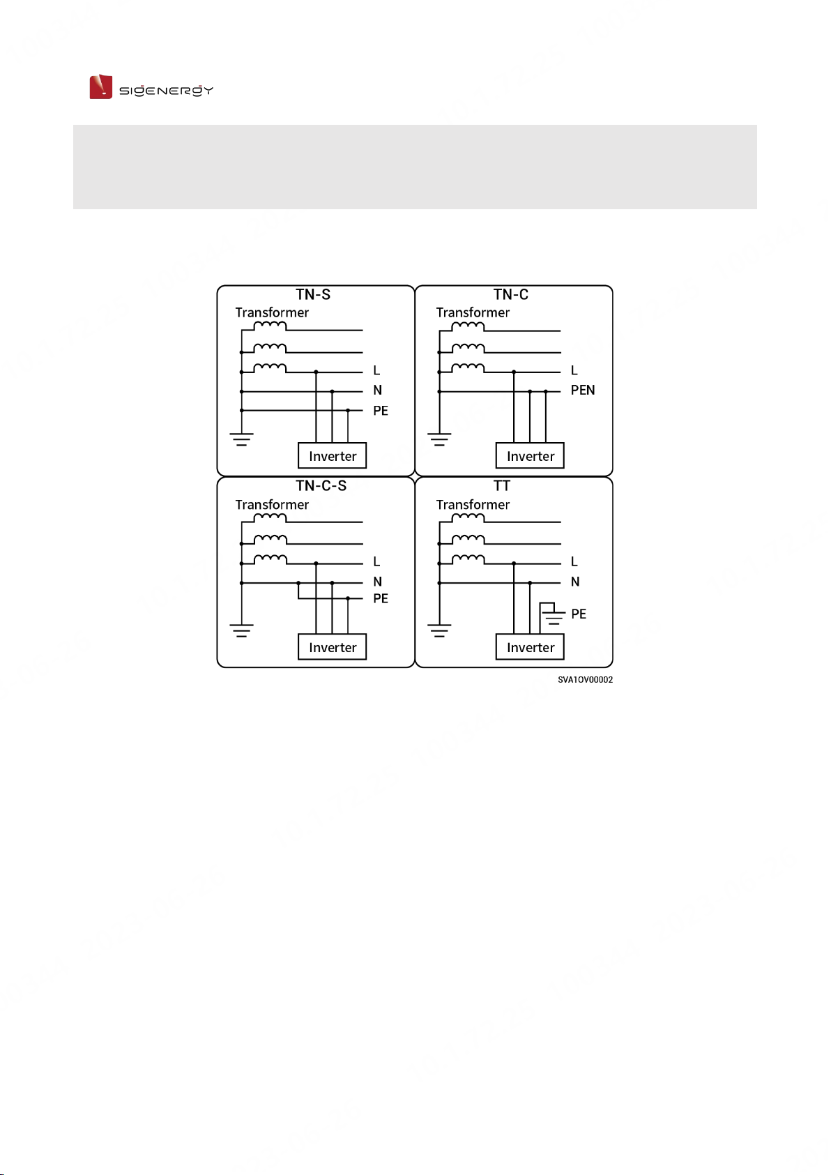
2.4 Supported Power Supply Methods for the Power
Grid
The grid supply methods supported by Sigen PV Max or Sigen Hybrid include TN-S, TN-C,
TN-C-S, and TT. When TT is used as the power supply technique for the power grid, the
voltage between N and PE is required to be < 30 V.

12 / 22
User Manual
2.5 Introduction to Typical Networking
Sigen PV Max or Sigen Hybrid is designed for grid-connected photovoltaic systems on
residential rooftops. The grid-connected system consists of photovoltaic strings,
inverters, distribution panels, and other components.
A. PV panel
B. Sigen PV Max or Sigen Hybrid
C. Electric equipment
D. AC distribution panel
E. Power sensor
F. Power grid
G. mySigen
H. Router
I. Antenna
J. CommMod
Sigen PV Max or Sigen Hybrid supports a maximum of 5 units in cascade connection.
It is recommended to use FE and WLAN for communication with inverter. CommMod
users must top up their own 4G data plan after a period of 2 years.
The rated voltage of the AC switch connected to each inverter should be ≥ 240 Va.c.
and the rated current is recommended:
Sigen PV Max/Sigen Hybrid (3.0-4.0) SP: The rated current is 25 A
Sigen PV Max/Sigen Hybrid (4.6-6.0) SP: The rated current is 40 A.

13 / 22
User Manual
Site Selection
Requirements
Installation Environment Requirements
Do not install the equipment in smoky, flammable, explosive, or corrosive
environments.
Do not install the equipment outdoors in areas prone to salt damage
area, which are located less than 500 meters from the coastline or
affected by sea wind.
Do not install the equipment in environments exposed to direct sunlight,
rain, standing water, snow accumulation, sand, and dust. It is
recommended to install in a sheltered location. If the area is susceptible
to natural disasters such as floods, landslides, earthquakes, or typhoons,
take preventive measures during equipment installation.
Do not install the equipment in an environment with strong
electromagnetic interference.
Ensure that the temperature and humidity of the installation environment
comply with the equipment's requirements.
Installation Position Requirements
Do not tilt or overturn the equipment to ensure that it is installed
horizontally.
Do not install the equipment in a place where children can easily reach it.
Do not install the equipment in areas subject to fire or moisture (including
but not limited to kitchen, tea room, toilet, shower room, laundry room,
etc.).
Please keep away from daily working and living areas (including but not
limited to living room, bedroom, studio, lounge, study, etc.).
Do not install the equipment in areas that are difficult to access
(including but not limited to attic, basement, etc.).

14 / 22
User Manual
Do not install the equipment in mobile scenarios such as
RVS, cruise ships, and trains.
You are advised to install the equipment in a position that is easy to
operate, maintain, and view indicator status.
When installing the equipment in the garage, do not install the equipment
in the position where the vehicle passes through to avoid collision.
Mounting Surface Requirements
Do not install the equipment on a flammable carrier.
The installation carrier must meet load-bearing requirements. Solid brick-
concrete structure, concrete walls, and ground are recommended.
The surface of the installation carrier must be smooth and the installation
area must meet the installation space requirements.
No water or electricity is routed inside the carrier to prevent drilling
hazards during equipment installation.

15 / 22
User Manual

16 / 22
User Manual
Equipment
Installation and Wiring
Only company authorized personnel should install and connect the equipment.
For details, see Sigen PV Max (3.0-6.0) SP, Sigen Hybrid (3.0-6.0) SP Installation
Guide.

17 / 22
User Manual
System Operation
5.1 LED Indicator State
Indicator
Color
State
Description
Always on
The DC side is connected but not running.
Always on
The DC side is running.
-
The DC side is not connected.
Flash
The DC side is faulty.
Always on
The inverter is faulty.
Always on
The AC side is connected but not running.
Always on
Grid-connected operation.
Always on
Off-grid operation.
-
The AC side is not connected.
Flash
Off-grid overload operation.
Flash
The AC side is faulty.
Always on
The inverter is faulty.
-
The management system is not connected.
Flash
Connected to local App.
Always on Connected to the management system using
an FE or WLAN.
Always on Connected to the management system over
4G.

18 / 22
User Manual
5.2 mySigen App Query
The App can be downloaded in the following two ways. For details, see mySigen
App User Manual.

19 / 22
User Manual
System Maintenance
6.1 Routine Maintenance
To ensure the long-term running of the equipment, you are advised to perform
routine maintenance according to this section.
Inspection
content
Inspection method Power off or
not
Maintenance
cycle
System cleaning
Check the device regularly for shielding
and dirt. If so, clean it up. Do not use tools
that may cause electric shock or insulation
damage, such as wire brushes and wet
towels during the cleaning process.
Yes
Once every
three months.
System running
state
Check whether the equipment is
damaged or deformed.
Listen for any abnormal noises during
the operation of the equipment.
When the equipment is running, check
whether the equipment parameters
are correctly set.
No Once every six
months.

20 / 22
User Manual
6.2 Equipment Powering-on/Power-off
Tap "Setting" in mySigen App to turn on/off the device.
This manual suits for next models
11
Table of contents
Popular Inverter manuals by other brands

SMA
SMA SUNNY TRIPOWER STORAGE X 30 Quick reference guide

Duracell
Duracell Pocket inverter 175 owner's guide

Nibe
Nibe UKVS 230 Installation and maintenance instructions

SDMO
SDMO TECHNIC 15000 TE Instruction and maintenance manual

Stober
Stober POSIDRIVE MDS 5000 Mounting instructions

Steamist
Steamist SM-46 installation instructions

Agilent Technologies
Agilent Technologies E8257D/67D installation guide

Schumacher
Schumacher PID-760 owner's manual

Toshiba
Toshiba Low Acoustical Noise Series Operation manual

Fenner
Fenner QD:E Series Installation and operating instructions

PrimeVOLT
PrimeVOLT PV 4K6HB-60 user manual

Silverline
Silverline 263764 manual


