SightLine EAN-USB Video Class User manual

© SightLine Applications, Inc.
EAN-USB Video Class (UVC) Cameras
2023-01-04
Exports: Export Summary Sheet
EULA: End User License Agreement
Web: sightlineapplications.com
1Overview ................................................................1
1.1 Additional Support Documentation.......................1
1.2 SightLine Software Requirements..........................1
1.3 Third Party Software ..............................................1
2Safe Device Handling..............................................1
34000-OEM USB Overview.......................................2
3.1 Connector J7: Debug only ......................................2
44000-OEM USB Camera Bench Setup ....................2
5Configuration Settings Overview ...........................3
5.1 Acquisition Settings................................................4
6Camera Discovery ..................................................4
7Advanced Configuration Options...........................6
7.1 Determining Supported Formats - Frame Rates -
Resolutions.............................................................6
7.2 Configuring Format - Frame Rates - Resolutions ...7
7.3 ELP-SUSB1080P01-LC1100 Webcam Configuration
Example..................................................................7
8FLIR Boson 640 Camera USB Interface...................9
8.1 RHP-BOSON VPC Interface Module - FLIR Boson
640 Camera............................................................9
8.2 FLIR VPS Kit - FLIR Boson 640 Camera..................10
8.3 Sierra-Olympic USB-C Adapter Board - DRS Tenum
640 Camera..........................................................11
8.4 FLIR Boson 640 and DRS Tenum Camera
Configuration Notes.............................................12
8.5 FLIR Boson 640 and DRS Tenum USB Camera Serial
Port Configuration ...............................................12
9Troubleshooting...................................................13
9.1 Questions and Additional Support.......................15
Appendix A: 4000-OEM Dual USB Camera Limitations and
Troubleshooting .............................................................15
Appendix B - USB Use Case Scenarios ............................16
B1 Use Case: USB to RS-232......................................16
B2 Use Case: USB Hubs .............................................16
B3 Use Case: Cameras with Serial Ports....................16
B3 Use Case: USB GPS...............................................17
CAUTION: Alerts to a potential hazard that may result in personal injury, or an unsafe practice that causes damage to the equipment
if not avoided.
IMPORTANT: Identifies crucial information that is important to setup and configuration procedures.
Used to emphasize points or remind the user of something. Supplementary information that aids in the use or understanding of the
equipment or subject that is not critical to system use.

EAN-USB-Video-Class-(UVC)-Cameras
© SightLine Applications, Inc. 1
1Overview
The USB Video Class (UVC) describes USB streaming video devices that comply with the USB video class
specification standards defined by the USB-IF. USB video class devices include webcams, still-image
cameras, analog video converters, digital camcorders, and transcoders.
This document describes how to configure the 4000-OEM to receive video from USB video class
cameras through the J8 USB 3.0 (Type-C) port.
For cameras that are based on the USB3 Vision standard see EAN-USB3-Vision-Cameras.
Before configuring the camera, it is important to know the type of USB camera being used. Check
the camera specification supplied by the manufacturer to determine the camera type.
1.1 Additional Support Documentation
Additional Engineering Application Notes (EANs) can be found on the Documentation page of the
SightLine Applications website.
The Panel Plus User Guide provides a complete overview of settings and dialog windows. It can be
accessed from the Help menu of the Panel Plus application.
The Interface Command and Control (IDD) describes the native communications protocol used by the
SightLine Applications product line. The IDD is also available as a PDF download on the Software
Downloads page.
1.2 SightLine Software Requirements
The 4000-OEM requires firmware 3.00.xx and higher.
IMPORTANT: The Panel Plus software version should match the firmware version running on the
board. Firmware and Panel Plus software versions are available on the Software Download page.
1.3 Third Party Software
Tera Term (recommended) or PuTTY: Terminal emulator programs used for debug output, or to issue
commands on SightLine hardware.
2Safe Device Handling
CAUTION: To prevent damage to hardware boards, disconnect all input power to OEMs and adapter boards before
connecting or disconnecting cables including all FFC, FPC, KEL, HDMI, MIPI, and round wire (Molex) cables.
CAUTION: To prevent damage to hardware boards, use a conductive wrist strap attached to a good earth ground.
Before picking up an ESD sensitive electronic component, discharge built up static by touching a grounded bare
metal surface or approved antistatic mat.

EAN-USB-Video-Class-(UVC)-Cameras
© SightLine Applications, Inc. 2
34000-OEM USB Overview
The J8 USB 3.0 (Type-C) port on the 4000-OEM can be used with USB Video Class (UVC) cameras. The
4000-OEM only supports dual USB cameras. This camera will appear as either CAM 2 or CAM 3.
IMPORTANT: The USB port (J8) should not be connected directly to a PC. This port cannot be used
for serial command and control directly.
USB 5V output can source 900mA max. 5V is also used for J9 connected MIPI interface boards and
combined maximum is 1.2A.
CAUTION: Do NOT connect an external 5V power source to the USB-C connector! Damage to the OEM may occur.
The 4000-OEM USB J8 port can also be used to connect to other USB devices:
•GPS devices
•USB to RS-232 converters
•Other devices that present themselves as serial ports such as the FLIR Boson 640 camera
•USB hubs
•Human Machine Interfaces (HMI) such as keyboards
•USB storage devices
Not all these devices are accessible from VideoTrack but should connect and enumerate in the Linux
OS. These devices can then be used by custom applications hosted on the processor.
3.1 Connector J7: Debug only
A USB 2.0 port is exposed on connector J7 and should only be used for serial debugging. This is not a
serial port that can be used for command and control, and it cannot be repurposed by another
application on the 4000-OEM.
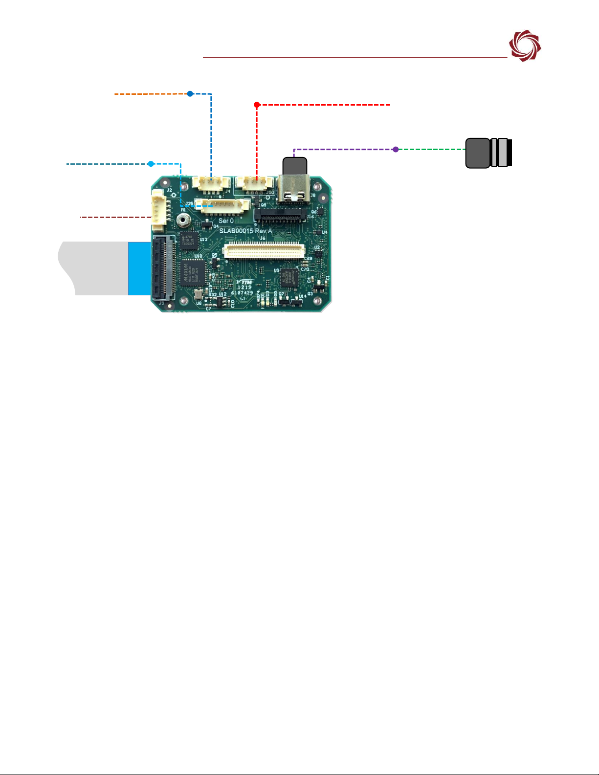
44000-OEM USB Camera Bench Setup
USB adapters:
•SLA-CAB-TC2USB (USB C to USB 3.0 Type-A Adapter) / camera specific USB 3.0 cable: Connects the
USB-C port (J8) on the 4000-OEM to USB video class cameras or other USB devices.
Cable connections:
•SLA-CAB-0403: Connects to J4 on 4000-OEM board. Provides an RJ45 Ethernet connection.
•SLA-CAB-1504 / SLA-PWR-B12V-36W (110-250VAC input / 12VDC output): Connects to J50 on the
4000-OEM board.
Power and network connectivity LEDs:
A green light (D1) on the 4000-OEM board indicates that all boards are powered on. An amber light
(D5) verifies network connection.
EAN-USB-Video-Class-(UVC)-Cameras
© SightLine Applications, Inc. 3
Figure 1: 4000-OEM USB Camera Bench Setup
*SLA-CAB-MIPI-02 FFC cable must be connected correctly. See the FFC cable instructions before connecting the SLA-4000-MIPI board.
**SLA-CAB-0305 can connect to SLA-CAB-0804 to facilitate a PC/USB connection to serial port 0 on the 4000-OEM. See the Serial
Communications section in the EAN-Startup-Guide-4000-OEM for more information.
Additional non-USB cameras can be connected to the 4000-OEM on J6 and using the SLA-4000-MIPI
board on J9. See the ICD-3000-4000 Adapter Boards for more information.
5Configuration Settings Overview
This section covers the basic camera configuration settings in Panel Plus for the 4000-OEM video
processing board.
See the EAN-Startup Guide 4000-OEM for connection and video streaming instructions.
For compatibly questions regarding specific camera models contact Support.
Before connecting with the Panel Plus software, the OEM board should be powered up and connected
through:
-a network switch or directly to the host PC (preferred) or,
-Direct serial connection (for troubleshooting or if a network connection cannot be established).
IMPORTANT: This procedure assumes that the customer has read the OEM startup guide and has a
basic understanding of the following fundamentals:
•Completed a functional connection between the SightLine video processing board and Panel
Plus application.
•Familiar with Panel Plus controls.
•Successfully streamed video in Panel Plus.
For help with basic connection and streaming fundamentals contact Support.
Network Switch or
PC Direct
SLA-CAB-1504 (J50)
Serial (SLA-CAB-0504)
SLA-CAB-0403 (J4)
4000-OEM
Optional
SLA-4000-MIPI Board
RJ45 Ethernet
SLA-PWR-B12V-36W
SLA-CAB-0804 (J25)
USB 3.0 Cable
(camera specific)
*SLA-CAB-MIPI-02 (J9)
USB Video Class
(UVC) Camera -
Other USB Devices
IMPORTANT: Disconnect all input
power to OEMs and adapter boards
before connecting or disconnecting
cables.
SLA-CAB-TC2USB (J8)
USB-C to USB 3.0 Adapter
**USB to Serial SLA-CAB-0305 (optional)
Contact
surface facing
down when
inserting.
EAN-USB-Video-Class-(UVC)-Cameras
© SightLine Applications, Inc. 4
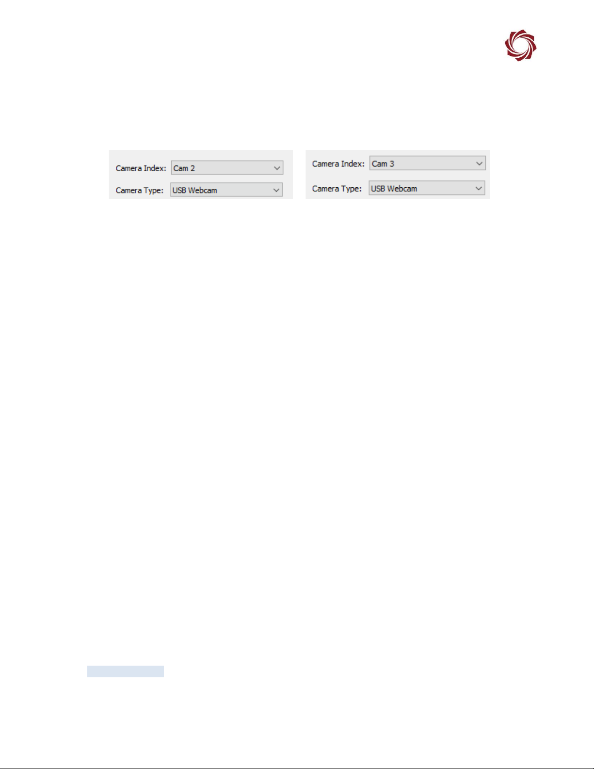
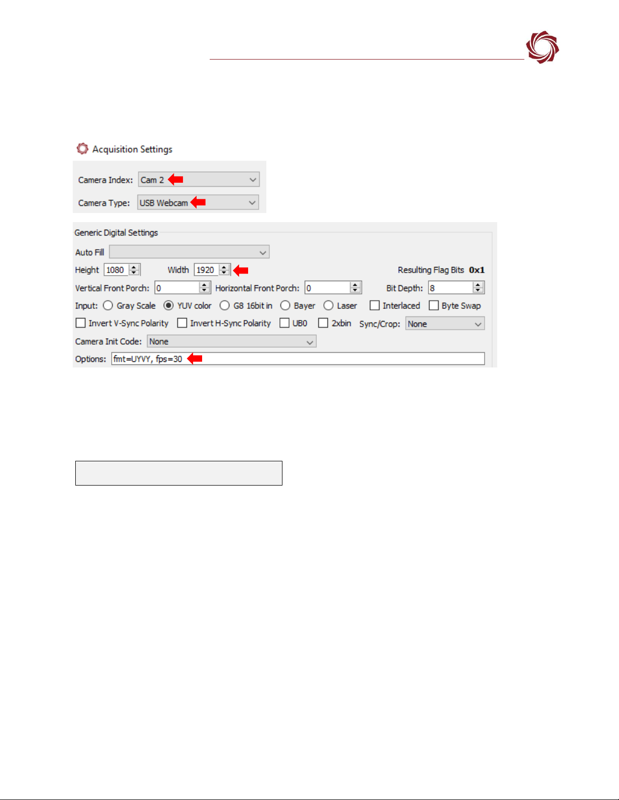
5.1 Acquisition Settings
1. From the main menu in Panel Plus go to Configure » Acquisition Settings.
2. In the Camera Index drop-down menu select Cam 2 or Cam 3.
3. In the Camera Type drop-down menu select USB Webcam.
Figure 2: Camera Index and Camera Type - USB Webcams
4. If available, use the Auto Fill drop-down menu in the Acquisition Settings dialog to automatically
populate the relevant fields with the correct settings.
The settings can also be manually entered as shown in the camera configuration table.
IMPORTANT: If the camera is not available in Panel Plus Auto Fill see the Camera Discovery section
to verify and modify camera resolutions, formats and frame rates that are available for a selected
camera.
For information about acquisition fields in Panel Plus see EAN-Digital Video Configuration.
IMPORTANT: Save parameters and reset the board when changing parameters. Cycle system
power when changing resolution.
If video does not display, try saving and activating the settings again. Check the encoding settings
on the Compress tab and review the network addresses for the destination video.
6Camera Discovery
See the basic camera configuration table for validated webcams. For compatibly questions regarding
specific camera models contact Support.
This section describes how to determine camera resolutions, formats, and frame rates that are
available for UVC cameras that are not preconfigured in Panel Plus Auto Fill.
Webcams normally send compressed video at full frame rate (e.g., 30 fps) or raw video at reduced
frame rate (e.g., 5 fps). Some models may send faster rate raw video. SightLine 4000-OEM boards are
compatible with UVC 1.1 and newer cameras.
Camera control can be done through the optArgs string argument to SetAcquisitionParameters (0x37)
or using the Options field in the Acquisition Settings dialog in Panel Plus.
1. Establish an SSH session to the OEM hardware with Tera Term.
Username and password for 4000-OEM is slroot.
2. Discover camera and device node name:
a. From the root@sla-alip:~# prompt type:
media-ctl -p
There can be multiple media devices enabled. The default is /dev/media0.

EAN-USB-Video-Class-(UVC)-Cameras
© SightLine Applications, Inc. 5
The console displays the device node name and camera name as shown in Figure 3. The device
node name can change between power cycles.
Figure 3: Discover Camera and Device Node Name
b. If the command in the previous step does not show the connected USB camera, search on other
media devices. To list available media devices, type:
ls /dev/media*
media-ctl -p -d /dev/mediaX (mediaX is media1 or media2)
Figure 4: USB Camera Search on Media Devices
c. As an alternate option to find the device node name, type:
v4l2-ctl --list-devices
Figure 5: Discover Camera and Device Node Name - Alternate Option
3. List available formats. From the root@sla-alip:~# prompt type:
v4l2-ctl --list-formats-ext -d /dev/video8
The resultant listing will show video format, resolution, and FPS support.
Figure 6: List Available Formats
Media device information
------------------------
driver uvcvideo
model HD Pro Webcam C920
serial 8EBCEE4F
bus info 1
hw revision 0x11
driver version 4.14.90
Device topology
- entity 1: HD Pro Webcam C920 (1 pad,1 link)
type Node subtype V4L flags 1
device node name/dev/video8
pad0: Sink
<- "Processing 3":1
[ENABLED,IMMUTABLE]
HD Pro Webcam C920 (usb-xhci-hcd.1.auto-1.4):
/dev/video8
ioctl: VIDIOC_ENUM_FMT
Type: Video Capture
[0]: 'YUYV' (YUYV 4:2:2)
Size: Discrete 640x480
Interval: Discrete 0.033s (30.000 fps)
Interval: Discrete 0.042s (24.000 fps)
Interval: Discrete 0.050s (20.000 fps)
Interval: Discrete 0.067s (15.000 fps)
Interval: Discrete 0.100s (10.000 fps)
Interval: Discrete 0.133s (7.500 fps)
Interval: Discrete 0.200s (5.000 fps)

EAN-USB-Video-Class-(UVC)-Cameras
© SightLine Applications, Inc. 6
4. Show current format. From the root@sla-alip:~# prompt type:
v4l2-ctl --all -d /dev/video8
Figure 7: Show Current Format
7Advanced Configuration Options
7.1 Determining Supported Formats - Frame Rates - Resolutions
1. Use Tera Term to establish an SSH session to the target.
2. Type the command:
v4l2-ctl --list-formats-ext -d /dev/video0
/dev/video0 may be replaced with /dev/videoN where N is 0 to 10.
In this example the camera supports UYVY and MJPEG formatted video transfer at various
resolutions and frame rates.
Figure 8: USB Webcam Supported Formats, Frame Rates and Resolutions
Priority: 2
Video input : 0 (Camera 1: ok)
Format Video Capture:
Width/Height : 1920/1080
Pixel Format : 'YUYV' (YUYV 4:2:2)
Field : None
Bytes per Line : 3840
Size Image : 4147200
Colorspace : sRGB
Transfer Function : Default (maps to sRGB)
YCbCr/HSV Encoding: Default (maps to ITU-R 601)
Quantization : Default (maps to Limited Range)
Flags :
Crop Capability Video Capture:
Bounds : Left 0, Top 0, Width 1920, Height 1080
Default : Left 0, Top 0, Width 1920, Height 1080
Pixel Aspect: 1/1
Selection: crop_default, Left 0, Top 0, Width 1920, Height 1080, Flags:
Selection: crop_bounds, Left 0, Top 0, Width 1920, Height 1080, Flags:
Streaming Parameters Video Capture:
Capabilities : timeperframe
Frames per second: 5.000 (5/1)
EAN-USB-Video-Class-(UVC)-Cameras
© SightLine Applications, Inc. 7
7.2 Configuring Format - Frame Rates - Resolutions
1. From the main menu in Panel Plus » Configure » Acquisition Settings.
2. Choose format and frame rate with the string in the Options field, e.g., <fmt=UYVY, fps=30>.
3. Click Apply. Main menu » Parameters » Save to Board.
4. Main menu » Reset » Board.
5. After the system reboots reconnect to the board. Make sure the board connects. In the bottom
status bar in Panel Plus main window, verify that the frame rate is as expected.
If the Options filed is left empty, the system will look for a supported format in the following order:
MPEG2, MPEG4, H264, H265, MJPEG, NV12, YUYV, UYVY, YUV420.
If an unsupported format is chosen, the camera will not capture video. If an unsupported frame rate
is chosen, the closest frame rate to the one chosen will be selected.
7.3 ELP-SUSB1080P01-LC1100 Webcam Configuration Example
This example describes how to determine formats, frame rates, and resolutions for the ELP-
SUSB1080P01-LC1100 UVC USB webcam.
Before starting, verify the camera is operating correctly using the Windows camera app. Connect
the camera to a PC running Windows and run the camera app. If video is being displayed the
camera is working.
1. Verify the camera is properly connected to the 4000-OEM. Since the USB port on the 4000-OEM is
a USB-C, a USB 3.0 to USB-C adapter is required to connect the camera to the board (SLA-CAB-
TC2USB).
2. Apply power to the board.
Streaming Camera: 2. Commanded Camera: 2
Frame Rate: 29.99.14 [frames/sec]. Data rate: 3043.31
[Kb/sec]
EAN-USB-Video-Class-(UVC)-Cameras
© SightLine Applications, Inc. 8
3. Use Tera Term to establish an SSH session to the OEM board.
Username and password is slroot
4. From the root@sla-alip:~# prompt type: lsusb
This step verifies that the device is connected and detected. The camera is on the same bus as the
USB 3.0 root hub. This enables the camera to reach USB 3.0 speeds.
Figure 9: Verify Device Connection and Detection
5. Find the camera and device node shown in the Camera Discovery section.
The camera is available on /dev/video8 shown in Figure 11.
Figure 10: Camera and Device Node Name
6. Follow the steps in the Determining Supported Formats - Frame Rates - Resolutions section to list
available formats for this device.
This camera supports MJPEG and YUYV output formats, at 1920x1080, 1280x720, and 640x480
shown in Figure 12. While the list suggests a maximum framerate of 60 fps, the manufacturer
advertises the camera as reaching a framerate of 50 fps. In this example 50 fps will be the frame
rate target.
Figure 11: Available Formats
Bus 002 Device 004: ID 15aa:1555 Gearway Electronics (Dong Guan) Co., Ltd.
Bus 002 Device 001: ID 1d6b:0003 Linux Foundation 3.0 root hub
Bus 001 Device 001: ID 1d6b:0002 Linux Foundation 2.0 root hub
Media controller API version 4.14.90
Media device information
------------------------
driver uvcvideo
model 3.0 USB Camera: 3.0 USB Camera
serial
bus info 1
hw revision 0x1002
driver version 4.14.90
Device topology
- entity 1: 3.0 USB Camera: 3.0 USB Camera (1 pad, 1 link)
type Node subtype V4L flags 1
device node name /dev/video8
pad0: Sink
<- "Extension 4":1 [ENABLED,IMMUTABLE]
ioctl: VIDIOC_ENUM_FMT
Type: Video Capture
[0]: 'MJPG' (Motion-JPEG, compressed)
Size: Discrete 1920x1080
Interval: Discrete 0.017s (60.000 fps)
Size: Discrete 1280x720
Interval: Discrete 0.017s (60.000 fps)
Size: Discrete 640x480
Interval: Discrete 0.017s (60.000 fps)
[1]: 'YUYV' (YUYV 4:2:2)
Size: Discrete 1920x1080
Interval: Discrete 0.017s (60.000 fps)
Size: Discrete 1280x720
Interval: Discrete 0.017s (60.000 fps)
Size: Discrete 640x480
Interval: Discrete 0.017s (60.000 fps)

EAN-USB-Video-Class-(UVC)-Cameras
© SightLine Applications, Inc. 9
7. Configure Acquisition Settings through Panel Plus as shown in the camera configuration table for
the ELP-SUSB1080P01-LC1100 camera:
a. Set Camera Index to Cam 2 and Camera Type to USB Webcam.
b. Set Auto Fill to USB Webcam 1080P.
c. Click Apply.
d. From the main menu in Panel Plus » Parameters » Save to Board.
e. Main menu » Reset » Board.
f. From the Connect tab reconnect to the board. Select Video Output » Cam 2.
g. Click Stream Network Video to This PC to see output video.
8. Check the frame rate at the bottom of the Panel Plus window. In this configuration the frame rate only
reaches ~20 fps.
9. Test available output formats for increasing the frame rate. In the Acquisition Settings dialog add a
format specifier to the Options field. For more information on this field see
SetAcquisitionParameters (0x37) in the IDD. In this example the MPEG output is tested.
a. In the Options field type the options string: fmt=MJPEG.
b. Click Apply.
c. Main menu » Parameters » Save to Board.
d. Main menu » Reset » Board.
10. Check the frame rate at the bottom of the Panel Plus window. In this configuration the frame rate only
reaches ~20 fps.
Repeat the above steps and use the option string fmt=YUYV to test the YUYV format. Check the
frame rate at the bottom of the Panel Plus window. In this configuration the frame rate reaches ~50 fps.
8FLIR Boson 640 Camera USB Interface
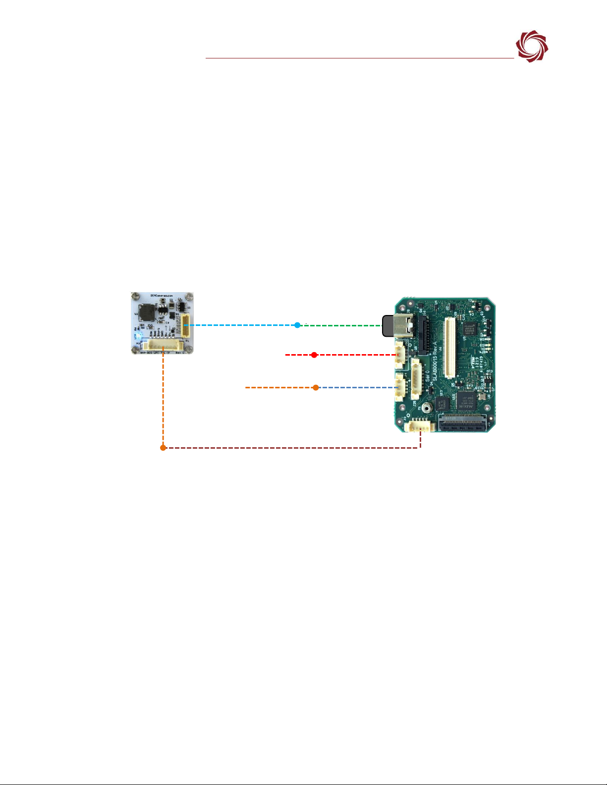
8.1 RHP-BOSON VPC Interface Module - FLIR Boson 640 Camera
OEM Cameras provides a USB interface for the FLIR Boson 640 camera to the 4000-OEM through the
RHP-BOSON VPC TTL interface module.
The custom cable harnesses included in the kit provide 3.3V TTL serial communication for command
and control, USB for video streaming, and external power.
Streaming Camera: 2. Commanded Camera: 2
Frame Rate: 22.86[frames/sec]. Data rate: 5667.38[Kb/sec]
Streaming Camera: 2. Commanded Camera: 2
Frame Rate: 20.05[frames/sec]. Data rate: 5368.76[Kb/sec]
Streaming Camera: 2. Commanded Camera: 2
Frame Rate: 48.38[frames/sec]. Data rate: 5714.73[Kb/sec]
EAN-USB-Video-Class-(UVC)-Cameras
© SightLine Applications, Inc. 10
USB adapters:
•SLA-CAB-TC2USB (USB-C to USB 3.0 Type-A Adapter) / 6-pin JST to USB: Connects the USB-C port
(J8) on the 4000-OEM to the RPH-Boson VPC interface module.
Cable connections:
•SLA-CAB-0504: Serial Port/GPIO 4000-OEM (J2). Connects to the 7-pin JST PicoBlade pigtail.
•SLA-CAB-0403: Connects to J4 on 4000-OEM board. Provides an RJ45 Ethernet connection.
•SLA-CAB-1504 / SLA-PWR-B12V-36W (110-250VAC input / 12VDC output): Connects to J50 on the
4000-OEM board.
Power and network connectivity LEDs:
A green light (D1) on the 4000-OEM board indicates that all boards are powered on. An amber light
(D5) verifies network connection.
Figure 12: RHP-BOSON VPC TTL Interface Module - 4000-OEM USB Connection
8.2 FLIR VPS Kit - FLIR Boson 640 Camera
FLIR provides a USB-C interface for the FLIR Boson 640 camera to the 4000-OEM through a VPC Kit (PN:
421-0061-00).
USB adapters:
•SLA-CAB-TC2USB (USB C to USB 3.0 Type-A Adapter) / USB-C to USB-A cable: Connects the USB-C
port (J8) on the 4000-OEM to the USB-C camera adapter board.
Cable connections:
•SLA-CAB-0403: Connects to J4 on 4000-OEM board. Provides an RJ45 Ethernet connection.
•SLA-CAB-1504 / SLA-PWR-B12V-36W (110-250VAC input / 12VDC output): Connects to J50 on the
4000-OEM board.
Power and network connectivity LEDs:
A green light (D1) on the 4000-OEM board indicates that all boards are powered on. An amber light
(D5) verifies network connection.
Network Switch
or PC Direct
SLA-CAB-1504 (J50)
SLA-CAB-0504 (J2)
SLA-CAB-0403 (J4)
4000-OEM
6-pin JST to USB
RJ45 Ethernet
SLA-PWR-B12V-36W
USB-C to USB 3.0 Adapter
SLA-CAB-TC2USB (J8)
)
FLIR Boson 640 with RHP-BOSON
VPC TTL Interface Module
7-pin JST
PicoBlade
Pigtail
IMPORTANT: Disconnect all input power to OEMs and adapter boards
before connecting or disconnecting cables.

EAN-USB-Video-Class-(UVC)-Cameras
© SightLine Applications, Inc. 11
Figure 13: FLIR Boson 640 with FLIR USB VPC Kit - 4000-OEM USB Connection
8.3 Sierra-Olympic USB-C Adapter Board - DRS Tenum 640 Camera
Sierra-Olympic provides a USB-C interface for the DRS Tenum 640 camera to the 4000-OEM through a
USB-C adapter board.
USB adapters:
•SLA-CAB-TC2USB (USB C to USB 3.0 Type-A Adapter) / USB-C to USB-A cable: Connects the USB-C
port (J8) on the 4000-OEM to the USB-C camera adapter board.
Cable connections:
•SLA-CAB-0403: Connects to J4 on 4000-OEM board. Provides an RJ45 Ethernet connection.
•SLA-CAB-1504 / SLA-PWR-B12V-36W (110-250VAC input / 12VDC output): Connects to J50 on the
4000-OEM board.
Power and network connectivity LEDs:
A green light (D1) on the 4000-OEM board indicates that all boards are powered on. An amber light
(D5) verifies network connection.
Figure 14: DRS Tenum 640 with USB-C Adapter Board - 4000-OEM USB Connection
USB C to USB 3.0 Adapter
SLA-CAB-TC2USB (J8)
)
Network Switch
or PC Direct
SLA-CAB-1504 (J50)
SLA-CAB-0403 (J4)
4000-OEM
USB-C to USB-A Cable
RJ45 Ethernet
SLA-PWR-B12V-36W
FLIR Boson 640 with
FLIR VPC Kit
IMPORTANT: Disconnect all input power to OEMs and adapter boards
before connecting or disconnecting cables.
USB-C to USB 3.0 Adapter
SLA-CAB-TC2USB (J8)
)
Network Switch
or PC Direct
SLA-CAB-1504 (J50)
SLA-CAB-0403 (J4)
4000-OEM
USB-C to USB-A Cable
RJ45 Ethernet
SLA-PWR-B12V-36W
DRS Tenum 640 with Sierra-
Olympic USB-C Adapter Board
IMPORTANT: Disconnect all input power to OEMs and adapter boards
before connecting or disconnecting cables.

EAN-USB-Video-Class-(UVC)-Cameras
© SightLine Applications, Inc. 12
8.4 FLIR Boson 640 and DRS Tenum Camera Configuration Notes
•Connect the camera to PC and verify it is functioning using the camera control GUI.
•Use the camera control GUI to reset the camera to factory defaults to ensure compatibility.
•In Panel Plus Acquisition Settings use Cam 2 for Camera Index. For Camera Type use USB Webcam.
•In the Acquisition Settings dialog, the DRS Tenum USB camera and the FLIR Boson USB camera both
use the FLIR Boson 640 USB option in the Auto Fill drop-down menu. This automatically populates
the relevant fields with the correct settings.
•The Options field of the Acquisition Settings dialog can be used to change the image format
captured by the system. If no options are specified (recommended) the default capture will be the
raw full bit depth grayscale image.
The settings can also be manually entered as shown in the camera configuration table.
In the Video Output section of the Connect tab be sure to select CAM 2 as the Command Camera
when using SightLine video processing tools.
8.5 FLIR Boson 640 and DRS Tenum USB Camera Serial Port Configuration
In addition to video over USB the FLIR Boson 640 and DRS Tenum USB camera present a serial port to
the Linux OS for command and control. The 4000-OEM can be configured to pass through data to this
serial port. Command and control may be established through the following methods:
•FLIR Boson Application (v3.0) / DRS camera control GUI.
•User implementation of the FLIR Boson command packet (FLIR Serial Line Packet FSLP).
•User implementation of the Tenum command packet.
1. From the main menu in Panel Plus »
Configure » Serial Ports.
2. Select Port as /dev/ttySL0.
3. Configure the protocol for TCP Pass
Through.
A default baud rate of 115200 was used
for the FLIR Boson 640 in this example.
The actual baud rate may be different.
4. Click Send.
Figure 15: Configure Serial Ports
5. Save the parameters to the board and rest the board. Main menu » Parameters » Save to Board.
Main menu » Reset » Board.
The Reboot step can be combined with the reboot step of the acquisition setup.
6. The OEM is now configured to send and receive data over a TCP connection.
Other passthrough options such as Serial-to-Serial are also available. For more information see
EAN-Ethernet-and-Serial-Communication.
EAN-USB-Video-Class-(UVC)-Cameras
© SightLine Applications, Inc. 13
7. See Appendix C - Virtual Com Port Setup in EAN-Ethernet-and-Serial-Communication to set up the
virtual COM port.
8. Run the FLIR Boson Application on the host PC using the new virtual serial port.
IMPORTANT: When the Boson camera is connected to 4000-OEM and configured to pass through
data limited functionality is expected in the FLIR Boson application. Video will also not be available
in the application. Panel Plus can be used to view video. Other settings may not take affect
depending on the capture mode that was selected.
9Troubleshooting
Video issues:
•Video is not showing
false color.
•Video is saturated or
does not look as good
as the FLIR Boson
application.
•Some FLIR format
commands do not
change the video.
The default capture is raw gray scale. In the Acquisition Settings dialog, change the image
format using the Options field: fmt=NV12.
To verify device is
connected and
enumerated.
1. Apply power to the board.
2. Use Tera Term to establish an SSH session to the OEM board.
3. From the root@sla-alip:~# prompt type: lsusb
Figure 16: Verify Device Connected and Enumerated
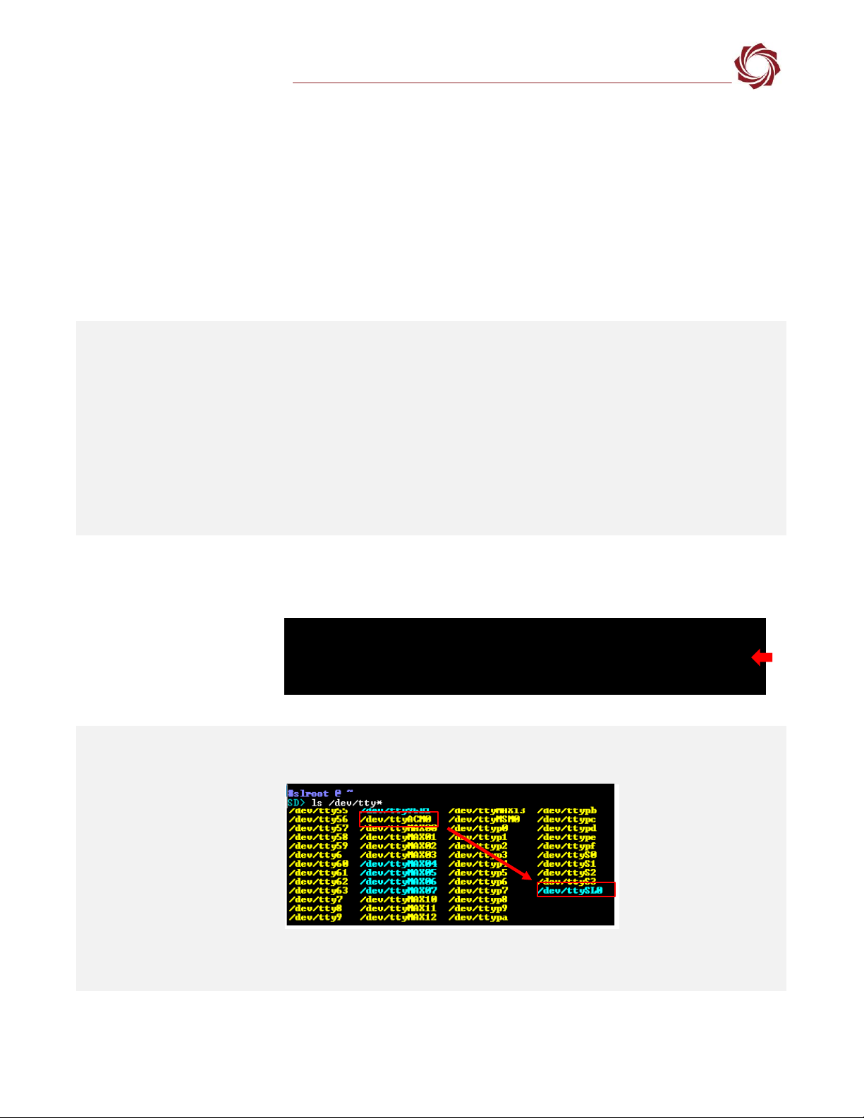
To verify serial -
(/dev/ttyACM0)
1. List the available serial devices. From the root@sla-alip:~# prompt type:
ls/dev/tty*
/dev/ttySL0 is a representational link to /dev/ttyACM0 that is automatically configured
by a udev rule.
Bus 002 Device 001: ID 1d6b:0003 Linux Foundation 3.0 root hub
Bus 001 Device 002: ID 044d:072d HD Pro Webcam (Camera is detected)
Bus 001 Device 001: ID 1d6b:0002 Linux Foundation 2.0 root hub
EAN-USB-Video-Class-(UVC)-Cameras
© SightLine Applications, Inc. 14
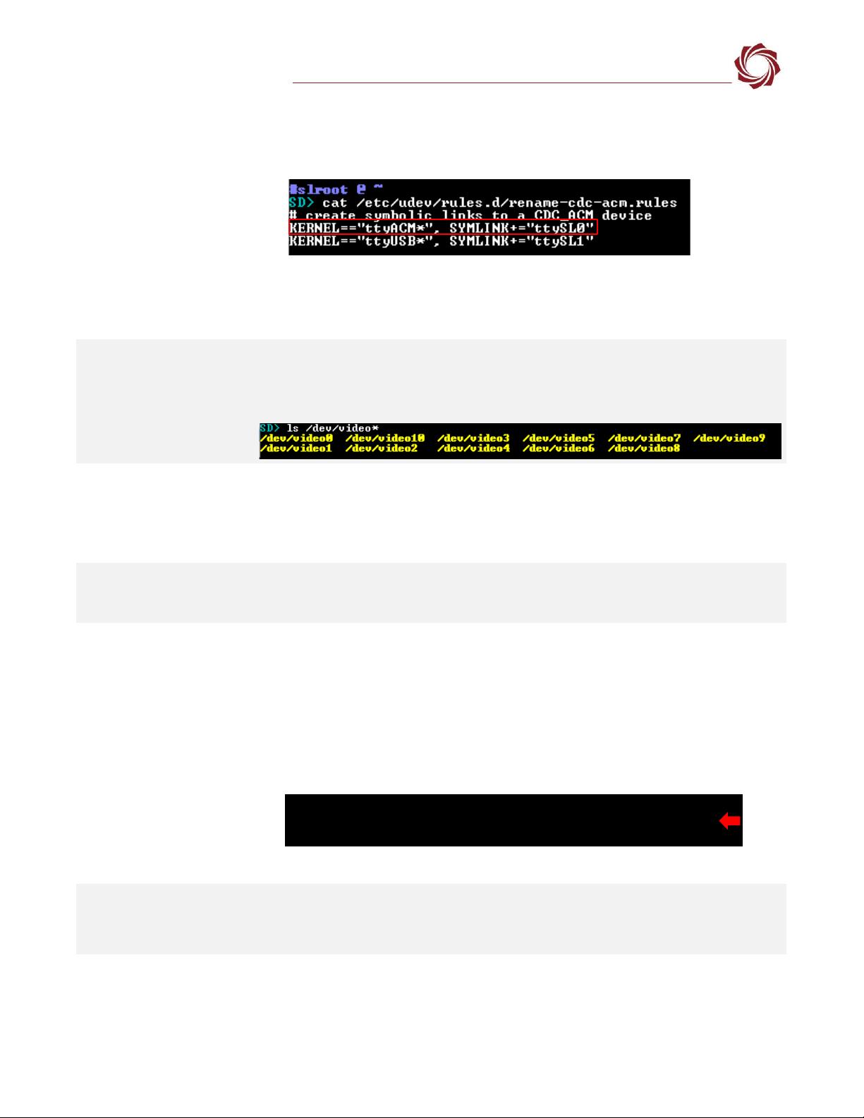
(Troubleshooting continued)
To verify the
/etc/udev/rules.d/rename-
cdc-acm.rules file exists.
Verify the contents of rename-cdc-acm.rules matches the following:
KERNEL==”ttyACM*”, SYMLINK+=”ttySL0”
The UDEV rule maps newly connected devices by matching the ttyACM* string to the
new ttySL0 device.
To verify video -
(/dev/videoN)
From the root@sla-alip:~# prompt type:
ls/dev/video*
The camera should list as a video device.
No Video, video quality is
bad, video artifacts.
Connect the camera to a Windows desktop and test the camera using the Windows
camera app. If any issues exist when the camera is connected to a Windows desktop and
4000-OEM, the issue may be the camera.
If using a USB-C to USB 3.0 adapter, unplug the adapter from the 4000-OEM USB-C input.
Turn it over and then plug it back in.
Check multiple input
modes.
If the camera supports multiple output formats, it can be valuable to test all available
formats for changes in performance and video quality. Follow the steps in the Camera
Discovery section to list available formats for this device.
Verify cables support the
USB camera.
Verify that all the cables or adapters used to connect the camera to the 4000-OEM support
the USB camera being used. If an adapter or hub that only supports USB 2.0 is used with a
USB 3.0 camera, the camera will not reach full framerate. Verify that the USB 3.0 camera
can reach USB 3.0 speeds by ensuring the camera is on the same bus as the USB 3.0 root
hub.
1. Apply power to the board.
2. Use Tera Term to establish an SSH session to the OEM board.
3. From the root@sla-alip:~# prompt type: lsusb
Figure 17: Verify USB Cable Support
Video flickering in ELP
camera configuration.
Check the connection quality of the USB cable to the camera.
The ELP camera has a default framerate of <30 fps. In the Acquisition Settings dialog
window make to use fmt=YUYV,fps=60 in the Options field.
Bus 002 Device 004: ID 155a:1515 HD Pro Webcam
Bus 002 Device 001: ID 1d6b:0003 Linux Foundation 3.0 root hub
Bus 001 Device 001: ID 1d6b:0002 Linux Foundation 2.0 root hub

EAN-USB-Video-Class-(UVC)-Cameras
© SightLine Applications, Inc. 15
(Troubleshooting continued)
Color artifacts in Kayeton
camera configuration.
Set False Color to White Hot from the Enhance tab in Panel Plus.
Alternately, in the Acquisition Settings dialog window, configure the camera for 480x640
out shown in Figure 19.
Figure 18: Kayeton 480 x 640 Camera Configuration
9.1 Questions and Additional Support
For questions and additional support, please contact SightLine Support. Additional support
documentation and Engineering Application Notes (EANs) can be found on the Support pages of the
SightLine Applications website.
Appendix A: 4000-OEM Dual USB Camera Limitations and Troubleshooting
In 3.5.x software and above Cam2 and Cam3 can both be configured for USB cameras, but have the
following are limitations:
•Both Cam2 and Cam3 cannot have a width greater than 1280 or a height greater than 720.
•When USB 2.0 cameras are used for Cam2 and Cam3, there is a bandwidth limitation of 480Mbps
resulting in unexpected framerates.
Some USB cameras that output video in a YUYV format, e.g., the Logitech C615 webcam, exceed the
required bandwidth limitation and may not be compatible with a dual USB camera configuration.
Framerate troubleshooting:
With both cameras connected to the 4000-OEM, start video track. If the following error message
displayed in the terminal window:
FATAL: VIDIOC_STREAMON returned error -1
VIDIOC_STREAMON: No space left on device
Try lowering the framerate of each camera using the following steps:
1. Panel Plus main menu » Configure » Acquisition Settings.

EAN-USB-Video-Class-(UVC)-Cameras
© SightLine Applications, Inc. 16
2. From the Camera Index drop-down menu select the index for one of the connected cameras.
3. In the Options field enter fps= followed by the new framerate, e.g., fps=24.
4. Click Apply.
5. Repeat the above steps for each camera. The video feed should display.
6. If video is still not displaying, see if the error message was output to video track in the terminal
window.
7. If the error message persists, try lowing the resolution of one or both cameras:
a. Panel Plus main menu » Configure » Acquisition Settings.
b. From the Camera Index drop-down menu select the index for one of the connected cameras.
c. Enter a resolution in the Height and Width fields.
d. Click Apply. The video feed should display.
8. If the same error message persists, try swapping one or both cameras for a different camera.
9. Reboot the 4000-OEM.
10. In an SSH connection verify that /dev/video14 and /dev/video15 devices have been created by
executing ls -l /dev/video*.
11. If they have not been created, try disconnecting and reconnecting the video devices, and/or
rebooting the 4000-OEM again.
Appendix B - USB Use Case Scenarios
B1 Use Case: USB to RS-232
The USB port (J8) cannot be connected directly to a PC. This port also cannot be used for SightLine
serial command and control. However, a USB to RS-232 device can be connected to the USB port. This
is accessible as /dev/ttySLn to VideoTrack and as a normal COM port to the PC. /dev/ttySLn can then
be set for SightLine protocol for command and control or any other protocol.
B2 Use Case: USB Hubs
A USB hub can be connected to the 4000-OEM to extend the number of devices that the system can
use.
SightLine recommends that any USB hub be powered separately to provide enough power to those
connected devices.
B3 Use Case: Cameras with Serial Ports
USB webcams can present as both a camera (Cam 2) and a serial port (/dev/ttySL0). In this case, the
camera can be setup as a standard USB webcam and the serial port can be configured for any SightLine
protocol such as TCP passthrough. This would allow for commands to be sent from a client (PC or
similar device) to the SightLine system and then sent to the camera. Data from the camera is then sent
back to the client.
There is some latency involved in this method and care should be taken for time critical applications.
EAN-USB-Video-Class-(UVC)-Cameras
© SightLine Applications, Inc. 17
B3 Use Case: USB GPS
The example described in this section uses the Onyehn VK-162 G-Mouse USB GPS dongle with the U-
blox UBX-G70xxx GNNS internal chip.
The Onyehn GPS device will output NMEA 0183 compatible strings that can be used as KLV Metadata
input to the SightLine system to setup up the following:
•Set the onboard clock for timestamped video and snapshots.
•Geotag snapshots with EXIF data.
•Output as STANG compatible KLV in the MPEG2-TS along with H.264/H.265 compressed video.
•Onscreen Display (OSD) graphics such as time, altitude, and location.
Configuration and setup:
1. Configure the hardware as shown
in 4000-OEM USB Camera Bench
Setup.
2. Use the SLA-CAB-TC2USB adapter
to the GPS device and the J8 on
the 4000-OEM.
3. Apply power to the 4000-OEM.
4. The GPS device will be powered
over USB.
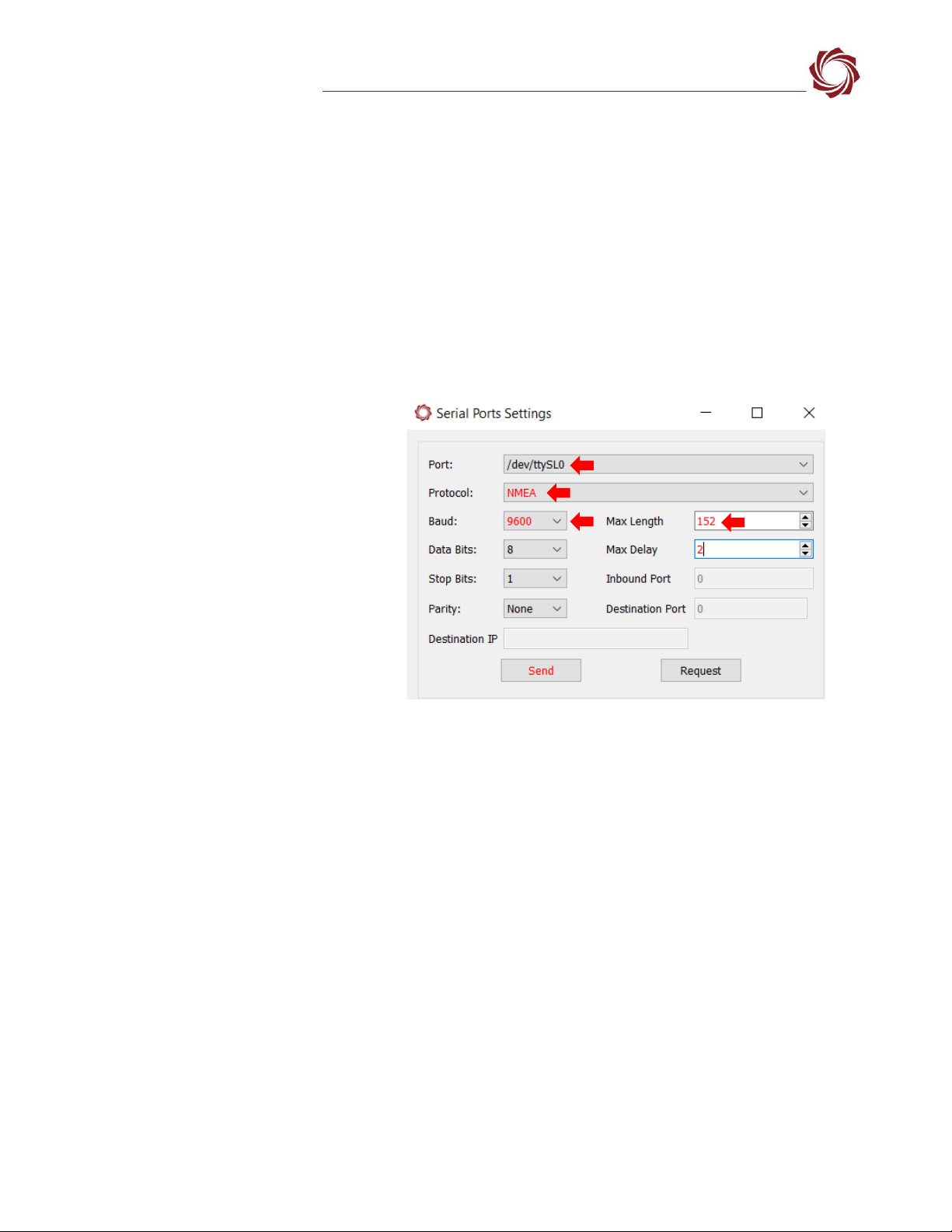
5. Configure the serial port settings.
Panel Plus Main menu »
Configure Serial Ports.
Figure B1: Serial Port Configuration - GPS Device Example
USB GPS device serial port configuration notes:
•The GPS device shows up as /dev/ttyACM0 in Linux file system. /dev/ttyACM0 is mapped to
/dev/ttySL0 (port ID == 11) for use in Panel Plus or SightLine Command and Control.
•Mapping is done through a UDEV rules file (<<file name here>>)
•See SetPortConfiguration (0x3E) for details on configuring serial port settings for ttySL0.
•In this example, the GPS baud rate is set to 9600. Other devices may default to other baud rates
(e.g., 4800 baud). Refer to GPS device documentation.
•This device will occasionally generate long strings rather than the usual 82 characters, so the max
length has been extended to 152 characters.
6. Configure metadata sources. From Panel Plus go to main menu » Configure » KLV Setup.
7. Use the KLV Data Fields dialog window to select the MISB Tag IDs and set the source to NMEA. See
EAN-KLV-Metadata for more information.

EAN-USB-Video-Class-(UVC)-Cameras
© SightLine Applications, Inc. 18
8. In Panel Plus confirm which output stream is being used and then click Send.
Figure B2: Configure Metadata Sources - Example
KLV data can also be used as on-screen display (OSD) overlays such as UTC, Latitude and Longitude,
etc. See the KLV Data Overlays section in the EAN-Overlay-Graphics for more information.
Confirm which output
stream is being used.
Table of contents
Other SightLine Digital Camera manuals


 instruction manual")


