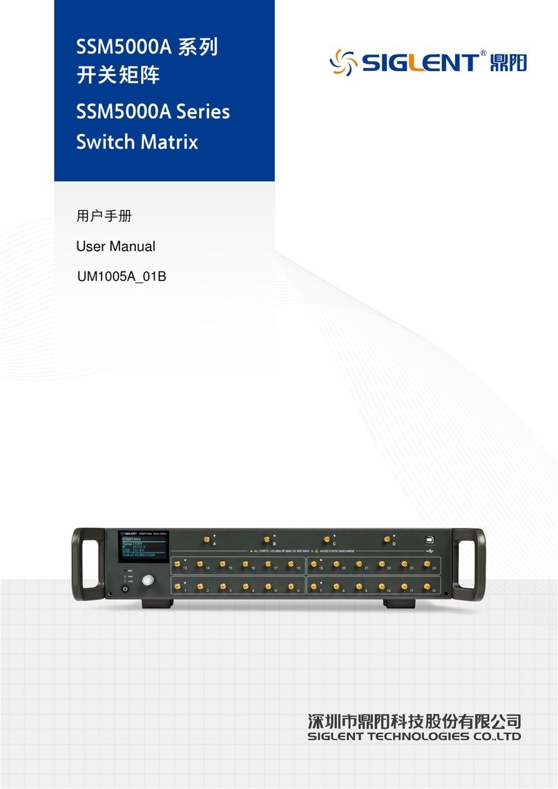
SIGLENT SSM5000A Series User manual

QS10050_E01A
SSM5000A series
Series
Switch Matrix
QuickStart
SIGLENT TECHNOLOGIES CO., LTD

SSM5000A Switch Matrix Quick Start 1
Contents
1. Copyright and statement...............................................................................................................2
2. General safety summary ................................................................................................................2
3. General inspection ...........................................................................................................................3
4. Preparing for use ..............................................................................................................................3
5. Front panel..........................................................................................................................................5
6. Rear panel ...........................................................................................................................................7
7. User interface.....................................................................................................................................8
8. Firmware operation ...................................................................................................................... 10
9. Help information ........................................................................................................................... 11
10. Remote control ...................................................................................................................... 11
11. Product certification............................................................................................................. 11
12. For more product information ......................................................................................... 11

2SSM5000A Switch Matrix Quick Start
1. Copyright and statement
SIGLENT TECHNOLOGIES CO., LTD All Rights Reserved.
SIGLENT is the registered trademark of SIGLENT TECHNOLOGIES CO., LTD.
SIGLENT products are protected by patent law worldwide.
Information in this publication replaces all previously corresponding material.
SIGLENT reserves the right to modify or change parts of or all the specifications or pricing
policies at the company’s sole decision.
Any method of copying, extracting or translating the contents of this manual is not allowed
without the permission of SIGLENT.
2. General safety summary
Carefully read the following safety precautions to avoid any personal injury or damage to
the instrument and any products connected to it. To avoid potential hazards, please use the
instrument as specified:
Only qualified technicians can carry out maintenance of the product.
Only the power cord designed for the instrument and authorized by the local country could
be used.
The instrument is grounded through the protective earth conductor of the power cord. To
avoid electric shock, please make sure the instrument is grounded correctly before
connecting its input or output terminals.
The potential of the signal wire ground is equal to the earth, so do not connect the signal
wire to a high voltage.
To avoid fire or electric shock, please look over all ratings and safety labels on the
instrument. Before connecting the instrument, please read the manual carefully to gain
more information about the ratings.
Do not touch exposed contacts or components when the power is on.
To avoid short-circuiting to the interior ofthe device orelectricshock,pleasedo notoperate
the instrument in a humid environment.
To avoid damage to the device or personal injury, it is important to operate the device away
from an explosive atmosphere.
To avoid the influence of dust and moisture in the air, please keep the surface ofthe device
clean and dry.
Safety terms and symbols:
Terms on the product, these terms may appear on the product.
DANGER: Indicates direct injuries or hazards that may happen.
WARNING: Indicates potential injuries or hazards that may happen.
CAUTION: Indicates potential damages to the instrument or other property that may
happen.

SSM5000A Switch Matrix Quick Start 3
Symbols on the product, these symbols may appear on the product:
Hazardous Voltage Warning Protective Ground Earth Chassis Ground
3. General inspection
Inspect the shipping container:
Keep the shipping container or cushioning material until the contents of the shipment
have been completely checked and the instrument has passed both electrical and
mechanical tests. The consigner or carrier will be responsible for damages to the
instrument resulting from shipment. SIGLENT will not provide free maintenance or
replacement
Inspect the instrument:
If the instrument is found to be damaged, defective, or fails in electrical or mechanical
tests, please contact SIGLENT.
Check the accessories:
Please check the accessories according to the packing list. If the accessories are
incomplete or damaged, please contact your SIGLENT sales representative.
4. Preparing for use
Dimensions:
Figure 4-1 Front View (unit: mm)

4SSM5000A Switch Matrix Quick Start
Figure 4-2 Top View (unit: mm)
Adjust the supporting legs:
For benchtop operation, you may want to use the supporting legs.Adjust the supporting
feet appropriately to tilt the equipment upwards.

SSM5000A Switch Matrix Quick Start 5
Figure 4-3 adjusting of supporting legs
Connect to AC power supply:
The equipment accepts 100-240 V, 50/60/400HzAC power supply. Please use the power
cord provided in the accessory to connect the instrument to the power source
5. Front panel
Figure 5-1 Front panel
Table 5-1 Front panel area description:
No.
Items
Description
A
LCD Screen
2.4inch LCD screen.
Notes: Avoid touching the LCD screen with sharp objects.
B
RF Ports A-D
3.5mm female RF ports, source group, usually connect to the other
instrument such as VNA, SA and so on.
C
RF Ports 1-24
3.5mm female RF ports, extended group, usually connect to the
DUT.
D
USB Hub
USB port for host remote control.
E
Reset
Reboot system

6SSM5000A Switch Matrix Quick Start
F
Indicator Lights
Warning indicator and LAN config indicator.
G
Power Switch
Power on/off.
H
Knob
Rotate the knob left or right to move a cursor (position of selected
item) or change a parameter value, the effect of pressing the knob
is the same as ‘Enter’.
Power switch:
Light-off indicates that the instrument is in the stand-by state. Pressing this button will
cause the instrument to begin the start-up process and the power switch light will turn
white.
A White light constantly on indicates the instrument is in the operating state. A short press
will cause the instrument to save the current settings and then return to the stand-by state
and the light will turn Off.
RF connectors:
Figure 5-2 Front panel RF connectors
There are two groups of RF connectors. A-D are the source group, 1-24 are the extended
group. A and B could be connected to one of 1-6 or 13-18 ports, but A and B can’t be
connected to the same number port simultaneously. Such as C and D ports, the number
of ports can be connected to are 7-12 and 19-24.
When a couple of RF connector are linked together, the corresponding port lights above
the RF connectors will be lit up with the same color.
Toavoid damageto theinstrument,theRF connectorinputsignalmust meetthefollowing:
The DC voltage and the maximum continuous RF power cannot exceed 35V and 20 dBm
respectively.

SSM5000A Switch Matrix Quick Start 7
6. Rear panel
Figure 6-1 Rear panel
Table 6-1 Rear panel area description:
No.
Items
Description
A
Direct
CTRL
Uses TTL voltage to control switches.
B
LAN
Network port for host to remote control
C
USB
Plugged with U-disk for version upgrading.
USB
Device
USB port for data exchange with peripherals.
D
Fan
Used to cool down internal components of the instrument.
E
AC Power
Port and
Fuse
The equipment accepts 100-240V, 50/60/400Hz AC power supply.
Pleaseconnecttheequipmentto theAC powersupplywiththe supplied
power cord. Make sure the current does not exceed the rated current
of the fuse.
F
Handle
Portable handle to carry the instrument conveniently.

8SSM5000A Switch Matrix Quick Start
7. User interface
Table 7-1 User interface description:
Menu
Illustration
Function description
Status
Display
The first display when instrument starts up. Display the
model, serial number, IP address, USB port status, RF
ports link status. Push the knob in this display will enter
the first setting menu.
1’st setting menu
Includes 4 sub-menus.Rotating the knob will select one of
them, then pushing knob will enter the selected sub-menu.
System menu
Display startup times, vendor, model, SN, soft version,
mainboard temperature.
Port menu
Set the link config of ports. Four steps to config:1. Rotate
the knob to select one of the four ports(A-D); 2. push the
knob to enter the config mode; 3. Rotate the knob to
change the number of linked port;4. push theknob to finish
setting and return.
IP menu
The instrument supports DHCP and static IP modes.
Rotate and push theknob to enter the mode setting (on/off
item). When OFF (Static IP) is selected, Rotate and push
the knob to config IP/SUB/GATE address.
Upgrade menu
When U-disk with version file is plugged, enter the
Upgrade menu to upgrade the system.

SSM5000A Switch Matrix Quick Start 9

10 SSM5000A Switch Matrix Quick Start
8. Firmware operation
Check system information
Enter the System sub-menu to check the system information, including:
Startup times
Vendor
Product model
Serial number
Software version
Mainboard temperature
Firmware upgrade
Follow this procedure to update the instrument firmware
1. Download the firmware package from official SIGLENT websites only.
2. Extract and copy the .ADS file into the root directory of a USB stick.
3. Insert the USB stick into a USB port, Enter Upgrade, and select the update file, click OK to
update the system software.
4. The progress bar will appear on the screen while updating, the instrument will restart
automatically if updates succeed or display a pop-up prompt box if updates fail.
Note: Please ensure that line power is constant during the upgrade by using an
Uninterruptible Power Supply (UPS), Failure to maintain line power may be cause
upgrade failure or instrument damage.

SSM5000A Switch Matrix Quick Start 11
9. Help information
Connect our sales rep for more information and help.
10. Remote control
The switch matrix supports communication with compatible computers via USB and LAN
interfaces. By using these interfaces, in combination with programming languages and/ or NI-
VISA software, users can remotely control the switch matrix.
11. Product certification
SIGLENT guarantees this product conforms to the national and industrial standards in China
as well as the ISO9001: 2008 standard and the ISO14001: 2004 standard. Other
international standard conformance certification is in progress.
12. For more product information
You can obtain the instrument information and installation status of all options through Utility
menu, for more information of this product, please refer to the following manuals (you can also
download them from the SIGLENT web site):
SSM5000A Switch Matrix user manual:
Provides detailed introductions of the functions of this instrument.
SSM5000A Switch Matrix programming manual:
Provides detailed introductions of the SCPI commands and programming of this
instrument.
SSM5000A Switch Matrix Data Sheet:
Provides the main characteristics and specifications of this instrument.

12 SSM5000A Switch Matrix Quick Start
Table of contents
Other SIGLENT Matrix Switcher manuals
Popular Matrix Switcher manuals by other brands

Extron electronics
Extron electronics Crosstalk 1632 Specifications
Comprehensive
Comprehensive CSW-302PSMC Operation manual

WolfPack
WolfPack 4x4 user manual
Guntermann & Drunck
Guntermann & Drunck ControlCenter-Compact-16C Installation and operation manual
PureTools
PureTools PT-MA-HD44M user manual
Gefen
Gefen EXT-HDFST-848CPN user manual
