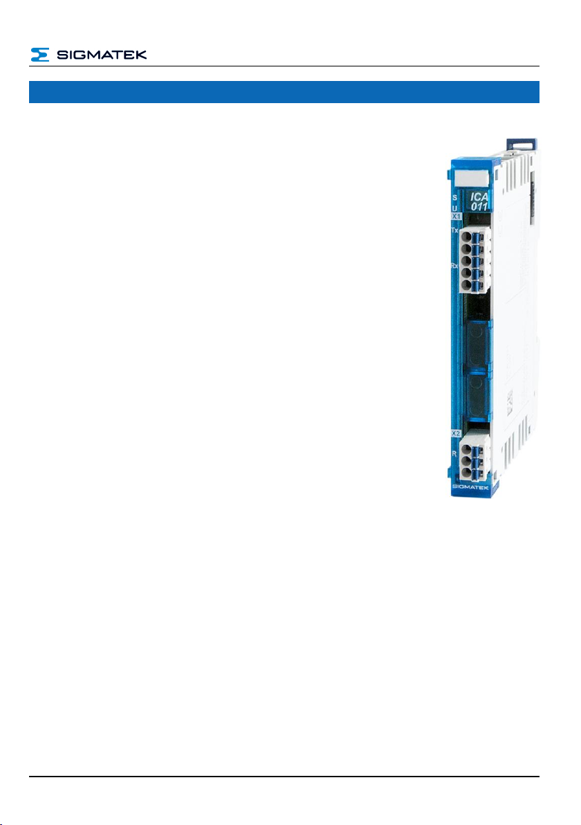
ICA 011 S-DIAS INTERFACE MODULE
Page 4 26.07.2023
9.4.16 ChkObjExists.....................................................................................42
9.4.17 DelCanObj.........................................................................................42
9.4.18 DelBasicCanObj................................................................................42
9.5 Asynchrones Interface...............................................................43
9.5.1 IsInstalled ..........................................................................................43
9.5.2 GetBaudrate......................................................................................43
9.5.3 SetBaudrate.......................................................................................44
9.5.4 AddCanObj........................................................................................44
9.5.5 InitBasicCanObject............................................................................45
9.5.6 CanTxObject......................................................................................45
9.5.7 AddCanObjExtended.........................................................................46
9.5.8 InitBasicCanObjectExtended.............................................................46
9.5.9 CanTxObjectExtended ......................................................................47
9.5.10 GetMyStation.....................................................................................47
9.5.11 SetMyStation.....................................................................................47
9.5.12 LoginIntoCanNew..............................................................................47
9.5.13 Set_RTR_Flag...................................................................................48
9.5.14 CanTxObjHandle...............................................................................48
9.5.15 CanRxObjHandle...............................................................................48
9.5.16 RedefCanObj.....................................................................................48
9.5.17 ChkObjExists.....................................................................................49
9.5.18 DelCanObj.........................................................................................49
9.5.19 DelBasicCanObj................................................................................49
9.6 Example of the interrupt function.............................................49
9.7 Type Description.........................................................................49
9.8 _BasicCanObj .............................................................................50