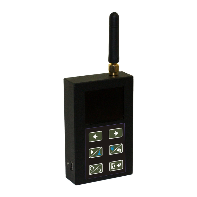
SIGNAL-T ST167W5 Manual

ST 167 “BETTA”
ST167W5
SEARCH RECEIVER
TECHNICAL DESCRIPTION AND
OPERATING MANUAL

Technical description and operating manual ST 167 and ST167W5
2
CONTENT
1
INTRODUCTION
3
2
FUNCTIONALITY
4
3
SPECIFICATIONS
5
4
COMPLETE SET
5
5
DESIGN AND OPERATION
6
5.1
OPERATION MODES
6
5.2
LABELS AND SEALING
6
5.3
PACKAGING
6
6
ST167 OPERATION
7
6.1
CONTROLS AND INDICATORS
7
6.2
POWER SUPPLY
8
6.3
"AUTOMATIC" OPERATION MODE
8
6.4
"MANUAL" OPERATION MODE
12
6.5
"SEARCH" OPERATION MODE
12
6.6
"EVENT LOG" OPERATION MODE
13
6.7
SMS\GPRS OPERATION MODE
14
6.8
«Wi-Fi» OPERATING MODE (only for ST167W5)
15
6.9
BASE STATIONS LEVEL MEASUREMENT
15
6.10
TRAFFIC
15
6.11
BLOCKER (Jammer) DETECTION
16
6.12
EXTERNAL DEVICES OPERATION (only for ST167R)
17
6.13 MENU
18
7 RECOMMENDATIONS
22
8
OPERATION WITH A COMPUTER
32
8.1
«ST167ANALYZER» SOFTWARE
32
8.2
FIRMWARE UPGRADE
32
9
LIMITATIONS AND RECOMMENDATIONS
32
10 WARRANTY
33
11 ACCEPTANCE CERTIFICATE
33

Technical description and operating manual ST 167 and ST167W5
3
1 INTRODUCTION
Present document contains information necessary for the proper use of ST167, ST167W5 (hereinafter –
ST167, if isn’t otherwise noted). Carefully read it before using and keep it as your further reference manual.
The information contained in this document is subject to change without notice.
The manufacturer reserves the right to make changes in the unit design as long as they do not decrease its
consumer properties.

Technical description and operating manual ST 167 and ST167W5
4
2 FUNCTIONALITY
ST167 is designed for:
•Detection, identification and localization of the sources of the following types of signals: cellular
standards (cellular phones and modems SDMA450, GSM 900, 1800, 3,4 and 5G), wireless data transmission
(WLAN 2.4 and 5GHz , BLUETOOTH) and microcellular wireless communication standard DECT.
All the devices mentioned above hereafter are referred to as DRT (digital radio transmitters).
Spectrogram standards indication is provided, including channels separation in 3G, 4G, WLAN and DECT
standards.
Data transmission intensity analysis is provided for the WLAN standard.
Special SMS detection mode is provided.
Furthermore, BASE STATIONS signal level indication in CDMA450, GSM 900, 1800, 3, 4, 5G and DECT
standards is possible.
Access points(routers) indication, their name, MAC address, used channel number and signal level in
WLAN 80.1 (a,b,g,n) range (only for ST167W5).
Detection and measurement of frequency, demodulation (AM and FM) and locating of the sources of
analog signals (hereinafter referred to as ART, i.e., analog radio transmitters). You can choose the
threshold, the scanning range and the sound control of the demodulated signals.
Blockers (jammers) detection of GSM and GPS standards
External devices control, including additional indication devices and jammers/blockers of cellular and
wireless data transfer (Additional optional - the letter “R” is added to the device name).
Vibrating alert (Additional optional - the letter “V” is added to the device name).
Round the clock monitoring of radio environment while registering the information on the detected
signals in non-volatile memory of the unit.
Special software application «ST167 Analyzer» extends unit configuring possibilities, visualizing and
saving the data.

Technical description and operating manual ST 167 and ST167W5
5
3 SPECIFICATIONS
3.1
Frequency range, MHz
50-6000
3.2
Threshold sensitivity, dBm
-90 (1000MHz)
3.3
Input signal max level, dBm
- 70 (5000MHz)
10
3.4
Bandwidth, MHz
1, 8, 20
3.5
Frequency measuring accuracy, kHz
10
3.6
Max relay contacts resistance, Ohm*
25
3.7
Max relay contacts current, mA*
100
3.8
Indication
color OLED display, 160X128
3.9
Internal power supply
Li-pol acc. battery 3.6 V
3.10
Current consumption, mA
450
3.11
Dimensions of the main unit, mm
90x54x21
3.12
Dimensions of the package, mm
120x70x70
*Only for devices with letter "R"
4 COMPLETE SET
The product includes the following components:
1. Main unit
2. UHF antenna
3. USB cable
4. Charger/power supply
5. Two-wire cable 0.2m with connector for connection to the relay contacts*
6. USB flash drive with the software and “Technical description and operating manual”
*Only for devices with letter "R"

Technical description and operating manual ST 167 and ST167W5
6
5 DESIGN AND OPERATION
ST167 is a superheterodyne receiver with digital control and a color OLED display.
It detects signals with digital data transmission protocols, and the entire frequency band of analog
signals.
The detection of DRT signals is carried out by successive scanning of the chosen standards frequency
ranges. The user choses the detection threshold and the number of desired frequency ranges. Signal
identification is based on the analysis of the frequency ranges and time parameters of the detected signal.
The detection of ART signals is carried out by scanning a predetermined band in the frequency range
from 50 to 6000MHz. Demodulation is possible for the AM and FM signals, and their frequency is indicated in
the screen.
5.1 OPERATION MODES
ST167 has four modes of operation: "AUTO", "MANUAL", "SEARCH", "LOG VIEW" and
“SMS/GPRS”.
Fifth mode are analysis of Wi-FI and Bluetooth networks (only for ST167WB).
5.1.1 The "AUTOMATIC" mode is a sequential analysis of user-selected DRT standards and search within
a given range of analog signals. The signals exceeding a predetermined threshold are shown in the screen,
and the information on the detected signals is recorded in the event log.
5.1.2 The "MANUAL" mode provides the ability to control one user selected DRT standard, locate its source
and search for ART signals in the selected frequency range. This mode provides indication of the timeline, as
well as the view of base stations levels.
5.1.3 The "SEARCH" mode is scanning and locating ART signals. Provided sound control signals from the
AM and FM modulation.
5.1.4 "LOG VIEW" Viewing the event log of the unit operation in the "AUTOMATIC" mode. The time and
type of the event, its duration and the signal level are displayed.
5.1.5 The «SMS/GPRS»mode designed for the detection of SMS/GPRS messages of GSM 900, 1800 and
3G 2100MHz standards.
5.1.6 WIFI networks mode is intended for Wi-FI (802.1а,b,g,n) networks analysis.
5.2 LABELS AND SEALING
The marking is on the nameplate mounted on the back cover of the
main unit. It presents the unit name, serial number, space for marking the
full name of the unit and the manufacturer's logo, applied by the intaglio
method.
5.3 PACKAGING
The unit components are transported and stored in a rectangular box 120X70X70 made of
corrugated cardbo

Technical description and operating manual ST 167 and ST167W5
7
6 ST167 OPERATION
6.1 CONTROLS AND INDICATORS
6.1.1 INDICATION
The unit operation results are shown on the OLED color display with
the resolution of 160X128.
Power supply status indicator (see 6.2) is shown in all modes in the upper right corner
of the display (see fig.1), as well as the enable/disable sound control (for volume control
see 6.1.2) and a clock
The line at the bottom of the screen displays associative alpha-numerical characters for:
DRT:
9–GSM900 (B8)
18- GSM1800 (B3)
D-DECT
3G- CDMA450 (B31), 3G-2100 (B1), 3G-900 (B8)
4G –3G/4G1800 (B3), 4G-2600(B7) 4G-800(B20), 4G-2600TDD (B38), 4G-
2000TDD (B34), 4G2300TDD (B40), 4G-850 (B26), 4G-1900TDD (B39)
5G –5G-3500 (B78-1, B78-2, B78-3)
W- WLAN 2.4, WLAN 5
B- BLUETOOTH
Data exchange
intensity T
Blockers
detection option J
Search for
ART signals S
The standards selected for analysis are displayed in black, those not selected in gray.
The default standards are GSM1800, 3G 2100, 4G2600, Wi Fi 2400 and DECT.
Fig.1

Technical description and operating manual ST 167 and ST167W5
8
6.1.2 CONTROLS
The power switch is located on the side surface of the main unit. When you turn on the unit (Position
"ON") the following message is briefly displayed:"ST167 Version X.X", where X.X is the software version of the
main unit. Functions of the buttons are as follows:
6.2 POWER SUPPLY
The ST167 works from the built-in Li-Pol battery or power supply unit/charger.
The battery charge level is displayed in the icon . When the icon is completely shaded the battery is
fully charged, when bleached and flashing - the battery is low.
When the battery is completely discharged, you'll see the message "LOW BATTERY" displayed on the screen
for ten seconds.
Fully charged battery life is about 4 hours.
6.2.1 Charging the battery
Connect the charger/power supply unit to the ST167, and to the electric system of 220V.
Charging is indicated by constant glow of the « », located on the side of the main unit. Once completed
the indicator light goes out. Full charge when the unit is turned off takes about four hours.When the unit is
turned on, the battery can be charged, too. Full charge in this case takes at least fourteen hours.
6.3 "AUTOMATIC" OPERATION MODE
Select this mode by pressing the button. The label "AUTO" will
appear in the upper left corner of the display.
To select standards that are displayed at the bottom of the display, perform the
following steps:
Press to to enter the menu.
Select by pressing and the: “Band.."
Confirm your selection by pressing the .
Select standards and scroll through menu items and events in the banks of events
in the "LOG VIEW" mode
Access to change the volume level. Choose between indication of a level scale
or a spectrogram and demodulator selection in the "SEARCH" mode
Choose the “"SEARCH"” mode. Return to the previous MENU. Back to the "SEARCH"
mode. Selecting a separate indication of the channels in the standard 3G.
Choose between the "AUTOMATIC" and "MANUAL" modes
Enter the menu. Confirm your choice. Switch between banks in the “LOG VIEW" mode
Fig.2

Technical description and operating manual ST 167 and ST167W5
9
In the window that appears (Fig. 3), the first line,
“Region,” allows you to set cellular standards based on location.
The list is being updated (See updates on the site).
Also, for automatic setting of standards, the ST181 base station analyzer is used.
In this windows can be excluded from the analysis completely all cellular standards pressing
(uncheck line "Cellular..") or, if pressed again , enter into a detailed list of standards (Figure 4).
The name of a disabled standard in the bottom of the screen will be discolored.
To return to the display mode ""AUTOMATIC" " (Figure 2) successively press on.
.
If there are no signals, that has exceeded the predetermined threshold the
indication corresponds to Fig 2.
Dotted line of variable length at the top of the screen indicates the serial view of
frequency ranges of the selected signals, while a continuous black line at the bottom of
the screen is an additional time period indication necessary to view the frequency range
signals of the ART (S).
Duration of the view depends on the selected range and the bandwidth being
analyzed. Maximum time corresponds to the full range and minimum bandwidth being analyzed. This option
is selected by default. If you change these values the viewing time will decrease until the line disappears.
Threshold is made via the menu - "Threshold .." and then select a desired
standard. Selection of the threshold value can be selected individually for each standard
DRT. The lower the number on the right side of the display - the higher the sensitivity.
Select the maximum sensitivity in the absence of false alarms from distant sources.
When exceeding the set threshold of any of the signals, its level is displayed as a
numerical value and the two-tone multi-segment scale (Fig.6). The segments corresponding
to the value exceeding the signal level threshold, are displayed in red. The unit may
simultaneously display three detected signals. Red lit symbol in the status bar is an
additional indication of detection. This will happen if the signal persists for the time set with
the submenu ("Log.." > "Min.duration."). This setting is the same for all characters (see
6.9).
Provided all standards and options, except analog signal search, are selected the total cycle time is 800ms.
While 40ms is service intercharge (keyboard and display). Analysis time for GSM 900, 1800 and 3G frequencies
is 40ms, for Wi-Fi and BLUETOOTH it equals to 150ms.
In order to increase the probability of detection, exclude unnecessary ranges.
In this mode the unit can work on schedule, automatically switching on, recording the detected signals and
switching off at a specified time. Activate this option by following these steps:
•Set the time in accordance with the "TABLE 4" in the "MENU" > "System ..." > "Time .." > "Set clock..".
When connected to a PC the time is set automatically using the "ST167Analyzer" application. When ST167 is
switched off, the settings will be reset.
Fig.3
Fig.4
Fig. 5
Fig. 6

Technical description and operating manual ST 167 and ST167W5
10
Set the schedule in accordance with the "TABLE 4" in the "MENU" > "System ..." > "Time.." > "Schedule.".
In the upper right corner you will see the "scheduled operation" icon: .
6.4 "MANUAL" OPERATION MODE
Select this mode by pressing the button. The labels "MAN MOB" or "MAN BAS" will appear in
the upper left corner of the display. The second option corresponds to the selection MENU > "Band" - "Base
stations manual mode".
Moreover, while in the "AUTOMATIC" mode you can also switch to the "MANUAL" mode by pressin the buttons
or . Press these same buttons to select the required standard.
It should be noted that when selecting the symbols “3G”, “4G” and “5G”, successive pressing of the
button will lead to the selection of frequency ranges related to these standards (See clause 6.1.1.).
The same happens when the «W» symbol or the data exchange intensity measurement option "T" are
selected. By pressing the buttons you will sequentially select 2.4 or 5GHz ranges.
When the blockers detection option symbol «J» is glowing. By pressing the buttons or you
will sequentially select blockers of GSM or GPS signals.
In this mode, a two-color diagram with a signal level change over time change
is displayed. The sections of the diagram where the signal level exceeds the threshold
are shown in red (Fig. 7).
Fig. 7
Pressing the button provides a transition to a spectrogram with a frequency
range corresponding to this standard (except CDMA, BLUETOOTH and blockers). Figure 8
shows the screen displaying the signal levels immediately in all channels of standard DECT.
Red line - the detection threshold.
The bottom line shows the frequency of maximum signal, level and the last digit is
the average value of the signal level measured in all channels.
Displaying signal level is relatively the highest level. Therefore, when the signal
level greater than the existing ones, the screen displays only it, weaker signals disappear.
The threshold line is set with respect to the current level of the maximum signal and
therefore also moves vertically according to the level of the maximum signal. For
understanding focus on the meaning of the absolute maximum signal level expressed in
dBm (the second number in the bottom line).
Pressing the button provides a transition to view the signal level for each
channel individually (Fig. 9).
The choice of channels carried out by buttons and .
Return to the previous display - press. .
When the «S» character is selected, the unit analyzes the entire frequency range searching
for analogue signals, i.e. ART units.
Choice «S» is not provided by default (symbol grayed). To activate it, select "Band .." - "User band".
In this case there is a consistent and continuous scanning of a given frequency band in order to detect
signals have exceeded the threshold of a relative.
Fig.8
Fig.9

Technical description and operating manual ST 167 and ST167W5
11
The view in the absence of exceeding threshold by signal is presented on Fig 10.
The top line shows the range and in brackets, the band of analysis (MHz).
The threshold is set in the "Threshold .." - "User,s band" (Table 2). Line
threshold displayed on the spectrogram (Fig. 12).
Bandwidth and step - "Settings .." - " User,s band " (Table 3).
The line "Bypass freq = 035% "informs that enabled a filter that excludes from the analysis the
frequency band corresponding to the DRT (Table 6). This filter is enabled by default. Enable / disable the filter
takes place through the menu (Table 3).
The numerical value of excluded frequencies, expressed as a percentage, is variable and depends on the
frequency band.
This provides the search for analog signals avoiding the influence of such radiation sources as cellular
base stations.
The level and frequency of the signal with the larger level to be displayed (Figure 11).
Additional information
The appearance of the red triangle in the top right corner of the display indicates the change in the gain
of the internal amplifier. If the triangle pointing up, the gain decreases - to eliminate the overload when down, -
increasing to the maximum value based on the level of noise and dynamic range in a given band.
Continuous display an upward triangle means finding a ST167 able to overload. Before eliminate it, any
measure should be considered will be incorrect.
By pressing the button you can drill to view the selected band spectrogram
(Fig. 12). The bottom line shows frequency, level of the maximum signal and level of noise.
Return to the scale indication by pressing the button
Red line is threshold.
In case of choosing in range segment analysis (fig.13) transition to full range
with given band (200MHz on figure) is done by pressing and buttons.
After detecting the signal of ART location of its source and audio control carried out in mode
the "SEARCH”.
Fig.12
Fig.13
Fig.10
Fig.11

Technical description and operating manual ST 167 and ST167W5
12
6.5 "SEARCH" OPERATION MODE
Entrance to the "SEARCH" mode by pressing the button.
Scanning is finished.
. The status of the detected signal will be displayed regardless of its level, even if
it has fallen below the threshold level. This allows to directly search for the signal source.
Displaying more than one and up to five signals. You can view them by
subsequent pressing on , in order of decreasing “weighting factor”.
The accuracy of measurement of the frequency in this mode is higher as compared to the
"MANUAL" and when transferring information about the signal the frequency recalculate
will occur (See. Fig. 11 and 14).
Displaying the frequency at the first pass, there will be a delay of several seconds.
If detected signals at least five, on the place of the frequency signal is a dotted line
(Fig. 15).
Stored signals will not be updated automatically (scanning is stopped).
Updates occur only when pressed again.
The buttons and help tune the signal frequency with increments of 5kHz.
By default, the demodulators are disabled. In this state, signal value is displayed,
which helps search for the location of the radiation source. Press the button to select
a demodulator. First you will select the amplitude demodulator (AM), second -- the
frequency demodulator (FM). Once selected the demodulators, the indication level
corresponds to the last measured value and does not change until the state "Demodulation
OFF" is selected. This turns on the audio monitoring (the icon changes to the icon
(fig. 16).
Adjust the volume by pressing and holding the button for a few seconds before the indicator
starts flashing. Change the volume while the indicator is flashing by pressing the buttons and .
Finish the volume adjustment by pressing the button or wait for a few seconds before the icon stops
flashing.
Finish the search and return to the "MANUAL" mode by pressing the button.
6.6 "EVENT LOG" OPERATION MODE
In order to record information on the detected signal in the event log select
the submenu "Event log" and tick the box "Record" by pressing . The symbol "---" in
Fig. 2 changes to the event counter "000" (Fig. 17).
Note that event recording only starts when the signal exceeds a preset threshold
for a time value not less than the one set in the submenu "Log.." > "Min.Duration.
"(red light denotes signal in the status bar).
Once signal level falls is below the threshold, recording of a new signal will be
possible only after a time period greater than the value set in the submenu "Event log" > "Event delay".
This delay is the time interval during which after the advent of a new signal any subsequent level changes
(signal disappearance and appearance) will be treated as one and the same signal. This feature helps prevent
the Event log from filling with undue information of one signal, e.g. due to short-time shielding of the source.
Fig.14
Fig.16
Fig.17
Fig.15

Technical description and operating manual ST 167 and ST167W5
13
The Memory is organized in 30 banks with 999 events each. Bank number "1" always contains the newest
events, bank number "30" -- the oldest ones. If necessary, start recording a new bank by selecting this option in
the MENU. Bank record is produced be cycles: if overflown, new signals are recorded over the old ones.
Switch between the banks by presing the button (BANK XX/YY, where XX is the number of the
bank being viewed, YY is the number of active banks). Bank number "1" is always the one with the latest
information.
The buttons and switch between numbers of events (Recording XX/YY, where XX is the
number of the event being viewed, YY is the number of events in the bank). The events are numbered in
accordance with the specified sorting criteria set via MENU). If you select the sorting options, other than sorting
by time, the following message may appear: "Please wait while sorting..."
Exit the event viewer by presing the button.
This information is recorded in non-volatile memory of the unit and does not disappear after shutdown.
View the detected signals by selecting the "View" item in the "Log.." menu. If
the event log has no events, you will see the following: "PROTOCOL IS EMPTY."
Otherwise, the information on the detected signal is displayed on the screen such as
shown in the Fig. 18.
6.7 «SMS/GPRS»OPERATION MODE
This mode is intended for short SMS messages and short messages in GPRS protocol, which are mostly
used in vehicles tracking devices (trackers).
Entrance to this mode by choosing the line «SMS/GPRS" in the MENU.
To avoid missing messages in this mode, the simultaneous processing of data
coming in three possible channels of transmission of SMS: 2G (GSM900 and GSM1800)
and 3G is provided.
For that, in this mode, the processing time is minimized. The keypad is locked
except the button exit -. Updating the screen information is reduced to about once
every 8 sec.
To reduce false alarms processing data in each channel carried out through 15 seconds
after the last detection.
If there is no signal screen view is shown in Fig. 19.
If a signal is detected on the screen will display the level and time of existence - a
three-digit number to the right of the screen (Figure 20). 15 seconds interval is starting from
this moment. If in this interval there will be more than one signal (duration of the signal
doesn’t matter in this case), then they will not be identified as SMS/GPRS message. It is
made for a reason, that, for example, during the conversation radio transmission is made
synchronously with audio signal in
a phone audiotrack. Pauses in conversation can give misrepresentation of several SMS
messages during this interval.
Fig.19
Fig.20
Fig.18

Technical description and operating manual ST 167 and ST167W5
14
If the value does not exceed 250 conventional units (about 5 seconds), then the
signal will be adopted for SMS or GPRS message, and is recorded in the bottom of the
screen (Figure 21). If the duration of the signal is greater than this number, it will be
classified as to the talks or transfer of streaming data, and at the end of the radiation will
not be recorded in the memory of the product.
The number of simultaneously displayed on the screen SMS- three. Additionally, in
the upper left corner of the screen displays the counter SMS. It displays the total number
of detected SMS - up to 999
During the operation in this mode threshold set up is important. It is desirable to set the maximum possible
threshold level (lowest sensitivity). It will prevent message detection from distant sources and will reduce possibility
of close signals masking (if, for example, new signal will be detected in 15 sec interval)
For threshold level estimation place ST167 on a board line of the controlled territory and send an SMS
message from its center. Control level and frequency range of received signal («-36» and «900» on fig.21). Set
threshold level value 5dB lower- «-41» in this case. For other frequency ranges «1800» и «3G» other threshold level
might be needed.
Threshold level set up is done in MENU- «Threshold..» and choosing of needed standard.
6.8 WORKING IN «WiFi» MODE (only for ST16W5)
Entering this mode is done by selecting «WiFi»line in MENU.
After Wi-Fi network selection, by pressing button, «Searching for Wi-Fi
networks…» inscription will appear. When the search is over «No networks found with
given threshold»or list of detected networks.
Network detection threshold is set in MENU: «Threshold..» - «2.4GHz» - «Wi-Fi
networks ».
Networks list example (Wireless Access Point- WAP) is shown on fig.22. Here, in first line, network name
(Linet) is shown, then signal level “-54” (in dBm) from WAP and last digit –channel number “1”. For 2.4GHz range
channels number is 13 (1-13). For 5GHz range - 36, 40, 44, 48, 52, 56, 60, 64, 100, 104, 108, 112, 116, 120, 124,
128, 132, 136, 140, 149, 153, 157, 161,165.
Network list, by default, updating with periodicity of 1 time in 4 sec. Forced update is done by pressing
button.
For selecting WAP press and select by pressing and buttons.
If number of detected networks is more then 8 (8 lines fit in window), then view of other
networks is done by sequent pressing on button.
Three types of line color is available:
Black –color of all detected WAP with selection of this mode (first cycle).
Red –new WAP appeared with level, exceeding the threshold, given in MENU.
Countdown starting point is moment of selection of this mode.
When new WAP detected, network list update stops and information on screen
«freezes». It is done for showing even short time WAP appearance.
Resume update - click on .
Fig. 21
Fig.22
Fig.23
Fig.24

Technical description and operating manual ST 167 and ST167W5
15
Also, update stops by pressing button (appearance of selection rectangle on first line).
Grey –color of WAP, which level is lower than noise level on given channel. This indication is shown for
around 30 sec. During this time WAP status is being analyzed. If level will not increase higher than given in MENU
–WAP disappears from list, if increases –line color will change to black.
For selected WAP analysis press button.
Information about selected network will appear on screen: network name, MAC
address, channel number and signal level from HS.
Signal level indication, unlike the other information, is not static. Level will change
depending on moving of ST167 relatively to the WAP in real time.
After working with this screen and subsequent returning to W- iFi networks
searching, line color will become black –WAP is not new anymore.
Returning to networks list –repeated pressing on button.
By pressing on button transition to signal level indication on this channel is
done. And if on fig.26 we can see only WAP signal level, then on fig.27 signal level on given
channel is shown and it consists of sum of signals:
- WAP (on fig. 26 it is - 63dBm)
- signals from devices, connected to selected WAP.
- signals from other radio emitting devices, using Wi-Fi range.
Ability of 2 signal level values operational control (fig.25 and 26) gives wide ability range for Radio emitting
devices detection in WiFi network range (see additional recommendations)
6.9 BASE STATIONS LEVEL MEASUREMENT
The ST167 is capable to measure level of base stations of the standards with
transmit and receive channels divided by frequency (GSM900, 1800, 3,4G), as well as
the level of DECT base stations based on signal timing analysis of the mentioned
standards. For this select the "MANUAL" mode, enter the MENU, select "Band..." and
tick the "Base stations in manual mode". Return to the level indication screen by
sequentially pressing the "MAN MOB" inscription in the upper left corner will
change to "MAN BAS" (Fig.27).
6.10 TRAFFIC
When the "T" symbol is selected, the unit provides the intensity value of
transmission of any digital data in the 2.4 and 5GHz ranges (Fig. 28). This indicator DOES
NOT show the level of the signal. The result can be in the range from 0% to 99%. The
values <10% mean negligible data transfer activity. Values >50% correspond to a large
stream of digital data. For example, this way you can detect the operation of a WLAN
camera, which is characterized by a high volume of data being transmitted.
It should be noted that it is estimated data transmission and reception even large
amounts of data (e.g. video) will not cause an increase in traffic.
Fig.25
Fig.26
Fig.27
Fig.28

Technical description and operating manual ST 167 and ST167W5
16
6.11 BLOCKER (JAMMER) DETECTION
When the «J» sign is selected, the unit detects operating blockers of cellular GSM,
GPS and GLONASS receivers. The GSM cellular blockers are detected by blocker
broadband radiation in at least two different frequency ranges (900 and 1800MHz) of the
base stations.
GPS and GLONASS blockers are detected by the analysis of the radiation in the receivers
frequency range.
Separate selection of GSM or GPS blocking detection is provided in manual mode.
By successive pressing , the level of the GSM signal blocker is displayed first, then GPS.
6.12 EXTERNAL DEVICES CONTROL (only for devices with external device control option)
For external devices control built-in relay with control circuit is designed. Relay contacts are connected
to the socket, which is located on the side of device. Setup is in subMENU «System..» - «Relay..».
There are two options for using this option:
External indication devices control
Blockers/jammers control
External indication devices control is done in «AUTOMATIC» mode. Wherein, relay contact closure is
done immediately when threshold excess is done by one of the signals and shortcut of this signal will be backlighted
by red (see 6.3).
Blockers/jammers control starts with celullar and wireless standards selection,
which should be blocked (In case of possibility to it by blocker itself). GSM 900, 1800 and
3G standards can be seen on fig. 30
To suppress unwanted communication session blocker should have the following properties:
With separate channel transmission and reception (GSM, 3G, 4G) interference signal is done in base station
frequency range, which match receiving frequency of mobile devices. In case of lack of frequency separation
(DECT, WI FI) signal of suppressing should be cover all frequency range of this signal.
Signal level should be higher than suppressed signal level on determined level.
Blockers/jammers control is done by chosen standards analysis on presence of radio signals in a frequency
range of remote terminals (phones). In case of signal presence ST167R relay contacts closes, that provides blocker
activation and suppresion signal in frequency band of receiving channel will appear.
In case if blockers frequency range captures external terminals transmitting frequency range or in case of lack
of frequency separation (DECT, WI FI) blocker will be permanently activated. To prevent this situation additional
option is designed –mandatory periodic shut down of the blocker on time, needed for radio environment analysis.
Time value can be selected in submenu «System..» - «Relay..» - «Relay timer..». Shut down time depends on
blocker signal entering speed in receiving channel of the ST167R, turn on –choosing between blocker excess radio
emission and turn on periodicity. By default, shut down time –5sec, turn on –2 min.
Fig.30
Fig.29

Technical description and operating manual ST 167 and ST167W5
17
6.13 MENU
Enter the menu and confirm your selection by pressing the button, exit by
. Select one of the five menu items:
"Band.." - signal selection (see Table 1).
"Threshold.." - setting the threshold for signal detecting (see Table 2).
"Settings.." - settings for analog signals search and disable DRT identification (see Table3)
"Log.." - settings of the "LOG VIEW" mode (see Table 4).
"System .." - settings for the overall configuration of the unit (see Table 5).
“WiFi/Bluetooth” - entering WiFi and Bluetooth Access points detection mode (only for ST167WB)
“SMS/GPRS mode” - entrance to the detection mode of SMS messages
“РУССКИЙ ЯЗЫК” - choice of the Russian language
TABLE 1
Band
Option
Description
Value
Default settings
Region
Select the region
in which the
devicde is used
«ALL», «Europe», «South Korea»,
«Americas»
Europe
Cellurar..
The choice of
cellular ranges
B1 (2100), B2(2G-1900), B2(1900), B3 (2G-
1800), B3(1800), B4 (AWS1), B5 (2G-850),
B5 (850), B7 (2600), B8 (2G-900), B8(900),
B20 (800), B26 (850), B28 (700), B31 (450),
B32 (1500), B34 (2000), B38 (2600), B39
(1900), B40 (2300),
B78-1, B78-2, B78-3 (3500)
B1 (2100), B3 (2G-
1800), B3(1800), B4
(AWS1), B7 (2600), B8
(2G-900), B8 (900),
B20 (800), B31 (450),
B32 (1500), B38
(2600), B40 (2300),
B78-1, B78-2,
B78-3 (3500)
DECT
The choice of
DECT
DECT, DECT6.0
DECT
2.4 и 5GHz
Choosing
wireless
standards and
traffic evaluation
WLAN 2.4, BLUETOOTH , Traffic 2.4,
WLAN 5, Traffic5
WLAN 2.4
Jammers
Selecting option
“Blocker
Detection”
Selected / Not Selected
Not Selected
Users band
Choosing option
“Users band”
Base stations
in manual
mode
Choosing option
“Base stations in
manual mode”

Technical description and operating manual ST 167 and ST167W5
18
TABLE 2
Threshold
Option
Description
Value
Default settins
Cellurar
Setting cellular detection
thresholds
from-90 to -5dB
Depending on
standard
DECT
Set DECT detection threshold
from-80 to -5dB
-45dB
2.4GHz
Set WLAN 2.4GHz
detection threshold
-45dB
Setting the traffic2.4 GHz
intensity threshold
from 1 to 100%
45%
Setting the detection
threshold of the WiFi and
Bluetooth analyzer (WB option)
from -80 to -05dB
-90
5GHz
Set WLAN 5GHz detection
threshold
-45
Setting the traffic 5GHz intensity
threshold
from 1 to 100%
45%
Bluetooth
Set Bluetooth 1 detection
threshold
0-50%
20%
Set Bluetooth 1 detection
threshold
from - 80 to -45dB
-55dB
Jammers
Set GSM Blocker
detection threshold
from-80 to -05dB
-60dB
Set GPS Blocker detection
threshold
User’s band
The excess of 5 to 20 dB
relative to the mean
value of the spectrum
10dB
TABLE 3
Settings
Option
Description
Value
Default settings
User’s band
Selection of range
start/end and scanning
bandwidth (increment)
Range 50-6000MHz
Bandwidth 1,8 and 20MHz
50-6000MHz
1MHz
Bypass cellular
and 2.4GHz
When searching for analog
signals, cellular and 2.4GHz
frequencies are excluded.
Selected / not selected
Selected

Technical description and operating manual ST 167 and ST167W5
19
TABLE 4
LOG
Option
Description
Default settings
View
When selected provides access to event log
Record
Permits the entry record to the event log
Not selected
New bank
Transfer of records events in the new bank
Sorting..
Sorting of records in event
log following on the
attributes
By time - in fact, without sorting, as the
events come with time
Selected
By level - sorting the maximum level in
descending order
Not selected
By the type of signal
Not selected
By duration - sorting by event duration in
descending order.
Not selected
Erase all
Erases all the information on the events.
Min
duration
Set the minimum duration of the
event that
riggers recording
0-10 sec with 1sec
increments
1sec
Delay
event
Set the duration between similar events that will
be recorded in the event log as two separate
events
2 sec –1min with 1sec
increments
10sec

Technical description and operating manual ST 167 and ST167W5
20
TABLE 5
System
Option
Description
Value
Default
settings
Indic
ation
Bright
Sets the brightness level for the backlight
from 10 to 100% with
increments of 10
50
Screen OFF time
Set the time to automatically turn
off the screen
after the any button was pressed last.
The screen is turned on when a signal is detected or
any button is pressed.
Selected / not selected
(from 32 sec до 4 min)
2 min
Sounds
Beep confirmation for button stroke.
Variable beep when a signal is detected.
Selected / not selected
Selected
Time
Schedule..
Setting the schedule in AUTOMATIC MODE.
Setting the time for a single or daily recording
in the event log.
Turn ON/OFF 0-23hours
Not
selected
Once or daily
Selected / not selected
Set clock…
Setting date and time.
When the power is OFF the time is cleared.
Serial setting: HOURS
(H), MINUTES(M),
SECONDS (S), DAY (D)
and MONTH.
00:00
PC syns
Automatic synchronization with the on your
computer when using the "ST167Analyzer"
application.
Selected / not
selected
Selected
Correction
Setting of a daily clock correction
from -2 to +2 min with
increments of one
second per day.
00:00.
Relay
Turning on the relay, selecting options for the state
of the relay contacts
Normally open
Normally closed
Normally
open
Relay timer
Relay time on: 00sec –
2min
Relay time off: 00sec –
2min
2min
3sec
Vibro
Using vibrating alert
Selected / not selected
Not
selected
Fact.
defaul
ts
Reset ALL changes to its original state
This manual suits for next models
1
Table of contents
Other SIGNAL-T Receiver manuals
