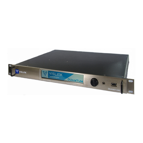
Vislink airstream LGR-1000 User manual

Live Gear Receiver
LGR-1000
User and Technical Manual
Manual Part No. RD000785 Rev. C, March, 2014

Page 2
LGR User Guide and Technical Manual
Copyright © 2014
Part number RD000785
Printed in U.S.A.
Authorized EU representative: Vislink PLC
Quality Certification Vislink is certified to ISO 9001:2008.
The Vislink trademark and other trademarks are registered trademarks in the United States and/or other countries.
Microsoft®, Windows®, and Internet Explorer® are registered trademarks of Microsoft Corporation in the United
States and/or other countries.
Proprietary Material The information and design contained within this manual was originated by and is the
property of Vislink. Vislink reserves all patent proprietary design, manufacturing, reproduction use, and sales rights
thereto, and to any articles disclosed therein, except to the extent rights are expressly granted to others. The
foregoing does not apply to vendor proprietary parts. Vislink has made every effort to ensure the accuracy of the
material contained in this manual at the time of printing. As specifications, equipment, and this manual are subject
to change without notice, Vislink assumes no responsibility or liability whatsoever for any errors or inaccuracies that
may appear in this manual or for any decisions based on its use. This manual is supplied for information purposes
only and should not be construed as a commitment by Vislink. The information in this manual remains the property
of Vislink and may not be used, disclosed, or reproduced in any form whatsoever, without the prior written consent of
Vislink. Vislink reserves the right to make changes to equipment and specifications of the product described in this
manual at any time without notice and without obligation to notify any person of such changes.
General Safety Information The following safety requirements, as well as local site requirements and regulations,
must be observed by personnel operating and maintaining the equipment covered by this manual to ensure
awareness of potential hazards. This equipment has been tested and found to comply with the limits for a Class
A digital device, pursuant to Part 15 of the FCC Rules. These limits are designed to provide reasonable protection
against harmful interference when the equipment is operated in a commercial environment. This equipment
generates, uses, and can radiate radio frequency energy. If not installed and used in accordance with the instruction
manual, it may cause harmful interference to radio communications. Operation of this equipment in a residential
area is likely to cause harmful interference in which case the user will be required to correct the interference at his
own expense.
1) The Live Gear Receiver complies with Part 15 of the FCC Rules. Operation is subject to the condition that this
device does not cause harmful interference.
About this Manual This manual is intended for use by qualified operators, installers, and service personnel. Users
of this manual should already be familiar with basic concepts of radio, networking, video, and audio. For information
about terms in this manual, see Glossary of Terms and Abbreviations Part No. 400576-1). Pay special attention to
Notes, Cautions, and Warnings.
§Read NOTES for important information to assist you in using and maintaining the equipment
§Follow CAUTIONS to prevent damage to the equipment.
§Follow WARNINGS to prevent personal injury or death.

Page 3
LGR User Guide and Technical Manual
Table of Contents
Unpacking the LiveGear Receiver ....................................................4
Introduction........................................................................................5
Features...............................................................................................................6
LGR Operation ..................................................................................7
LGR and AirStream System Setup....................................................8
Initial Setup ..........................................................................................................8
Configuration Steps to Stream Video ..................................................................8
LGR Login Web Page......................................................................10
LGR Status Web Page ....................................................................11
Current Status ...................................................................................................12
Interface Details ................................................................................................12
LGR IFB Settings...............................................................................................13
Local Channel Setup .........................................................................................13
IFB Call ..............................................................................................................13
LGR Network Settings Web Page...................................................14
WAN and LAN Configuration.............................................................................14
WAN Configuration ............................................................................................15
LAN Configuration .............................................................................................15
LGR Decoder Settings Web Page...................................................16
Channel -1 & 2 Output.......................................................................................16
LGR Inputs Web Page.....................................................................17
LGR Inputs.........................................................................................................17
LGR Outputs....................................................................................19
LGR Support, System and Software Upgrade Web Page..............21
LGR System Information ...................................................................................21
LGR Support Information...................................................................................21
LGR Software Upgrade .....................................................................................21
Upgrade Software..............................................................................................21
Specifications...................................................................................23
Video..................................................................................................................23
Audio..................................................................................................................23
Controls/Displays...............................................................................................23
Physical..............................................................................................................23
Environmental....................................................................................................23
Appendix A: LGR Connectors & Controls .................................... 24
Glossary...........................................................................................25
Notes..................................................................................................................27
Support for Your Vislink Product......................................................28

Page 4
LGR User Guide and Technical Manual
Safety Instructions
• Always use the correct power source during operation to avoid damaging the
product.
• Rough handling of the product may cause physical damage or malfunction.
• It is not recommended to use the product in harsh weather conditions or very low or
high temperatures.
• To ensure that the warranty remains valid, please do not disassemble the unit.
Unpacking the LiveGear Receiver
Before you install your new equipment, carefully unpack your equipment to avoid acci-
dental damage.
• Locate all parts and accessories and verify that they are listed on the packing list.
DO NOT discard the container or packing material until you have inspected the
equipment and are sure there is no shipping damage. The container and pack-
ing must be available in case you need to file a damage claim with the shipping
carrier.
• Inspect the equipment for damage and that it is clean and dry.
• Inspect the cables, connectors, switches, and displays to ensure that they are not
broken, damaged or loose.
If you discover damage after unpacking the system, report the damage as follows:
• Immediately file a claim with the shipping carrier.
• Forward a copy of the damage report to Vislink Customer Service.
• Contact Vislink Customer Service to determine the disposition of the equipment.
See: Support for Your Vislink Product on the last page.

Page 5
LGR User Guide and Technical Manual
Introduction
The LiveGear Receiver [LGR-1000] is a cellular Internet News Gathering [iNG]
Receiver and an integral part of the AirStream transmitter systems. The LiveGear
Receiver is a playout device that receives IP transmissions via the Internet and provides
a HD/SD-SDI output. Up to six transmitters [future option] can be simultaneously
received using one LGR receiver. The LGR-1000 is an effective means to receive “live”
remote iNG content and only requires an Internet connection. The AirStream transmitter
- LGR setup is accomplished using the AirStream Web interface. The LGR can also be
configured using the LGR Web pages.
The LiveGear receiver is typically installed at a broadcast studio or technical operations
center. Up to six bonded cellular network IP streams carrying a packetized segment
of the video transmission are received from each remote AirStream transmitters.
The bonded IP packets are aggregated to produce a single reconstructed IP stream
containing the original AirStream HD video transmission.
The IP transport stream is decoded to HD/SD-SDI and can be passed through as IP
to the studio server for distribution to customer edge devices such as smartphones,
tablets, laptops or PCs. A second licensable LiveGear IP-to-SDI decoder output is
available in the standard configuration. A four-output expansion card [each output
licensable] is available as a factory upgrade to support a total of 6 SDI outputs. Up to
five additional video transport streams can be enabled in the LGR-1000 receiver to
decode simultaneous HD/SD-SDI outputs.
The receiver also provides a duplex Interruptible Foldback [IFB] channel for monitoring
and operator cueing of remote transmitters. System configuration of the receiver and
transmitter is controlled by an integrated Web browser GUI interface.

Page 6
LGR User Guide and Technical Manual
Features
§Live Gear Receiver [LGR-1000] – Compact, powerful performance in a two RU
19” rack mount unit.
§Plug-n-Play – Connect the LGR-1000 to an Ethernet ISP connection and
instantly decode your remote transmitters.
§Reception Integrity – Exclusive Vislink algorithms optimize IP cellular
transmission.
§Video Quality – Dependable forward error correction [FEC] algorithms ensure
seamless decoding of the H.264 video signal.
§Video Output – HD/SD-SDI
§Audio – Embedded Stereo in MPEG 2 or AAC-LC
§Reliability – Using wireless 3G/4G cellular, Wi-Fi/WiMAX, or BGAN satellite
backhaul communication infrastructures, the LGR delivers video/audio signals
when and where you want them.
§Low or No Capital Expense – Whether you decide to purchase or lease,
the LGR is an affordable video reception solution at a fraction of the cost of
traditional content gathering microwave systems.
§Versatility – The LGR-1000 can receive up to six incoming HD/SD-SDI
AirStream transmitters converting the Ethernet IP data into individual HD/SD-
SDI outputs.
§Access – The VMS-1100 base system transcodes and streams out to multiple-
edged viewing devices such as smartphones, tablets, or laptop computers.
§Playout – The LiveGear Video Media Server connects multiple transmitters to
your website.
§Configuration Options – Use a PC, laptop, tablet, smartphone or any device with
an Internet connection to configure the LGR from its Web pages.

Page 7
LGR User Guide and Technical Manual
LGR Operation
The LiveGear Receiver features a front panel User Interface - an alphanumeric LCD
menu-driven display as well as a convenient Web interface, putting the intuitive control
of this device at your fingertips using a pc, tablet, laptop or smart phone. Refer to the
figures below for the LGR front and rear connections and controls.
Power Switch
Local Area Network
Ethernet Port Front Panel UI Controls
IFB I/O Plugs AC Power Cable Input &
Power Supply Switch
Local Area Network Ethernet Ports
Wide Area Network Ethernet Port
SD/HD SDI Out Coaxial
Connections
GEN 1 = GEN LOCK IN
1 & 2 = SD/HD SDI OUT
Debugging Connections
[for factory use only]
Front Panel Liquid Crystal Display [LCD]
Install the WAN, LAN and Coaxial connections. After installing the AC power cord,
set the power supply switch to 1 and press the Power switch on the LGR face plate to
display the LCD panel. The front panel LCD UI provides a means to view the basic LGR
settings that can be controlled via the LGR Web interface [refer to page 12].
Refer to
Appendix A: LGR
Connectors & Controls
for more information.

Page 8
LGR User Guide and Technical Manual
LGR and AirStream System Setup
This section describes how to configure an AirStream/LiveGear Receiver pair and begin
streaming video over a cellular network as quickly as possible using the default settings.
After receiving an AirStream and LGR, the first device to be configured should be the
LGR. This process consists of setting the WAN IP address of the LGR and depending
on your network setup, potentially setting up port forwarding. After configuring the LGR,
the AirStream can be setup to stream to your configured LGR. Consult the AirStream
User Guide and Technical Manual for more information about the transmitter-receiver
interface.
Initial Setup
It is recommended that you preconfigure the transmitter and receiver together in the
studio, to ensure that the initial settings are analogous . It is also suggested that you
test the system with a live video feed prior to sending a transmitter team to a remote
location. The initial steps for the configuration procedure are as follows:
Live Gear Receiver [LGR-1000]- Refer to the figure above.
Connect AC Power Supply.
Connect Video Output [SD/HD OUT / 1 to monitor].
Connect Ethernet Cable [WAN port to router].
Set the rear Power Supply switch to On position.
AirStream Transmitter
Install SIM cards [up to 6]
Install external antennas [Wi-Fi or International Configuration].
Connect video source [on left side of transmitter].
Connect power supply [battery or DC adapter].
Configuration Steps to Stream Video:
1. Connect a laptop to the four port switch on the rear panel and apply power to the
LGR by setting the Power Supply rocker switch on the rear panel and by pressing
the front panel Power push button. Check the LCD to ensure that the
initialization process has completed.
2. Browse to the default IP address of the LGR on the LAN at http://192.168.2.200.
Log in using the UID/PW: admin/admin.
3. Browse to Setup > Network Settings
4. Set your IP address information in the WAN Configuration box and click Save.
NOTE: If you are placing the LGR behind a router/firewall, you will need to
forward at a minimum, port 4001 TCP/UDP to the LGR. You can change the
LGR’s listening port on the Setup > LGR Inputs page. If you do change the port,
be sure to change the port on the AirStream as well.

Page 9
LGR User Guide and Technical Manual
Configuration Steps [continued]
5. On the LiveGear Receiver:
a. Using the LCD on the front panel, press the up arrow to display the WAN
IP address. This IP address needs to be entered in the host address field using
the AirStream touchscreen or Web page.
b. Default Listening Ports are: 4001 for Channel1 or 4002 for Channel.2.
c. Save the settings
d. Select the Status button to return to the Status screen.
6. Apply power to the AirStream using power rocker switch on left side. Wait for the
initialization process to complete [approximately 3 minutes]. Ensure that you have
installed fully-charged batteries [or use DC input]. Batteries must be recharged
using an external charger. Allow approximately six minutes for the AirStream to
boot up and optimize the cellular links for broadcast.
a. After approximately 30 seconds, a green screen appears.
b. After approximately 30 more seconds, the green screen disappears.
c. Once 3-6 minutes have elapsed, the Status Touchscreen appears.
7. On the AirStream transmitter:
a. Check that the Cellular Status screen shows service for the cell modems with
SIM cards installed. Reboot the transmitter if the cellular carriers do not connect.
b. Adjust the Cell Mode [Delay] desired for transmission on the Status
Touchscreen.
c. Once the AirStream is booted and the modems are connected, press
Setup>Video/Audio Settings to begin configuration.
d. Adjust the Encoder Bitrate Control based on the carrier service available.
e. Select the Video/Audio Option and choose the correct Video Input Resolution,
Audio Mode and Encoding Mode.
f. Be sure that the Stream Output is set to Modem for cellular transmission or
wired for Ethernet transmission and press the Save button.
g. Select Back to return to the Setup Menu.
h. Select LGR and set the Host address to the IP address of the configured LGR,
then press the Save button.
NOTE: If you setup a different port number on the LGR, you can change the Port
number on the LGR Touchscreen to match that selected for the receiver.
i. Ensure that you have a secure connection to your video source at the Video
Input BNC connector on the left side of the AirStream transmitter.
j. Select the AirStream’s Start On Air button to begin live streaming.
NOTE: Disconnect video and wait five seconds before reconnecting when changing
resolutions.
8. You can view connection status by logging into the LGR Web interface and
selecting Channel 1 on the dropdown.

Page 10
LGR User Guide and Technical Manual
LGR Login Web Page
Type the LGR IP address in a Web browser to display the Login Web page. The default
user ID and password is admin. This page also appears when you select the Logout
tab in any of the Web pages, allowing you to reenter your user name and password or
login a new user. Refer to the sample Web page shown below.

Page 11
LGR User Guide and Technical Manual
LGR Status Web Page
The LGR Status page displays first when you open the LGR Web interface. There are
three sections of the Status page: Current Status, Interface Details and IFB Settings.

Page 12
LGR User Guide and Technical Manual
You can also access the Status page when you click the logo in either
the LGR [or AirStream] Web pages. The LGR Web pages can be accessed from a
PC or laptop connected to a LAN port on the LGR-1000. The default IP address is
http://192.168.2.200/. You can also address a static IP on a PC within that network
range [for example: http://192.168.2.50/]. The default user ID and password is admin.
You can also set the WAN IP to DHCP and click Save Changes, to access a WAN IP
address by which you may route the AirStream transmissions. Refer below to the LGR
Network Settings Web Page section.
Mouse-over help is also available throughout the Web pages.
Current Status
Select a Channel to Monitor
Use the drop-down to select a channel from 1 to 6.
Incoming Throughput
This graphic displays the bit rate of the incoming video feed from the individual cellular
carriers for the selected channel. The combined throughput is also displayed.
RTT [Round Trip Time]
This graphic displays the Round Trip Time for the signal from the transmitter to the
LiveGear Receiver.
Utilization Rate
This graphic displays the rate that the bandwidth is used to transmit the signal.
Interface Details
The Interface Details table includes the following data:
• Interface
• Carrier
• Service
• RSSI
• SNR
• SIMID
• Status

Page 13
LGR User Guide and Technical Manual
LGR IFB Settings
The IFB setup for the LGR include the channel being listened to and the IFB call state
fields, as shown in the sample Web page above.
Local Channel Setup
Select Channel
Select an open Channel from which the LGR will receive the IFB signal. The channels
dedicated to IFB reception range from 1 to 6. These channels represent ports 5061 to
5066. Be aware of this when performing any port-forwarding through firewalls.
IIFB Call
IFB Call Connections
When you click Answer, the IFB feed will be activated on the channel that you have
selected from the IP address indicated. Click Hangup to terminate the IFB session.
The IFB call is initiated at the AirStream transmitter. Refer to the AirStream User
Guide and Technical Manual for more information concerning the use of this feature.

Page 14
LGR User Guide and Technical Manual
LGR Network Settings Web Page
The LGR’s network setup page includes entry fields for Wide and Local Area Networks,
as shown below.
WAN and LAN Configuration
The Wide and Local Area Network configuration entry fields include: IP Type and
Address [if required], Net Mask, Gateway and DNS Server. For DHCP server
configurations, LAN Start Address and Maximum Clients are displayed. The LAN
settings are used for troubleshooting and configuration purposes. The Wide Area
Network receives the video broadcast from the AirStream transmitter.

Page 15
LGR User Guide and Technical Manual
WAN Configuration
IP Type
The Internet Protocol Type drop-down entry field provides the choice of either Static or
DHCP [Dynamic Host Configuration Protocol] to configure the LiveGear receiver. Set your
own IP address by selection of Static IP Type or change to DHCP to set the address from
your DHCP server.
IP Address
The Internet Protocol Address that is used by the LiveGear receiver can be modified using
the IP Address entry field. Click within the field and type the value of the address that you
want to modify. Click Save to retain the IP Address.
Net Mask
A sub-network, or subnet, is a logically visible subdivision of an IP Network.
To change the LGR Local Subnet address, click within the address field and type the
value of the address that you want to modify. Modify the Subnet address to match settings
provided by your network administrator. Click Save to retain the Subnet Mask Address.
Gateway
The Gateway address, or Default Gateway, is a router interface connected to the Local
or Wide Area Network [LAN or WAN] used to send packets from the LAN. The Gateway
Address that is displayed for the LGR can be modified. Click within the address field
and type the value of the address that you want to modify or enter. Modify the Gateway
address to match settings provided by your network administrator. Click the Save tab to
retain the IP Address.
DNS Server
The DNS IP Address that is displayed for the LGR can be modified. Click within the field
and type the DNS address. Modify the DNS IP address to match settings provided by
your network administrator. Click Save to retain the IP Address.
LAN Configuration
For information regarding IP Address, Net Mask, Gateway and DNS, see the explanations
listed above.
IP Type
The Internet Protocol Type drop-down entry field provides the choice of
• Static
• DHCP [Dynamic Host Configuration Protocol] Client or
• DHCP Server
to configure the LiveGear receiver. Set your own IP address by selection of Static IP Type
or change to DHCP to set the address from your DHCP server.

Page 16
LGR User Guide and Technical Manual
Start Address
This field sets the starting IP address range when the IP type is set to DHCP server
mode.
Maximum Clients
This entry field allows the selection of the maximum number of clients permitted when
the DHCP server is used. The maximum entry is 50.
Save Changes
Be sure to click the Save Changes button to retain revisions to the Network Settings
page.
LGR Decoder Settings Web Page
The LGR Decoder setup includes MPEG Transport Stream and Output settings
including Genlock, Resolution, Caching and Port number.

Page 17
LGR User Guide and Technical Manual
Decoder Resolution
The Video Decoder Resolution drop-down field allows the selection of the following:
• 480i [NTSC]
• 576i [PAL]
• 720p60
• 720p59
• 720p50
• 1080i60
• 1080i59
• 1080i50
• 1080p23
• 1080p24
• 1080p25
• 1080p29
• 1080p30
Caching
This entry field allows you to set caching for the MPEG Transport Stream. The valid
range is between 70 to 1000 ms. The default value is 300 ms.
Save Changes
Click Save Changes to retain your selections of LGR Outputs.
LGR Inputs Web Page
LiveGear Receiver Inputs are ports where an LGR listens for incoming connections.
LGR Inputs
Channel
This field displays the LiveGear Receiver’s Channel.
Status
This check box displays the LiveGear Receiver’s Input Status. Click within the check
box to enable the Input Channel.
Port Number
The LiveGear Receiver’s input Port is selected and displayed in this field. Valid ports
include any unused within the range of 1 through 65535.

Page 18
LGR User Guide and Technical Manual
Save Changes
Click Save Changes to retain your selections of LGR Inputs.

Page 19
LGR User Guide and Technical Manual
LGR Outputs
LGR Outputs Web page includes LiveGear Receiver Output Information. Refer to the
sample Web page shown below.
LGR Outputs
Enabled
Click the Enabled check box to allow the output to be used.
Name
This field displays the output name.
Input Stream
This field displays the channel from which the transmitter’s signal is streaming to the
LGR.
Stream Output
This field displays the LGR Output Port.

Page 20
LGR User Guide and Technical Manual
Receiver IP
The receiver’s IP Address is displayed in this field.
Port #
The output port number is displayed in this field.
The add output button allows you to create a new output for the LGR using the New
Output dialog box shown below. Click Save to retain your output configuration.
The edit output button allows you to revise a previously created LGR output using the
dialog box shown below. Click Save to retain your revised output configuration.
The delete output button removes an output.
The refresh button allows you to display the changes that you have made for an
existing output or add a newly created LGR output, after you have clicked Save in the
dialog box shown below.
Table of contents
Other Vislink Receiver manuals
Vislink
Vislink RCD9 User manual
Vislink
Vislink Lynx L2174 User manual
Vislink
Vislink Strata RX Product manual

Vislink
Vislink HDR-5000 User manual
Vislink
Vislink HDR-1000 User manual
Vislink
Vislink Live Gear NewStream User manual
Vislink
Vislink HHT3 User manual

Vislink
Vislink Lynx L2174 User manual
Vislink
Vislink UltraReceiver User manual
Vislink
Vislink UltraReceiver LD User manual
