SignalFire GWS-CBBL User manual
Rev 4.9 SignalFire Telemetry
1
Interface Manual
Gateway-In-A-Stick
SignalFire Number: GWS-CBBL
The SignalFire Gateway-In-A-Stick has the following features:
-RS485 connection to Modbus client device (Optional Modbus-TCP interface module)
-Wide range DC power input: 6-36VDC
-Collects and caches Modbus data from all SignalFire remote devices
-Provides configuration and status registers for remote configuration and status monitoring
-Integrated 500mW FHSS 900MHz ISM band radio and high gain antenna
-Stores up to 4700 register values from any combination of remote nodes
-Supports transparent Modbus mode
-Internal Remote Shut Down (RSD) logic control option
-Modbus register re-mapping
-Remote configuration of SignalFire devices through an Ethernet gateway connection
-Remote sensor configuration (PACTware and RadarMaster)
-AES-128 Encryption
-Class 1 Division 2 Area certification

Rev 4.9 SignalFire Telemetry
2
Table of Contents
Specifications _______________________________________________________________________________________ 4
Connections and Components _____________________________________________________________________ 5
Gateway-In-A-Stick Connections_________________________________________________________________ 5
Status LED ________________________________________________________________________________________ 5
Operation _________________________________________________________________________________________________________ 6
Remote Modbus Sticks and Sentinel-Modbus (non-sleeping radio only) Nodes ______________________________ 6
Remote Modbus Stick Node Re-Scan __________________________________________________________________________ 6
Setup _____________________________________________________________________________________________________________ 7
Optional Ethernet Gateway Connections_______________________________________________________________________ 7
Encryption ______________________________________________________________________________________________________ 9
Checking Remote Nodes ________________________________________________________________________________________ 10
Remote Node Configuration __________________________________________________________________________________ 11
Firmware Upgrades ______________________________________________________________________________________________ 13
Rescue Gateway (ARM) Bootload _____________________________________________________________________________ 13
Remote Shutdown (RSD) Control________________________________________________________________________________ 14
RSD Configuration ____________________________________________________________________________________________ 15
Source Value Section __________________________________________________________________________________________ 15
Relay Control Logic Section ___________________________________________________________________________________ 16
Destination RSD Stick Section _________________________________________________________________________________ 17
Relay Pulse ____________________________________________________________________________________________________ 17
Example _______________________________________________________________________________________________________ 18
RSD Event log _________________________________________________________________________________________________ 18
Additional Options ____________________________________________________________________________________________ 19
Output Modules _________________________________________________________________________________________________ 19
Modbus Register Remapping____________________________________________________________________________________ 20
Use Data Type Floats __________________________________________________________________________________________ 21
Fail Mode______________________________________________________________________________________________________ 22
Load/Save Files________________________________________________________________________________________________ 22
Import/Export CSV Files _______________________________________________________________________________________ 22
RS485 Details ____________________________________________________________________________________________________ 23
Network Map ____________________________________________________________________________________________________ 23
Gateway Event Log ______________________________________________________________________________________________ 24
Saving the Gateway Log_______________________________________________________________________________________ 24

Rev 4.9 SignalFire Telemetry
3
Modbus Gateway Register Map ___________________________________________________________________ 25
Coils _____________________________________________________________________________________________ 25
Holding Registers _______________________________________________________________________________ 26
Revision History____________________________________________________________________________________ 30
Hazardous Location Certification __________________________________________________________________ 31

Rev 4.9 SignalFire Telemetry
4
Specifications
Gateway Size
Mounting
20.5” overall length. 1.45” diameter
¾” Female NPT fitting
Power Source
6-36VDC. 25mA @ 12VDC (average), 17mA @ 24VDC (average)
Temperature Rating
-40°C to +85°C
Radio
902-928MHz ISM Band, FHSS radio. IC and FCC Part 15 certified
Integrated 5dBi antenna. FCC ID: W8V-M655, IC: 8373A-M655
Compliance
Certified for use in Class I, Division 2 groups C and D. Certified to CSA
C22.2-2015 No. 142, CSA22.2 No. 312213, ISA 12.12.01-2015 and UL916
s

Rev 4.9 SignalFire Telemetry
5
Connections and Components
Gateway-In-A-Stick Connections
The Gateway-In-A-Stick is supplied with a 6’ conductor cable. The connections are as follows:
Wire Color
Connection
RED
Positive Power (6 to 36 VDC)
BLACK
Ground
GREEN
RS-485 “A”, 9600 Baud
BROWN
RS-485 “B”, 9600 Baud
ORANGE
RS-232 Debug/Programming TX, 9600 Baud
YELLOW
RS-232 Debug/Programming RX, 9600 Baud
Status LED
The Gateway has one LED Available for field diagnostics.
LED
Description
Slow Flash (3 second pause)
System is running and in communication with radio network
Fast Flash (0.5 second pause)
System is running but no network found
Solid On
System Fault needs service or rescue bootload

Rev 4.9 SignalFire Telemetry
6
Operation
The Gateway-In-A-Stick supports all remote SignalFire nodes making all remote sensor data
available in Modbus format.
The register data from remote sensor nodes is available by requesting the remote node’s Modbus
ID and register address from that node’s register map. The gateway will respond with the most recent copy of
the data from the remote node. The gateway will automatically time-out data from a remote node it stops
receiving data for.
If the remote node is a Modbus-Stick interface node additional features are supported.
Remote Modbus Sticks and Sentinel-Modbus (non-sleeping radio only) Nodes
Remote nodes that have been pre-configured forward their set of registers to the Modbus gateway on a pre-
defined schedule (1 minute to 5 minutes is typical). The register data is then buffered in the gateway and is
available to be read by the RTU at any time.
If a Modbus request is received by the gateway for a Modbus ID and address for which buffered data does not
exist, but the Modbus ID is known, the Modbus request will be forwarded to the remote Modbus node over the
SignalFire network. The response is returned to the RTU.
If a request for multiple registers is issued by the RTU, and if the gateway does not have all registered data
buffered, an exception will be returned. The system will not combine buffered and transparent data within a
single Modbus response.
Remote Modbus Stick Node Re-Scan
It is possible to cause a remote Modbus Stick to re-scan for attached Modbus devices by writing to one of the
gateway’s configuration registers. This is useful to discover a Modbus device that is added to an existing
Modbus node. The scan may be initiated by one of the two methods. First, if the radio address of the Modbus
Stick is known, writing this address to gateway register 3000 will result in a scan. Second, if the Modbus ID of
one of the already registered devices attached to a Modbus Stick is known, a scan will be started by writing the
ID to gateway register 3002.
Rev 4.9 SignalFire Telemetry
7
Setup
The Gateway-in-a-Stick requires an initial configuration over RS-232 using the SignalFire Toolkit.
Connect a USB-Serial cable (can be purchased from SignalFire) between a computer and the
Gateway’s DB9 port.
The following items must be configured to set up a SignalFire network:
-Radio Network
-Radio Network Group
-Corporate ID/Encryption Key
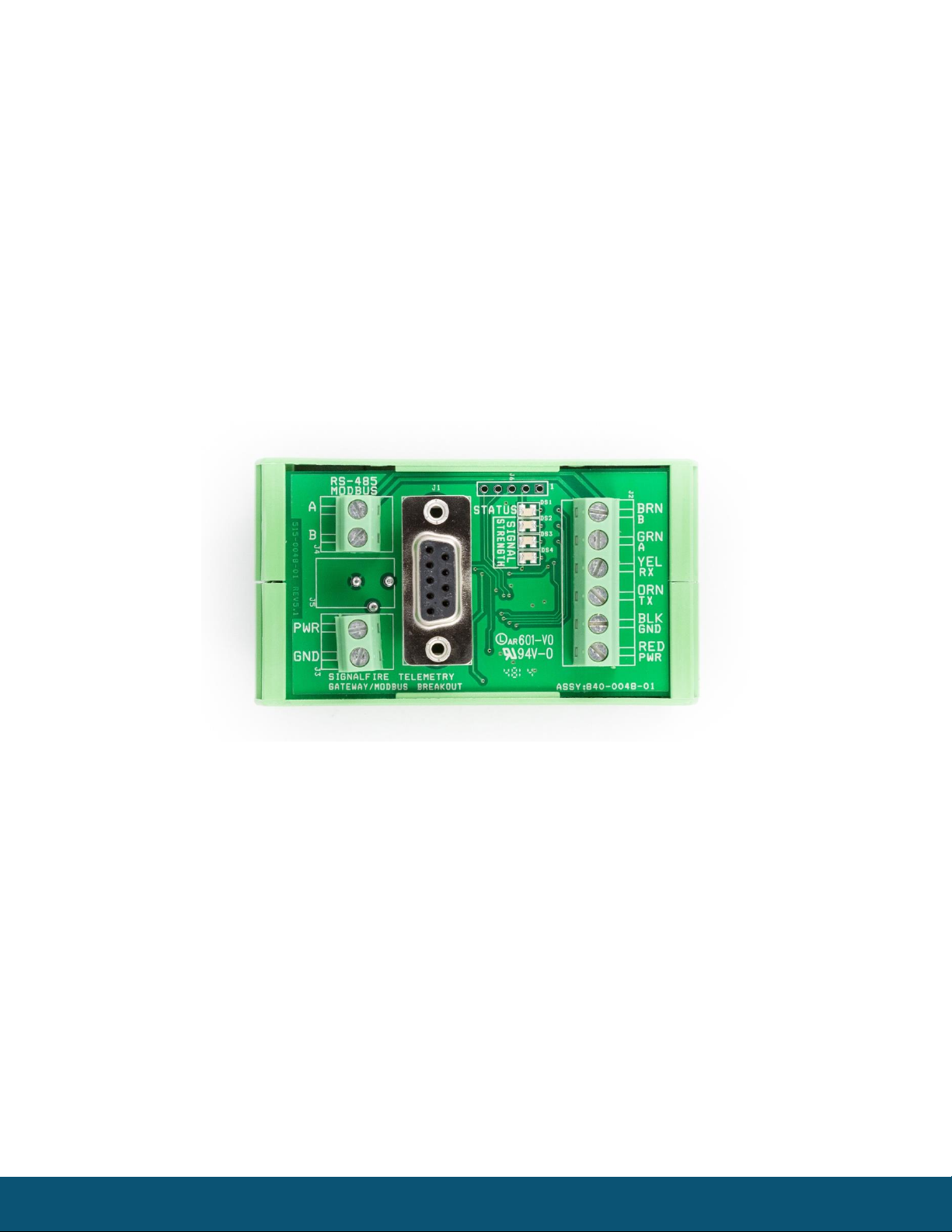
The standard SignalFire Connector-Breakout-Board (CBB), pictured below, provides an easy means to connect
to the RS232 lines and power the device while configuring the system. Note that the signal strength LEDs do
not light at the gateway as multiple nodes with varying signal strength may be connected at one time.
Optional Ethernet Gateway Connections
When used with a SignalFire Ethernet Interface Module, the 6 wires should be connected to the color coded
“Gateway Stick Connection” connector on the Ethernet Interface Module. Power can be supplied either to the
Power Input terminals on the Ethernet Interface Module or via power over Ethernet (PoE). For more information
on configuring and using the Ethernet Interface Module, please consult the Ethernet Interface Module manual.
Rev 4.9 SignalFire Telemetry
8
Using the SignalFire Toolkit
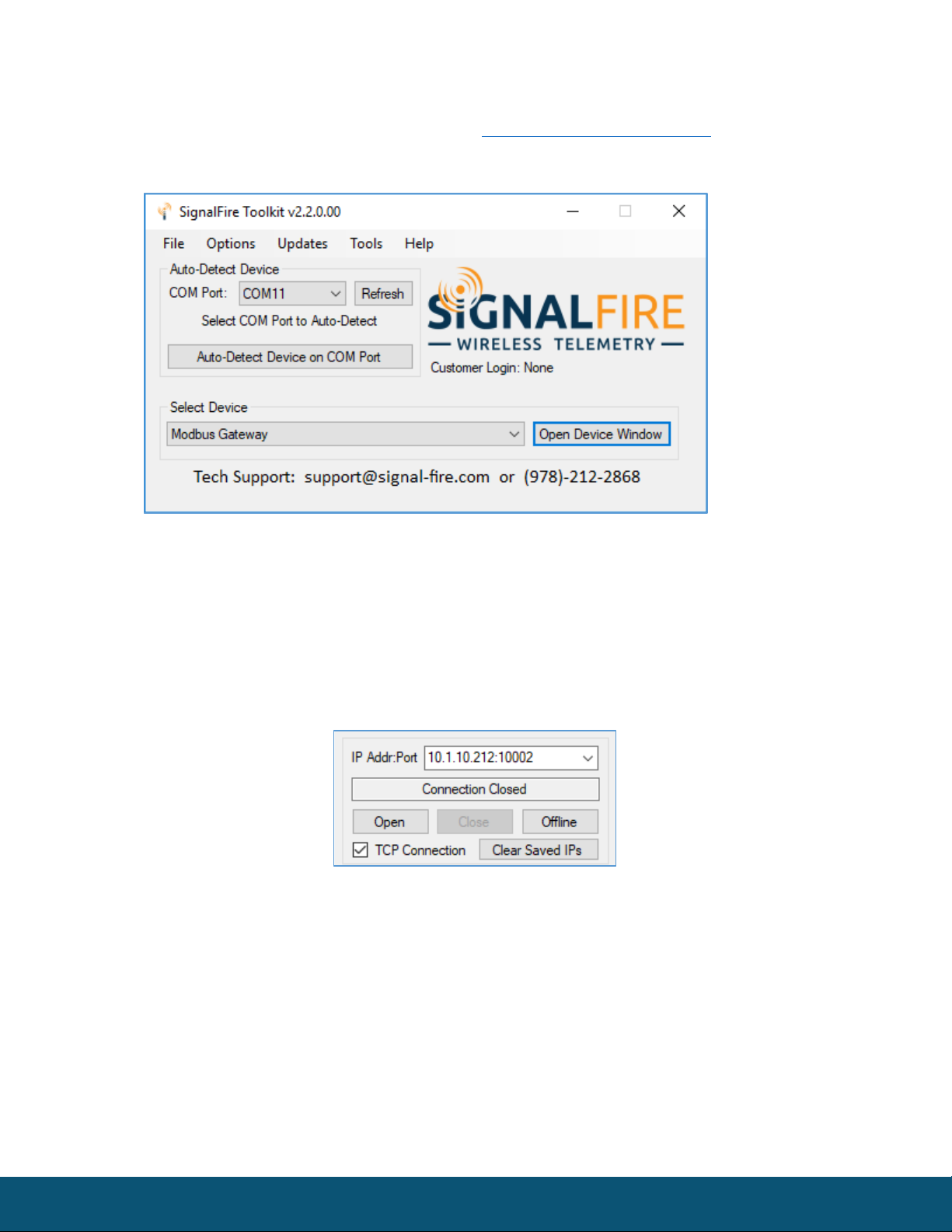
The SignalFire Toolkit application can be downloaded at www.signal-fire.com/customer. After
installation, launch the software and the main toolkit window will open:
Select the COM port associated with the Gateway Stick and click “Auto-Detect Device on COM Port.” This will
open the device configuration window, where all device settings can be configured.
If the Gateway is connected to an Ethernet Module, instead select the Modbus Gateway Stick in the dropdown
menu of the main ToolKit window, and click “Open Device Window”. In the upper left corner, check off the “TCP
Connection” box, type in the IP Address, and click “Open”. The port number (10002) will be automatically
added, so this is not necessary to enter it.

Rev 4.9 SignalFire Telemetry
9
Network Setting
The network is set using the SignalFire Toolkit. There can only be one Gateway per
network/group/encryption combination, otherwise they will conflict. In a system with multiple
Gateways, each Gateway must be on a separate network/group/encryption combination. The
network, network group, and corporate ID/encryption key settings must match those of its
nodes for them to communicate.
Encryption
To protect your over-the-air data and prevent tampering, SignalFire networks starting with radio version 2.50
and Gateway version 7.93 come with encryption. Legacy products use a Corporate ID, but can be switched over
to use an encryption key if the firmware and ToolKit are up to date.
To set up a legacy Gateway to use encryption, click the checkbox labeled Enable Encryption inside the Set
Corporate ID box. All Gateways now default with this option enabled and “signalfire” as the default encryption
key.
Radio settings box with and without encryption enabled. For more details, click the Help button.
The box will then change into a Set Encryption Key box, and it will prompt instead for the encryption key you
would like to use. Note that keys may not contain spaces or angle brackets. Enter it and then press Set. If you are
setting up a new network, you will need to set the encryption key on all of your devices. If you are swapping out
the Gateway for a legacy network, you can simply uncheck Enable Encryption and set the Corporate ID, and it
will remain compatible with the older system.
It is also possible to hide your encryption key so it cannot be read. This is the most secure option, but if you
forget your key, there is no way to recover it – you must reset the key on every device on its network. To enable
this option, select Set Encryption Key Unrecoverable under the Settings menu.

Rev 4.9 SignalFire Telemetry
10
Checking Remote Nodes
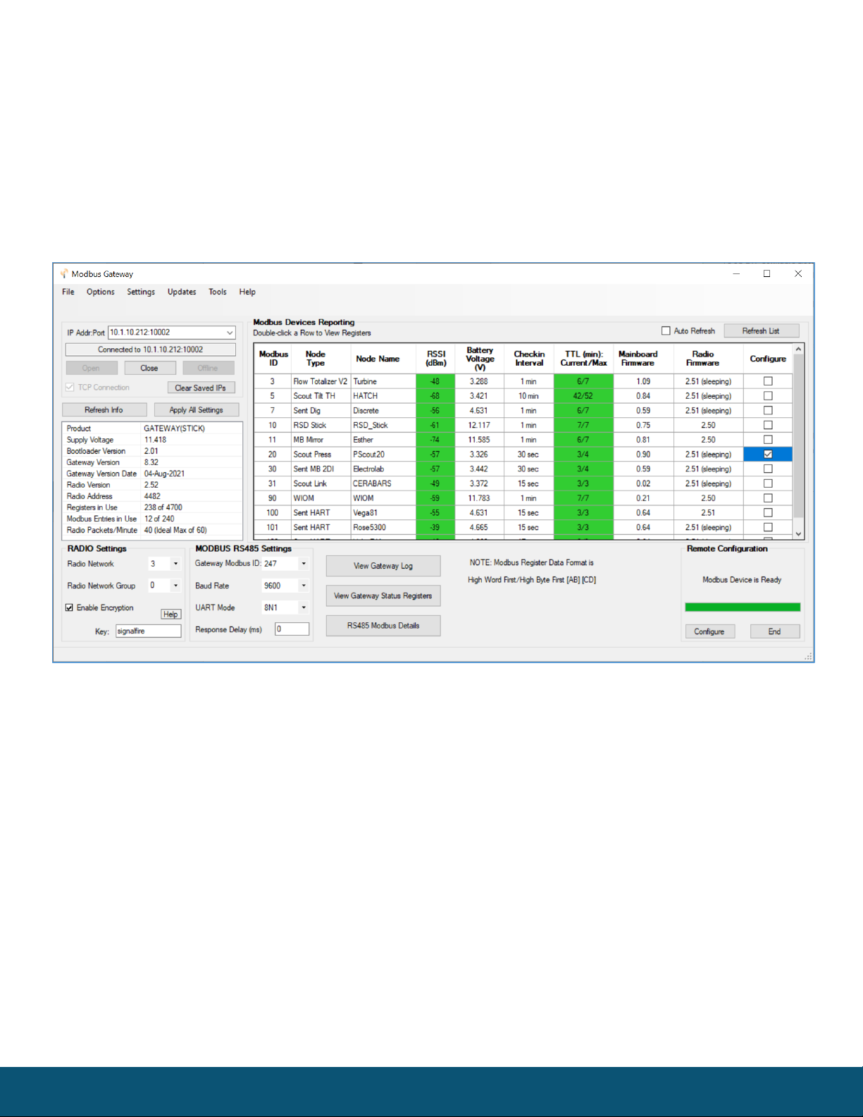
If one or more remote nodes are configured with the correct network settings, they will send their
data to the gateway. Clicking Refresh List will populate the list with all connected remote nodes.
The gateway displays the node type, node name (if it has been set), RSSI signal strength, check-in
interval, the Time-To-Live (TTL), and the node’s radio and main firmware versions.
The RSSI and TTL values are color coded (Green, yellow, orange, red) to indicate relative link quality of a node.
The ‘TTL Current’ indicates the number of minutes remaining until the node will be timed out of the gateway if
no updates are received. The ‘TTL Max’ indicates the maximum TTL for that node and is equal to the node’s
check-in interval times 5 plus 2. The ‘TTL Current’ will reset to the ‘TTL Max’ each time an update is received
from that node. The ‘TTL Current’ will decrement once a minute.
Double clicking on one of the nodes in the list will bring up additional detail including the register data from
the remote node.
Rev 4.9 SignalFire Telemetry
11
Remote Node Configuration
The SignalFire Gateway allows configuration changes to be made to any of the connected
SignalFire remote nodes wirelessly. To use this feature, access to the Gateway debug port is
required. This may be accessed over a TCP/IP network using a SignalFire Ethernet Gateway
module, or by a direct connection to the Gateway RS232 port.
To start a remote configuration session with a remote node, select the check-box next to the node to configure.
If the device has a non-sleeping radio the remote configuration session will be ready immediately. If it is a
sleeping device, you must wait for the node to either check-in or send a “beacon” so that it can be
commanded to enter configuration mode. The Sentinel/Scout nodes send a beacon every two and a half
minutes, while all other sleeping nodes send a beacon every five and a half minutes. When the device has
entered a remote configuration session you will see a message indicating the device is ready. Click Configure
to open the configuration window (image on next page).

Rev 4.9 SignalFire Telemetry
12
Make any necessary changes and click the Apply All Settings button to save the changes. When
finished with the configuration, close the configuration window and then click the End button in
the Gateway window to end the session. The session will also automatically time-out after 15
minutes of inactivity and the Node will resume normal operation.
Example Remote Configuration Window
Further information on how to remotely configure a HART device through the ToolKit using PACTware can be
found in the “Remote HART Sensor Configuration Manual”.

Rev 4.9 SignalFire Telemetry
13
Firmware Upgrades
Firmware updates for both the gateway (ARM) and the built-in radio are possible over the
RS-232 debug interface using the SignalFire Toolkit, or over a remote TCP connection if an
Ethernet Gateway module is used.
Gateway (ARM) Firmware update steps
1Open the SignalFire Toolkit application.
2Open the correct COM port connected to the RS-232 port of the gateway.
3Go to the Update menu and select Update Gateway Firmware.
4The latest gateway firmware file will be selected by default.
5Click Start Upgrade.
Gateway Radio Firmware update steps:
1Open the SignalFire Toolkit application.
2Open the correct COM port connected to the RS-232 port of the gateway.
3Go to the Update menu and select Update Radio Firmware.
4The latest radio firmware file will be selected by default.
5Click Start Upgrade.
Rescue Gateway (ARM) Bootload
If in the process of a firmware update there is a power failure or other communications failure it may be
necessary to do a “rescue bootload.” If the base LED is solid on and/or the Toolkit is unable to communicate
with the Gateway the following process is necessary.
1Remove DC power to the Gateway.
2Open the SignalFire Toolkit application.
3Open the correct COM port connected to the RS-232 port of the gateway.
4Go to the Update menu and select Update Gateway Firmware.
5The latest gateway firmware file will be selectable by default.
6Click Start Upgrade.
7Now re-connect the DC power to the gateway. The firmware update process should start. If the
firmware update does not start remove power for at least 10 seconds and re-try.
Rev 4.9 SignalFire Telemetry
14
Remote Shutdown (RSD) Control
The SignalFire Gateway supports Internal Logic Control capability which enables the Gate-
way to control output relays on SignalFire RSD sticks.
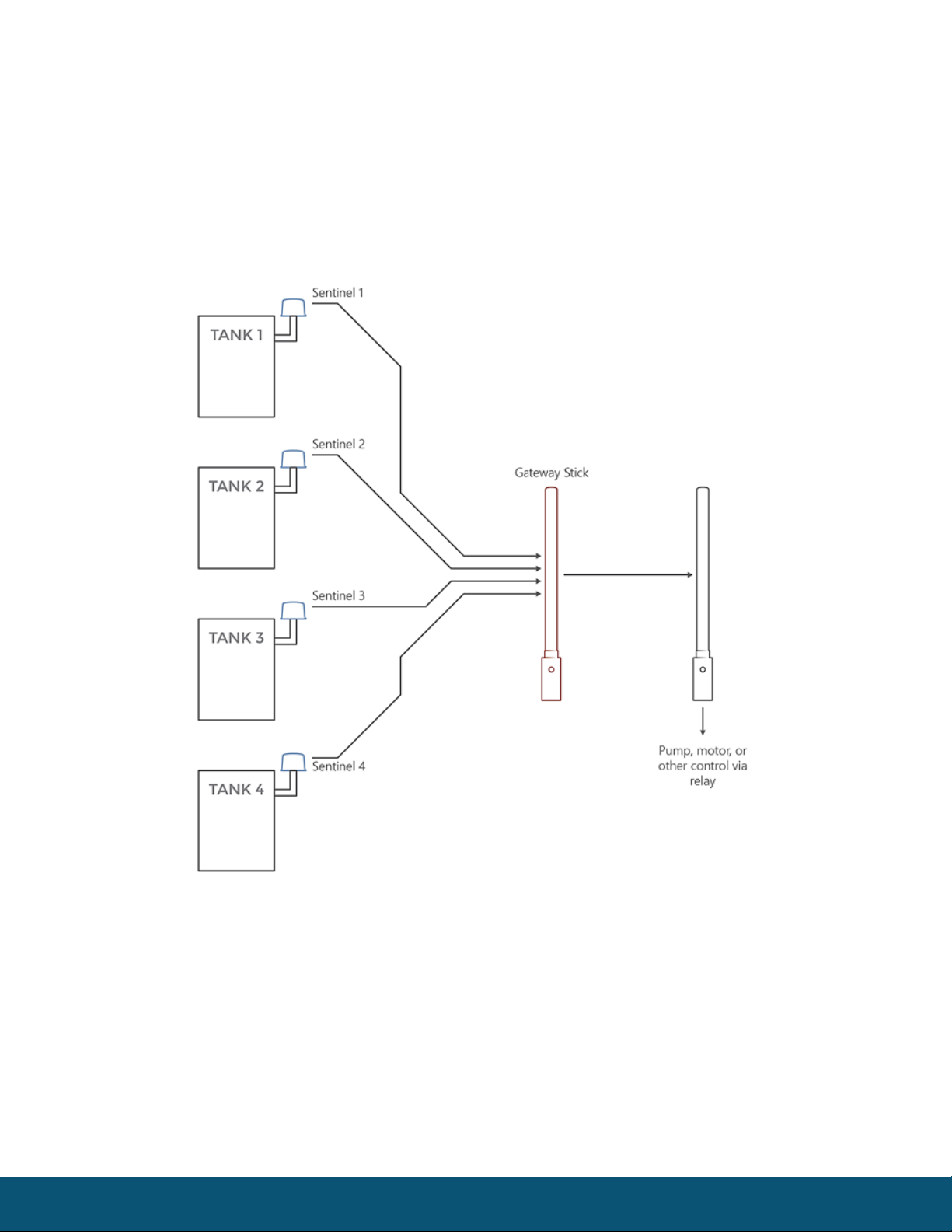
The SignalFire Gateway Stick receives data from multiple remote nodes. It can use the data from
those remote nodes to set the relay output on one or more remote RSD sticks. An example of the topology is
shown in the following figure:
RSD Stick
Rev 4.9 SignalFire Telemetry
15
RSD Configuration
From the Gateway configuration window within the SignalFire Toolkit, go to the Settings
menu and select Remote Shutdown Settings. This will open the RSD configuration window.
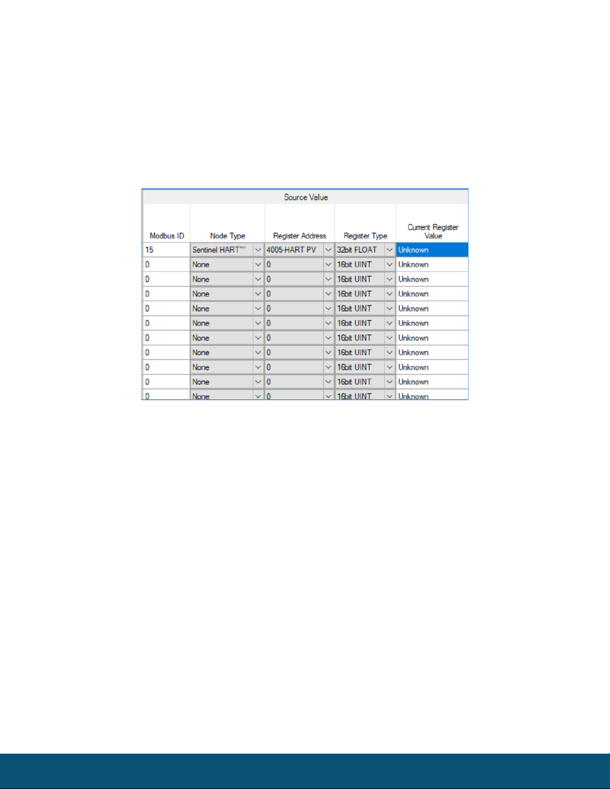
Source Value Section
The ‘Source Value’ section is used to select the source register for the logic rule.
Modbus ID – The Modbus ID of the remote source node.
Node Type – Drop-down list of standard SignalFire remote nodes. Select the type of remote node here, or
select Custom for manual data entry.
Register Address – Select the register address for the data to use for the logic, or manually enter the register
address if Custom was select for the node type.
Register Type – The correct register data type will automatically be selected unless Custom is used. If using a
custom register address, select the correct data type here.
Current Register Value – Displays the value of the selected source data register. Clicking the Update button
will refresh this value.
Rev 4.9 SignalFire Telemetry
16
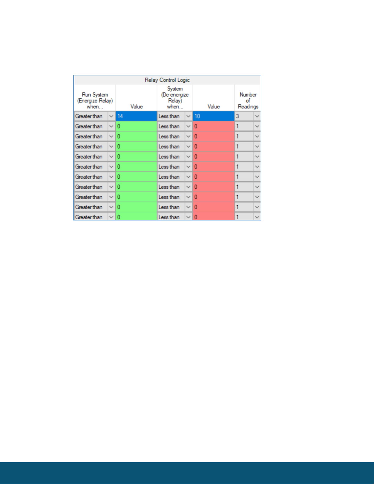
Relay Control Logic Section
The ‘Relay Control Logic’ section is used to set the trigger thresholds for the selected source data
register.
Run System (Energize Relay) – Select the logic operand to use for the “energize” logic evaluation.
Value – The value that the relay will be energized. Note that the energized state is the normal “operating”
state of the relay.
Shutdown System (De-Energize Relay) – The logic operand to use for the “de-energize” logic evaluation.
This will automatically be the opposite of the selection for the energize case. Note that the de-energized state
is the SAFE state of the relay.
Value – The value that the relay will be de-energized. Note that the de-energize state is the “safe” state of the
relay.
Number of Readings – This field contains the number of check-in packets that must be received in a row that
are above (or below) the logic threshold for the de-energize condition. This is useful so that a single (possibly a
glitch) reading does not cause a shut-down. The default is 1 where each check-in will cause the rule to be
evaluated and acted on. A single reading that satisfies the run system (energize) condition will cause the relay
to energize.
Rev 4.9 SignalFire Telemetry
17
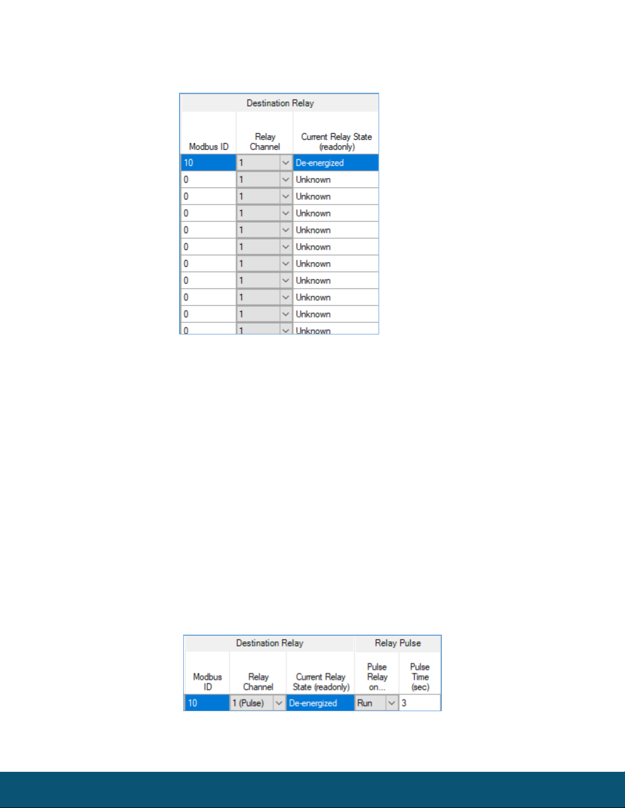
Destination RSD Stick Section
Modbus ID – The Modbus ID of the destination Counter Stick.
Relay Channel – Select the relay channel to switch
Current Relay State – Shows the last value of the relay as reported to the gateway (except for IO1 module).
Clicking the Update button will refresh this value.
After filling out the table click Write Remote Shutdown Settings to Gateway to store the setting in the
gateway Stick.
Relay Pulse
Starting with ToolKit version 2.2.3, and Gateway Firmware version 8.22, destination relays can be configured to
pulse instead of being permanently energized or de-energized. To do so, in the Relay Channel drop-down
menu, select the same relay but in “(Pulse)” mode. Specify whether to pulse during run or shutdown, and
specify the pulse duration.
Rev 4.9 SignalFire Telemetry
18
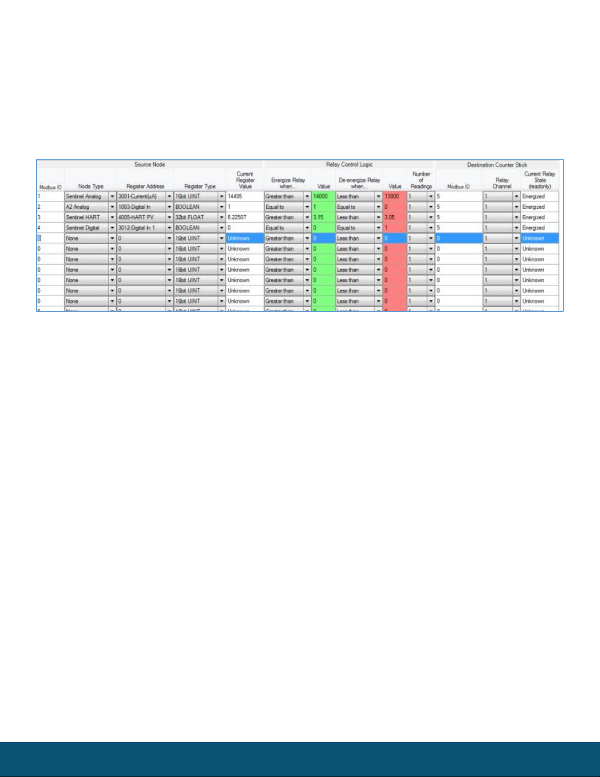
Example
Line 1 has been configured with a source data node as a Sentinel-Analog with the loop current (in
μA) as the selected register. The relay will energize when the loop current is above 1400μA
(14mA) and de-energize when the loop current is below 1300μA (13mA). Note that this
configuration has a 1000μA (1mA) hysteresis factor.
In this example all 4 source nodes are assigned to the same destination Modbus ID and relay channel so the
following statement applies:
If more than one rule is assigned to the same destination RSD Stick and relay channel, then all
the rules must meet the energize condition for the remote relay to be energized. In other
words, the RSD table logic is a Boolean AND.
Alternatively, this means that if any one of the four source node’s logic results in the “de-
energize” condition being true the relay will be de-energized (safe).
RSD Event log
The RSD events will be stored in the gateway internal event log which can be read using the ToolKit.
Additionally, a basic RSD event log containing the last 5 RSD events is available to be read via Modbus from
registers 7000-7024. See the Modbus register map for details. The Modbus event log it not maintained
through gateway resets.

Rev 4.9 SignalFire Telemetry
19
Additional Options
There are two check boxes for additional logic options.
Failsafe Enabled – If this option is selected all rules must have valid data for the relay to be energized. If one
or more of the nodes times-out or does not exist the relay will be de-energized.
If this option is not selected, then a node that is not installed or fails to check in will be ignored and the relay
will be energized using logic only from the units that are active.
Latch De-Energized – If this option is selected the rules may only de-energize the relay. For the relay to be
energized again a Modbus write from a PLC to the gateway for the destination Counter stick relay must occur.
This is useful if manual intervention is required before the relay is energized after an event. In the example
above, a Modbus coil write to Modbus ID 5 relay channel 1 (which is register 1) is required to energize the
relay. See the RSD Stick manual for a detailed register map.
The “Normal” state of the relay or digital output is the un-energized state and this state should be used to
set the controlled system (pump, motor,…) in the “safe” or “off” state.
Output Modules
With the purchase of a SignalFire Analog Output Module or Digital Output Module, the Gateway can directly
control analog (4-20mA, 1-5V) and digital outputs. The outputs for the module can be controlled through the
“Analog/Relay Output Module” window under the Settings menu.
Further information on the modules can be found in their respective manuals.

Rev 4.9 SignalFire Telemetry
20
Modbus Register Remapping
The gateway allows any of the remote register data to be remapped to a single block of
registers available at the Gateway’s Modbus ID (default is 247). This is useful for collecting a
subset of register data from multiple nodes and making it readable in a single block of registers.
Up to 1500 registers can be remapped to the gateway’s Modbus ID starting at register 5000.
To configure the remapping, first select Modbus Register Remapping from the Settings dropdown menu.
Enter the remote Modbus ID and register address to map to each gateway register and click Write to GW to
remap the register(s).
The Data Type, Node Name, Register Value, and Description fields will automatically be filled in by the
gateway once the mapping is written to the gateway.
Table of contents
Other SignalFire Gateway manuals


