Signametrics Corporation SMU2060 User manual

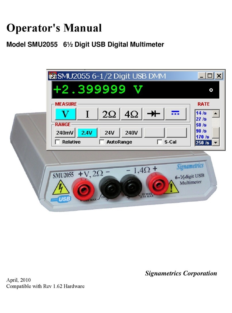
Operator's Manual
Model SMU2060 7-½ Digit Digital USB Multimeter
Model SMU2064 7-½ Digit High Work Load USB Digital Multimeter
Signametrics Corporation
June, 2010
Rev 1.70 driver and Rev F Hardware.

Signametrics 2
CAUTION
In no event shall Signametrics or its Representatives are liable for any consequential damages whatsoever
(including, without limitation, damages for loss of business profits, business interruption, loss of business
information, or other loss) arising out of the use of or inability to use Signametrics products, even if Signametrics
has been advised of the possibility of such damages. Because some states do not allow the exclusion or limitation of
liability for consequential damages, the above limitations may not apply to you.
2004 Signametrics Corp. Printed in the USA. All rights reserved. Contents of this publication must not be
reproduced in any form without the permission of Signametrics Corporation.

3 Signametrics
TABLE OF CONTENTS
1.0 INTRODUCTION .................................................................................................................................................8
1.1 SAFETY CONSIDERATIONS..........................................................................................................................8
1.2 MINIMUM REQUIREMENTS .........................................................................................................................8
1.3 FEATURE SET .............................................................................................................................................8
2.0 SPECIFICATIONS .............................................................................................................................................10
2.1 DC VOLTAGE MEASUREMENT .................................................................................................................10
2.2 DC CURRENT MEASUREMENT..................................................................................................................10
2.3 RESISTANCE MEASUREMENTS..................................................................................................................11
2.3.1 2-wire.....................................................................................................................................11
2.3.2 4-wire.....................................................................................................................................11
2.3.3 6-wire Guarded Resistance Measurement (SMU2064) .........................................................11
2.3.4 Extended Resistance Measurements (SMU2064)...................................................................12
2.3.5 Offset Ohms Measurements (SMU2064)................................................................................12
2.4 AC VOLTAGE MEASUREMENTS................................................................................................................12
2.4.1 AC Voltage True RMS Measurement.....................................................................................12
2.4.2 AC Peak-to-Peak Measurement (SMU2064).........................................................................14
2.4.3 AC Crest Factor Measurement (SMU2064) ..........................................................................14
2.4.4 AC Median Value Measurement (SMU2064) ........................................................................15
2.4.5 Average AC Voltage Measurement (2064) ............................................................................15
2.4.6 Low frequency RMS Voltage Measurement (2064) ...............................................................15
2.5 AC CURRENT MEASUREMENT,TRUE RMS..............................................................................................15
2.6 LEAKAGE MEASUREMENT (SMU2064)....................................................................................................16
2.7 RTD TEMPERATURE MEASUREMENT .......................................................................................................16
2.8 THERMOCOUPLE TEMPERATURE MEASUREMENT.....................................................................................17
2.9 ADDITIONAL COMPONENT MEASUREMENT CAPABILITY ..........................................................................17
2.9.1 Diode Characterization .........................................................................................................17
2.9.2 Capacitance ...........................................................................................................................17
2.9.3 Capacitance, In-Circuit Method (SMU2064) ........................................................................18
2.9.4 Inductance Measurement (SMU2064)...................................................................................18
2.10 TIME MEASUREMENTS ...........................................................................................................................19
2.10.1 Threshold DAC (SMU2064) ................................................................................................19
2.10.2 Frequency and Period Measurements .................................................................................19
2.10.3 Duty Cycle Measurement.....................................................................................................19
2.10.4 Pulse Width..........................................................................................................................19
2.10.5 Totalizer (SMU2064)...........................................................................................................19
2.11 TRIGGER FUNCTIONS..............................................................................................................................20
2.11.1 External Hardware Trigger (at DIN-7 connector) ..............................................................20
2.11.2 Analog Threshold Trigger....................................................................................................20
2.11.3 Long Trigger (SMU2064 with Option ‘R’)..........................................................................20
2.11.4 Delayed Hardware Trigger..................................................................................................20
2.12 MEASUREMENT TIMES ...........................................................................................................................20
2.12.1 Measurement Apertures and Read Interval.........................................................................20
2.12.2 Range and Function Transition Times.................................................................................22
2.13 SOURCE FUNCTIONS (2064) ...................................................................................................................22
2.13.1 DC Voltage, Measure DC Voltage.......................................................................................23
2.13.2 Source DC Voltage, Measure DC Current ..........................................................................23
2.13.3 Source AC Voltage, Measure AC Voltage ...........................................................................23
2.13.4 Source DC Current Measure DC Voltage ...........................................................................24
2.13.5 Pulse Generator...................................................................................................................24
2.14 ACCURACY NOTES .................................................................................................................................24
2.15 OTHER SPECIFICATIONS .........................................................................................................................25
3.0 GETTING STARTED.........................................................................................................................................27
3.1 SETTING UP THE DMM.............................................................................................................................27

Signametrics 4
3.2 INSTALLING THE SOFTWARE.....................................................................................................................27
3.3 INSTALLING THE DMM MODULE .............................................................................................................27
3.4 CALIBRATION FILE ...................................................................................................................................27
3.5 DMM TERMINALS....................................................................................................................................28
3.6 DMM REAR PANEL..................................................................................................................................30
3.7 STARTING THE CONTROL PANEL ..............................................................................................................30
3.8 USING THE CONTROL PANEL ....................................................................................................................31
4.0 DMM OPERATION AND MEASUREMENTS TUTORIAL.........................................................................34
4.1 VOLTAGE MEASUREMENT........................................................................................................................34
4.1.1 DC Voltage Measurements ....................................................................................................34
4.1.2 True RMS AC Voltage Measurements ...................................................................................34
4.1.3 AC Peak-to-Peak and Crest Factor (SMU2064) ...................................................................35
4.1.4 AC Median Value Measurement (SMU2064) ........................................................................35
4.1.5 Average AC Voltage Measurement (2064) ...........................................................................35
4.1.6 Low frequency RMS Voltage Measurement (2064) ..............................................................35
4.2 CURRENT MEASUREMENTS ......................................................................................................................36
4.2.1 Extended DC Current Measurements (SMU2064) ................................................................36
4.2.2 Improving DC Current Measurements ..................................................................................36
4.2.3 DC Current Measurements at a specific voltage...................................................................36
4.3 RESISTANCE MEASUREMENTS..................................................................................................................36
4.3.1 2-Wire Ohm Measurements ...................................................................................................37
4.3.2 4-Wire Ohm Measurements ...................................................................................................37
4.3.3 Using Offset Ohms function (SMU2064)...............................................................................38
4.3.4 6-wire Guarded Resistance Measurement (SMU2064) .........................................................38
4.3.5 Extended Resistance Measurements (SMU2064)...................................................................39
4.3.6 Effects of Thermo-Voltaic Offset............................................................................................40
4.3.7 Guarding High Value Resistance Measurements (SMU2064)...............................................41
4.4 LEAKAGE MEASUREMENTS (SMU2064) ..................................................................................................42
4.5 ANATOMY OF MEASUREMENT TIMING ......................................................................................................43
4.5.1 Aperture.................................................................................................................................43
4.5.2 Read Interval..........................................................................................................................43
4.6 RTD TEMPERATURE MEASUREMENT (SMU2064) ...................................................................................44
4.7 INTERNAL TEMPERATURE (SMU2064) ....................................................................................................44
4.8 DIODE CHARACTERIZATION .....................................................................................................................44
4.9 CAPACITANCE MEASUREMENT,CHARGE BALANCE METHOD...................................................................44
4.10 IN-CIRCUIT CAPACITANCE MEASUREMENT (SMU2064)........................................................................45
Additional considerations...............................................................................................................45
4.11 MEASURING THE RESISTANCE IN A SERIES RC NETWORK (2064)............................................................45
4.12 INDUCTANCE MEASUREMENT (SMU2064) ............................................................................................46
4.13 CHARACTERISTIC IMPEDANCE MEASUREMENT (SMU2064) ..................................................................47
4.14 TRIGGER OPERATION .............................................................................................................................47
4.14.1 External Hardware Trigger.................................................................................................47
4.14.2 Analog Threshold Trigger....................................................................................................48
4.14.3 Software Initiated Triggered Operations.............................................................................49
4.14.4 External Trigger and Sync Handshake................................................................................51
4.15 TIME AND FREQUENCY MEASUREMENTS ...............................................................................................51
4.15.1 Threshold DAC (SMU2064) ................................................................................................51
4.15.2 Using the Frequency counter...............................................................................................52
4.15.3 Duty Cycle Measurement (SMU2064).................................................................................53
4.15.4 Pulse Width (SMU2064)......................................................................................................53
4.15.5 Totalizer Event Counter (SMU2064)...................................................................................53
4.16 SOURCE FUNCTIONS (2064) ...................................................................................................................54
4.16.1 DC Voltage Source ..............................................................................................................54
4.16.2 Source DC Voltage and measure DC Current.....................................................................54
4.16.3 AC Voltage Source...............................................................................................................56
4.16.4 DC Current Source..............................................................................................................56
4.16.5 Source Current - Measure Voltage......................................................................................57
4.16.6 Pulse Generator...................................................................................................................57
4.17 INTERFACING TO AN EXTERNAL DEVICE .................................................................................................58

5 Signametrics
4.18 MEASURING THERMOCOUPLES’TEMPERATURE .....................................................................................59
4.19 AUXILIARY VDC INPUTS (2064) ............................................................................................................60
5.0 WINDOWS INTERFACE..................................................................................................................................63
5.1 DISTRIBUTION FILES ................................................................................................................................63
5.1.1 Calibration Record ................................................................................................................63
5.2 USING THE SMU2060 DRIVER WITH C++ OR SIMILAR SOFTWARE..........................................................64
5.3 VISUAL BASIC DMM PANEL APPLICATION..............................................................................................65
5.3.1 Visual Basic Simple Application............................................................................................65
5.4 WINDOWS DLL DEFAULT MODES AND PARAMETERS..............................................................................67
5.5 USING THE SMU2060 DLL WITH LABWINDOWS/CVI.............................................................................67
5.6 WINDOWS COMMAND LANGUAGE ...........................................................................................................67
DMMArmAnalogTrigger ................................................................................................................68
DMMArmTrigger............................................................................................................................69
DMMBurstBuffRead .......................................................................................................................70
DMMBurstRead..............................................................................................................................71
DMMCalibrate................................................................................................................................72
DMMCleanRelay ............................................................................................................................72
DMMClearMinMax ........................................................................................................................73
DMMCloseUSB...............................................................................................................................73
DMMDelayedTrigger .....................................................................................................................74
DMMDisableTrimDAC...................................................................................................................75
DMMDisarmTrigger.......................................................................................................................75
DMMDutyCycleStr .........................................................................................................................76
DMMErrString................................................................................................................................76
DMMFrequencyStr.........................................................................................................................77
DMMGetACCapsR .........................................................................................................................77
DMMGetAperture...........................................................................................................................78
DMMGetAverageVAC ....................................................................................................................79
DMMGetBufferSize.........................................................................................................................79
DMMGetBusInfo.............................................................................................................................80
DMMGetCalDate............................................................................................................................80
DMMGetdB.....................................................................................................................................82
DMMGetdBStr................................................................................................................................82
DMMGetCJTemp............................................................................................................................83
DMMGetCounterRange..................................................................................................................83
DMMGetDeviation .........................................................................................................................84
DMMGetDeviatStr..........................................................................................................................84
DMMGetDevLocation.....................................................................................................................85
DMMGetDiffMnMxStr....................................................................................................................86
DMMGetFuncRange.......................................................................................................................86
DMMGetFunction...........................................................................................................................87
DMMGetGrdVer.............................................................................................................................87
DMMGetHwVer..............................................................................................................................88
DMMGetHwOption.........................................................................................................................88
DMMGetID.....................................................................................................................................89
DMMGetLowFreqVRMS ................................................................................................................89
DMMGetManDate..........................................................................................................................90
DMMGetMax..................................................................................................................................90
DMMGetMaxStr .............................................................................................................................91
DMMGetMin...................................................................................................................................91
DMMGetMinStr..............................................................................................................................92
DMMGetNumDevices.....................................................................................................................93
DMMGetRange...............................................................................................................................93
DMMGetReadInterval ....................................................................................................................94
DMMGetSourceFreq ......................................................................................................................94
DMMGetStoredReading .................................................................................................................95
DMMGetSourceMode.....................................................................................................................95
DMMGetTCType.............................................................................................................................96
DMMGetTrigger.............................................................................................................................96

Signametrics 6
DMMGetTriggerInfo.......................................................................................................................97
DMMGetType .................................................................................................................................98
DMMGetVer ...................................................................................................................................98
DMMInit .........................................................................................................................................99
DMMIsAutoRange ..........................................................................................................................99
DMMIsInitialized..........................................................................................................................100
DMMIsRelative.............................................................................................................................100
DMMLongTrigger ........................................................................................................................101
DMMLongTrigRead......................................................................................................................102
DMMOpenCalACCaps.................................................................................................................103
DMMOpenTerminalCal................................................................................................................103
DMMOpenUSB.............................................................................................................................104
DMMOutputSync ..........................................................................................................................104
DMMPeriodStr .............................................................................................................................105
DMMQuickInit..............................................................................................................................107
DMMRead.....................................................................................................................................107
DMMReadBuffer...........................................................................................................................108
DMMReadBufferStr......................................................................................................................109
DMMReadCJTemp .......................................................................................................................109
DMMReadCrestFactor .................................................................................................................110
DMMReadDutyCycle....................................................................................................................111
DMMReadSR ................................................................................................................................111
DMMReadFrequency....................................................................................................................112
DMMReadHiLoSense ...................................................................................................................113
DMMReadHiSense........................................................................................................................113
DMMReadInductorQ....................................................................................................................114
DMMReadInductorR.....................................................................................................................114
DMMReadLoSense .......................................................................................................................115
DMMReadMeasurement...............................................................................................................116
DMMReadMedian.........................................................................................................................116
DMMReadNorm............................................................................................................................117
DMMReadNsamples.....................................................................................................................118
DMMReadPeakToPeak.................................................................................................................118
DMMReadPeriod..........................................................................................................................119
DMMReadStr................................................................................................................................119
DMMReadTestV............................................................................................................................120
DMMReadTotalizer ......................................................................................................................121
DMMReadWidth...........................................................................................................................121
DMMReady...................................................................................................................................122
DMMSetACCapsDelay .................................................................................................................122
DMMSetACCapsLevel..................................................................................................................123
DMMSetACVSource .....................................................................................................................124
DMMSetAperture..........................................................................................................................125
DMMSetAutoRange ......................................................................................................................125
DMMSetBuffTrigRead ..................................................................................................................126
DMMSetCapsAveSamp.................................................................................................................127
DMMSetCJTemp...........................................................................................................................128
DMMSetCompThreshold ..............................................................................................................128
DMMSetCounterRng.....................................................................................................................129
DMMSetDCISource......................................................................................................................130
DMMSetDCVSource.....................................................................................................................131
DMMSetFastRMS.........................................................................................................................132
DMMSetFuncRange......................................................................................................................132
DMMSetFunction..........................................................................................................................133
DMMSetInductFreq......................................................................................................................133
DMMSetOffsetOhms.....................................................................................................................134
DMMSetPLC.................................................................................................................................134
DMMSetPulseGen.........................................................................................................................135
DMMSetRange..............................................................................................................................136
DMMSetReadInterval...................................................................................................................137

7 Signametrics
DMMSetReference........................................................................................................................138
DMMSetRelative...........................................................................................................................138
DMMSetRTD ................................................................................................................................139
DMMSetSensorParams.................................................................................................................139
DMMSetSourceMode....................................................................................................................140
DMMSetSourceRes.......................................................................................................................141
DMMSetSync ................................................................................................................................141
DMMSetTCType ...........................................................................................................................143
DMMSetTempUnits.......................................................................................................................143
DMMSetTrigPolarity....................................................................................................................144
DMMSetTrigRead.........................................................................................................................144
DMMSetTrimDAC ........................................................................................................................146
DMMStartTotalizer.......................................................................................................................146
DMMStopTotalizer .......................................................................................................................147
DMMTerminate.............................................................................................................................148
DMMTrigger.................................................................................................................................148
DMMTriggerBurst........................................................................................................................149
DMMUnlockCounter ....................................................................................................................150
DMMWaitForTrigger...................................................................................................................151
DMMWidthStr...............................................................................................................................151
5.7 CALIBRATION AND SERVICE COMMANDS ...............................................................................................153
AC_zero ........................................................................................................................................153
DMMLoadCalFile.........................................................................................................................154
SetGain..........................................................................................................................................154
GetGain.........................................................................................................................................155
GetOffset.......................................................................................................................................155
SetFcomp ......................................................................................................................................156
SetOffset........................................................................................................................................157
Linearize_AD................................................................................................................................157
Read_ADcounts ............................................................................................................................158
WrCalFileToStore.........................................................................................................................158
WrCalStoreToFile.........................................................................................................................159
DMMGetSupplyV..........................................................................................................................159
5.8 SERVICE COMMANDS .............................................................................................................................161
GrdXingTest..................................................................................................................................161
ClearBuffer ...................................................................................................................................162
5.9 ERROR CODES ........................................................................................................................................162
5.10 WARNING CODES .................................................................................................................................163
5.11 PARAMETER LIST .................................................................................................................................163
5.11.1 Measurement and Source Functions..................................................................................163
5.11.2 Composite Function-Range ...............................................................................................164
5.11.3 Function Values.................................................................................................................166
5.11.4 Range Values .....................................................................................................................167
5.11.5 Aperture parameters..........................................................................................................168
5.11.6 Additional parameters .......................................................................................................169
6.0 MAINTENANCE ..............................................................................................................................................170
6.1 PERFORMANCE TESTS ............................................................................................................................171
6.2 DC VOLTAGE TEST ................................................................................................................................171
6.3 RESISTANCE TEST,2-WIRE .....................................................................................................................172
6.4 RESISTANCE TEST,4-WIRE .....................................................................................................................173
6.5 AC VOLTAGE TEST ................................................................................................................................174
6.6 DC CURRENT TEST ................................................................................................................................175
6.7 AC CURRENT TEST ................................................................................................................................176
6.8 CAPACITANCE TEST (SMU2064 ONLY)..................................................................................................177
6.8 INDUCTANCE TEST (SMU2064 ONLY)....................................................................................................178
6.9 FREQUENCY COUNTER TEST (SMU2064 ONLY)....................................................................................179
6.10 CALIBRATION .......................................................................................................................................180
7.0 WARRANTY AND SERVICE.........................................................................................................................182

8.0 ACCESSORIES.................................................................................................................................................182
1.0 Introduction
Congratulations! You have purchased a Personal Computer (PC) USB with analog and systems performance that
rivals the best Digital Multimeters on the market. These all-in-one Digital Multimeters (DMM’s) are easy to setup
and use, have sophisticated analog and digital circuitry to provide very repeatable and super accurate measurements,
and are protected to handle any unexpected situations your measurement environment may encounter. To get years
of reliable service from these DMM’s, please take a few moments and review this manual before installing and
using this precision instrument.
This manual describes the SMU2060 and SMU2064 DMMs.
1.1 Safety Considerations
Safety Considerations
The SMU2060 series of USB Digital Multimeters (DMMs) are capable of measuring up to 330 VDC or
330 VAC across the Volt HI and LO terminals, and can also measure common mode signals that "float"
the DMM above EARTH ground by up to 330 VDC or 250 VAC. When making common mode
measurements, the majority of the circuits inside the DMM are at the common mode voltage. These
voltages can be lethal.
The DMM enclosure must not be tempered or disassembled for any reason. Doing so will result in
performance degradation and will present a safety risk. Improper handeling of these products can
result in lethal voltages that may effect the computer this product is connected to.
Warning
No probes or any other wiring should be connected to the DMMs during installation or removal of
the USB to the DMM or to the Computer. Not doing so may apply lethal measurement voltages to
your computer and USB cable, causing electrocution and/or damage to your computer and/or your
DMM.
To avoid shock hazard, connect the USB cable only to a computer that has its power connector
connected to a power receptacle with an earth safety ground.
When making any measurements above 50 VDC or 40 VAC, only use Safety Test Leads. Examples
of these are the Signametrics Basic Test Leads and Deluxe Test Leads, offered as an accessory with the
Signametrics DMM’s.
1.2 Minimum Requirements
These USB DMMs are precision plug-in modules that are compatible with personal computers (PCs). It requires as
a minimum a Pentiums computer. A mouse or a compatible pointing device must be installed when controlling the
DMM from the Windows Control Panel provided with this product. These DMMs comes with a Windows' DLL,
for operation with Windows' Version 95/98/Me/2000/XP and Milenium.
1.3 Feature Set
Signametrics 8
The base unit, the SMU2060, has traditional 7-1/2 digit features and it can be used as a general purpose DMM,
where accuracy and speed are important. The High Workload Multi Function SMU2064 adds timing, capacitance,
inductance, sourcing , leakage and more speed. With its specialized measurements, it can replace several costly
instruments, shrinking the size and cost of a test system. It is possible to deploy several SMU2060s, SMU2064s and

9 Signametrics
SMU2055 DMMs in a single computer, in any mix. Multiple units add both, overall system throughput and
comlexity.
SMU2060 and SMU2064 7½ Digit DMM’s feature table:
Function SMU2055 SMU2060 SMU2064
DCV five ranges 240mV to 330V (-330V)
ACV five ranges 240mV to 330V (-330V)
2-Wire Ohms, six ranges 240 to 24 M
4-Wire Ohms, six ranges 240 to 24 M
DC current, four ranges 2.4 mA to 2.4 A
AC current, four ranges 2.4 mA to 2.4 A
Diode V/I characteristics at 100 A to 1mA (plus 10mA)
Auto range, Relative
Min/Max, dB and percent deviation functions
On board measurement buffer
External and threshold trigger
Thermocouples types; B, E, J, K, N, R, S, T
High Dynamic range; +24,000,000 counts
Frequency / Period measurement
Measurement rate: (rdngs/sec) 375 1350 20,000
Capacitance, ramp type, eight ranges, 1 nF to 10 mF
RTD types: pt385, 3911, 3916, 3926, Copper, variable Ro
Internal DMM temperature sensor
Component Handler Interface (for volume prouction)
Capacitance, In-Circuit method five ranges, 24nF to 2.4mF
Inductance, six ranges 33 H to 3.3 H
Offset Ohms
Pulse width, pos./neg., & duty cycle
Totalizer/event counter
Variable threshold DAC; all timing measure.
Peak to Peak, Crest factor, Median
Six wire Ohms (with force/sense)
DCV source to ±10.0 V
ACV source 0 to 20 V pk-pk, 0.5 Hz to 200 KHz
DC current source, 1 nA to 12.5 mA
Leakage at ±10.0V, 240nA, 2.4uA and 25uA ranges.
2-Wire Ohms two additional ranges 24 and 240 M
4-Wire Ohms additional range 24
Extended Resistance with V&I limits (to 100G)
DC Current , additional ranges 240nA, 2.4A, 24A, 240A
Two auxiliary VDC inputs
Source 0 - ±10V / Measure to 0 - ±24mA
Stimulate and Measure Load cells and Strain gauges
Average AC Voltage, 240mV, 2.4V, 24V, 240V, 330V (1Hz to 1kHz)
Low frequency true RMS (0.2Hz to 66Hz)

Signametrics 10
2.0 Specifications
The following specifications should be considered under the environment specified.
To meet its specified accuracy specs, allow a warm up for at least one-half hour.
It is important to note that a DMM specified range is expressed as a numeric value indicating the highest
absolute voltage that can be measured. The lowest value that can be detected, or sensitivity is expressed
by the corresponding resolution for the range.
2.1 DC Voltage Measurement
Input Characteristics
Input Resistance 240 mV, 2.4 V Ranges: >10 G, with typical leakage of 50pA
Input Resistance 24 V, 240 V, 330V Ranges: 10.00 M
Accuracy ± (% of reading + Volts) [1]
Range Full Scale
7-½ Digits
Resolution 24 hours
23C 1C
90 Days
23C 5C
One Year 23C
5C
240 mV 240.00000 mV 10 V 0.003 + 1 V 0.004 + 1.5 V 0.005 + 2 V
2.4 V 2.4000000 V 100 V 0.002 + 3 V 0.0025 + 4 V 0.003 + 5 V
24 V 24.000000 V 1 V 0.004 + 120 V 0.005 + 130 V 0.006 + 150 V
240 V 240.00000 V 10 V0.003 + 250 V 0.004 + 300 V 0.005 + 0.5 mV
330 V 330.00000 V 10 V0.0075 + 550 V 0.01+ 700 V 0.015 + 0.8 mV
[1] With Aperture set to 0.5 Sec, and within one hour from Self Calibration (S-Cal).
For resolution at smaller Apertures, see the following table. Use this table for DC Volts, DC current and
Resistance measurements.
Measurement Aperture
SMU2060, SMU2064
Maximum reading
rate
Resolution
Aperture > 0.5 s 2 / second 7-1/2 digits 25 bits
Aperture 10 ms 100 / second 6-1/2 digits 22 bits
Aperture 625s 1200 / second 5-1/2 digits 18 bits
Aperture > 2.5us [2] 20,000 / second [2] 4 digits 14 bits
[2] Available only with the SMU2064.
DCV Noise Rejection Normal Mode Rejection, at 50, 60, or 400 Hz ± 0.5%, is better than 95 dB for
apertures of 0.160s and higher. Common Mode Rejection (with 1 klead imbalance) is better than 120
dB for these conditions.
2.2 DC Current Measurement
Input Characteristics
Number of shunts Five in SMU2064, two in the SMU2060
Burden Voltage 240mV max.
Protected with 2.5A Fast blow fuse
Accuracy ± (% of reading + Amps) [1]
Range Full Scale
Reading
Resolution Max Burden
Voltage
24 hours
23C 5C
90 Days
23C 5C
One Year
23C 5C
240 A [2] 240.0000 A 0.1 pA 100 V 0.07 + 40pA 0.1 + 45pA 0.17 + 60pA
2.4 A [2] 2.400000 A 1 pA 100 V 0.05 + 70pA 0.08 + 90pA 0.21 + 150pA
24 A [2] 24.00000 A 10 pA 100 V 0.05 + 400pA 0.08 + 600pA 0.13 + 0.8nA
240 A [2] 240.000 A 10 A 2.5mV 0.052 + 200 A 0.07 + 300 A 0.1 + 400 A
2.4 mA 2.40000 mA 10 A 25mV 0.05 + 300 A 0.06 + 400 A 0.07 + 550 A
24 mA 24.0000 mA 100 A 250mV 0.05 + 350 A 0.065 + 450 A 0.08 + 550 A
240 mA 240.000 mA 1 A 55mV 0.05 + 50 A 0.055 + 60 A 0.065 + 80 A
2.4 A 2.40000 A 10 A 520mV 0.3 + 60 A 0.4 + 70 A 0.45 + 90 A
[1] With Aperture set to 0.96 Sec, and within one hour from Zero (Relative control).

11 Signametrics
[2] Available only with the SMU2064.
2.3 Resistance Measurements
Input Characteristics
Number of Current Sources seven in SMU2064, five in the SMU2060
Burden Voltage 240mV or 2.4V max, depending on range.
Range Full Scale Reading Resolution Test current Maximum Test Voltage (at Full Scale)
24 [1] 24.000000 1 10 mA 240mV
240 240.00000 10 1 mA 240mV
2.4 k2.4000000 k100 1 mA 2.4V
24 k24.000000 k1 m100 A 2.4V
240 k240.00000 k10 m10 A 2.4V
2.4 M2.4000000 M100 m1 A 2.4V
24 M24.0000 M100 100 nA 2.4V
240 M[1] 240.000 M1 k4 nA 1.0V
[1] Ranges are only available in the SMU2064.
2.3.1 2-wire
Accuracy ± (% of reading + ) [1]
Range 24 hours 23C 1C 90 Days 23C 5C One Year 23C 5C
24 0.0038 + 1.4 m[2] 0.005 + 1.6 m[2] 0.008 + 2 m[2]
240 0.0037 + 4.5 m[2] 0.0046 + 5 m[2] 0.007 + 6 m[2]
2.4 k0.0023 + 28 m0.004 + 32 m0.006 + 33 m
24 k0.0025 + 300 m0.004 + 330 m0.006 + 350 m
240 k0.0055 + 3.2 0.006 + 4 0.007 + 5
2.4 M0.018 + 40 0.03 + 50 0.04 + 70
24 M0.12 + 400 0.13 + 500 0.2 + 600
240 M0.8 + 20 k1.0 + 30 k1.3 + 50 k
[1] With Aperture set to 0.5 Sec, and within one hour from Self Calibration (S-Cal).
[2] Use of S-Cal and Relative to improve measurement floor.
2.3.2 4-wire
Accuracy ± (% of reading + ) [1]
Range Maximum Lead
Resistance
24 hours
23C 1C
90 Days
23C 5C
One Year
23C 5C
24 50 0.0038 + 0.7 m[2] 0.005 + 0.8 m[2] 0.008 + 1 m[2]
240 500 0.0037 + 3 m[2] 0.0046 + 4 m[2] 0.007 + 5 m[2]
2.4 k500 0.0023 + 28 m0.004 + 32 m0.006 + 33 m
24 k5 k0.0025 + 300 m0.004 + 330 m0.006 + 350 m
240 k50k 0.0055 + 3.2 0.007 + 4 0.007 + 5
2.4 M50 k0.018 + 40 0.03 + 50 0.04 + 70
24 M50 k0.12 + 400 0.13 + 500 0.2 + 600
[1] With Aperture set to 0.5 Sec, and within one hour from Self Calibration (S-Cal).
[2] Use of Relative to facilitate indicated floor (adder part of spec).
2.3.3 6-wire Guarded Resistance Measurement (SMU2064)
This is an in-circuit forced guard measurement method, as implemented in ICT testers. Add this typical
additional error to the above specification.
Accuracy ± (% of reading + )
Range Max Guard forced current One Year 23C 5C [1] (adder)
24 20 mA 0.3 + 4 m
240 20 mA 0.003 + 20 m
2.4 k20 mA 0.005 + 100 m
24 k100 A 0.03 + 1
240 k10 A 0.35 + 10
24 M1 A 0.85 + 1000
[1] This table should be used in conjunction with the 2-wire and 4-wire table above.

Signametrics 12
2.3.4 Extended Resistance Measurements (SMU2064)
Characteristics
Test Voltage Adjustable between -10V and +10V in 5mV steps
Accuracy ± (% of reading + Amps) [1]
Range Measurement range Resol
ution
Current Limit [3] 90 Days
23C 5C
One Year 23C
5C
400k1kto 100M1025µA 0.2 + 500.33 + 90
4M10kto 1G1002.5µA 0.3 + 3500.43 + 550
40M100kto 10G1k250nA 0.4 + 3k0.55 + 4.5k
[1] With Aperture set to 0.5 Sec, and within one hour from Zero (Relative control).
[2] Multiply “% of reading” by 1/Voltage Source for applied voltages below 1V
[3] Limit is reached when the test current exceeds the Current Limit, or it is below 0.04% of this value.
2.3.5 Offset Ohms Measurements (SMU2064)
The purpose of Offset Ohms is to compensate for errors due to DC voltages which are in series with the
resistance being measured. DMMSetOffsetOhms() function provides the means to control this
operation. It is disabled by default.
Characteristics
Offset correction range: 240mV or 2.4V depending on selected range
Application: 2-Wire and 4-Wire Ohms
Offset voltage: Depends on head-room; range and measured resistance value.
Range Vo limits [1] Measurement limits [2]
24& 240-230mV to 230mV I*R + Vo < +220mV
2.4k to 24M-2.3V to 2.3V I*R + Vo < +2.2V
[1] With resistance, R, less than 10% of range.
[2] R – Measured resistance, I – Test current, Voofset – Offset Voltage
2.4 AC Voltage Measurements
Input Characteristics
Input Resistance 1 M, shunted by < 300 pF, all ranges
Max. Crest Factor 4 at Full Scale, increasing to 7 at Lowest Specified Voltage
AC coupled Specified range: 10 Hz to 100 kHz
Typical Settling time < 0.5 sec to within 0.1% of final value
Typical Settling time, Fast RMS < 0.05 sec to within 0.1% of final value
2.4.1 AC Voltage True RMS Measurement
Range Full Scale 7-½ Digits Lowest specified Voltage Resolution
240 mV 240.0000 mV 5 mV [1] 100 V
2.4 V 2.400000 V 20 mV 1 V
24 V 24.00000 V 200 mV 10 V
240 V 240.0000 V 2 V 100 V
330 V 330.0000 V 2.5 V 100 V
[1] Between 5 mV and 10 mV, add 100 V additional errors to the accuracy table below.
[2] Signal is limited to 8x10⁶Volt Hz Product. For example, the largest frequency input at 250 V is 32 kHz, or
8x10⁶Volt x Hz.
ACV Noise Rejection Common Mode rejection, for 50 Hz or 60 Hz with 1 kimbalance in either lead, is better
than 60 dB.

13 Signametrics
AC Volts Accuracy with Fast RMS disabled (default). With Fast RMS disabled, settling time to
rated accuracy is within 0.5s:
Accuracy ± (% of reading + Volts) [1]
Range Frequency 24 hours
23C 1C
90 Days
23C 5C
One Year
23C 5C
10 Hz - 20 Hz 3.0 + 350 V 3.1 + 380 V 3.2 + 430 V
20 Hz - 47 Hz 0.37 + 150 V 0.38 + 170 V 0.4 + 200 V
47 Hz - 10 kHz 0.2 + 100 V 0.21 + 110 V 022 + 120 V
10 kHz - 50 kHz 0.25 + 160 V 0.26 + 200 V 0.27 + 230 V
240 mV
50 kHz - 100 kHz 1.9 + 350 V 1.95 + 370 V 2.0 + 400 V
10 Hz - 20 Hz 3.0 + 2 mV 3.1 + 2.2 mV 3.2 + 2.5 mV
20 Hz - 47 Hz 0.37 + 1.3 mV 0.38 + 1.5 mV 0.4 + 1.7 mV
47 Hz - 10 kHz 0.05 + 1 mV 0.055 + 1.1 mV 0.065 + 1.2 mV
10 kHz - 50 kHz 0.32 + 1.2 mV 0.33 + 1.3 mV 0.35 + 1.5 mV
2.4 V
50 kHz - 100 kHz 1.9 + 1.5 mV 2.0 + 1.7 mV 2.1 + 2 mV
10 Hz - 20 Hz 3.0 + 14 mV 3.1 + 16 mV 3.3 + 20 mV
20 Hz - 47 Hz 0.37 + 12 mV 0.37 + 14 mV 0.4 + 16 mV
47 Hz - 10 kHz 0.06 + 10 mV 0.065 + 11 mV 0.073 + 13 mV
10 kHz - 50 kHz 0.18 + 18 mV 0.2 + 21 mV 0.22 + 25 mV
24 V
50 kHz - 100 kHz 1.3 + 30 mV 1.4 + 35 mV 1.5 + 40 mV
10 Hz - 20 Hz 3.0 + 140 mV 3.1 + 160 mV 3.3 + 200 mV
20 Hz - 47 Hz 0.37 + 120 mV 0.38 + 130 mV 0.4 + 150 mV
47 Hz - 10 kHz 0.04 + 100 mV 0.045 + 110 mV 0.06 + 130 mV
10 kHz - 50 kHz 0.28 + 150 mV 0.29 + 170 mV 0.30 + 200 mV
240 V
50 kHz - 100 kHz 1.4 + 200 mV 1.5 + 240 mV 1.6 + 300 mV
10 Hz - 20 Hz 3.0 + 200 mV 3.1 + 160 mV 3.3 + 200 mV
20 Hz - 47 Hz 0.43 + 180 mV 0.44 + 200 mV 0.45 + 250 mV
47 Hz - 10 kHz 0.07 + 150 mV 0.08 + 200 mV 0.09 + 230 mV
10 kHz - 50 kHz 0.28 + 200 mV 0.30 + 250 mV 0.32 + 300 mV
330 V
50 kHz - 100 kHz 1.3 + 270 mV 2.4 + 350 mV 1.6 + 400 mV
[1] With Aperture set to 0.5 Sec
AC Volts Accuracy with Fast RMS enabled.
Fast RMS settles to rated accuracy within 50ms.

Signametrics 14
Accuracy ± (% of reading + Volts) [1]
Range Frequency 24 hours
23C 1C
90 Days
23C 5C
One Year
23C 5C
350 Hz - 800 Hz 0.6 + 150 V 0.65 + 170 V 0.7 + 200 V
800 Hz - 10 kHz 0.13 + 100 V 0.14 + 110 V 0.15 + 120 V
10 kHz - 50 kHz 0.55 + 160 V 0.6 + 200 V 0.63 + 230 V
240 mV
50 kHz - 100 kHz 5.3 + 350 V 5.4 + 370 V 5.6 + 400 V
350 Hz - 800 Hz 0.93 + 1.3 mV 0.96 + 1.5 mV 1.0 + 1.7 mV
800 Hz - 10 kHz 0.068 + 1 mV 0.075 + 1.1 mV 0.08 + 1.2 mV
10 kHz - 50 kHz 0.62 + 1.2 mV 0.65 + 1.3 mV 0.70 + 1.5 mV
2.4 V
50 kHz - 100 kHz 5.1 + 1.5 mV 5.2 + 1.7 mV 5.3 + 2 mV
350 Hz - 800 Hz 0.93 + 12 mV 0.96 + 14 mV 1.0 + 16 mV
800 Hz - 10 kHz 0.065 + 10 mV 0.068 + 11 mV 0.073 + 13 mV
10 kHz - 50 kHz 0.31 + 18 mV 0.33 + 21 mV 0.35 + 25 mV
24 V
50 kHz - 100 kHz 2.0 + 30 mV 2.2 + 35 mV 2.4 + 40 mV
350 Hz - 800 Hz 0.93 + 120 mV 0.96 + 130 mV 1.0 + 150 mV
800 Hz - 10 kHz 0.062 + 100 mV 0.065 + 110 mV 0.08 + 130 mV
10 kHz - 50 kHz 0.32 + 150 mV 0.4 + 170 mV 0.45 + 200 mV
240 V
50 kHz - 100 kHz 2.5 + 200 mV 2.8 + 240 mV 3.2 + 300 mV
350 Hz - 800 Hz 1.0 + 180 mV 1.1 + 200 mV 1.1 + 250 mV
800 Hz - 10 kHz 0.065 + 150 mV 0.07 + 200 mV 0.08 + 230 mV
10 kHz - 50 kHz 0.34 + 200 mV 0.45 + 250 mV 0.5 + 300 mV
330 V
50 kHz - 100 kHz 2.5 + 270 mV 2.8 + 350 mV 3.2 + 400 mV
[1] With Aperture set to 0.16 Sec
2.4.2 AC Peak-to-Peak Measurement (SMU2064)
Measures the peak-to-peak value of a repetitive waveform.
ACV
Range
Lowest specified
input voltage (Vp-p)
Full Scale [2]
reading (Vp-p)
Resolution Typical Accuracy 23C 5C
One Year [1]
240 mV 0.1 V 1.900 V 1 mV 0.5 3 mV
2.4 V 1.0 V 16.00 V 10 mV 0.5 ± 40 mV
24 V 10 V 190.0 V 100 mV 0.5 ± 700 mV
240 V 100 V 850.0 V 1 V 0.55 ± 6 V
[1] Signal frequency range 30 Hz to 60 kHz.
[2] USB power level greatly effects full scale reading.
2.4.3 AC Crest Factor Measurement (SMU2064)
Measures the crest factor (CF) of a repetitive waveform
ACV
Range
Lowest specified
input voltage
(Vp-p)
Highest specified input
voltages (Vp-p)
Resolution Typical Accuracy 23C 5C
One Year [1]
240 mV 0.1 V 1.9 V 0.01 2.2 0.3
2.4 V 1.0 V 16 V 0.01 2.1 ±0.1
24 V 10 V 190 V 0.01 2.0 ±0.1
240 V 100 V 700 V 0.01 2.0 ±0.1
[1] Crest factor measurement requires signal frequency of 30 Hz to 60 kHz.

15 Signametrics
2.4.4 AC Median Value Measurement (SMU2064)
Measures the mid-point between the positive and negative peaks of a repetitive waveform
Used to determine the Threshold DAC setting for optimal frequency and timing measurements
ACV
Range
Lowest specified input
voltage (Vp-p)
Full Scale
reading
Resolution Typical Accuracy 23C 5C One Year [1]
240 mV 0.08 V 0.95 V 1 mV 2.0% 17 mV
2.4 V 0.80 V 9.5 V 10 mV 3% ±160 mV
24 V 8 V 95.0 V 100 mV 3% ±1.4 V
240 V 80 V 350.0 V 1 V 3% ±12 V
[1] Median measurements require a repetitive signal with frequency range of 30 Hz to 30 KHz.
2.4.5 Average AC Voltage Measurement (2064)
Measures the average AC voltage
Frequency range 1Hz to 1kHz
Range Specified input
voltage [1]
Full Scale reading:
sine wave
Resolution Typical Accuracy 23C 5C
One Year [2]
240 mV 240 mV 150.0 mV 10 µV 1.5% 60 µV
2.4 V 2.4 V 1.500 V 100 µV 1.2% ± 1 mV
24 V 24 V 15.00 V 1 mV 1% ± 15 mV
240 V 240 V 150.0 V 10 mV 1% ± 130 mV
330 V 330 V 200.0 V 10 mV 1% ± 150 mV
[1] Requires selection of a DC Voltage range, and entry of signal frequency. Signal is repetitive.
[2] Specified for a sine wave. More abrupt signals such as square wave, pulse, and triangle will
degrade the accuracy relative to frequency contents of waveform.
2.4.6 Low frequency RMS Voltage Measurement (2064)
Measures the RMS value of a low frequency voltage
Frequency range 0.2Hz to 66Hz
Range Specified input
voltage [1]
Full Scale reading:
sine wave
Resolution Typical Accuracy 23C 5C
One Year [2]
240 mV 240 mV 240.00 mV 10 µV 0.3% 50 µV
2.4 V 2.4 V 2.4000 V 100 µV 0.2% ± 500 µV
24 V 24 V 24.000 V 1 mV 0.2% ± 5 mV
240 V 240 V 240.00 V 10 mV 0.2% ± 50 mV
330 V 330 V 330.00 V 10 mV 0.2% ± 70 mV
[1] Requires selection of a DC Voltage range, and entry of signal frequency. Signal is repetitive.
[2] Specified for a sine wave. More abrupt signals such as square wave, pulse, and triangle will
degrade the accuracy relative to frequency contents of waveform.
2.5 AC Current Measurement, True RMS
Input Characteristics
Crest Factor 4 at Full Scale, increasing to 10 at Lowest Specified Current
Burden Voltage 240mV max.
Protected with 2.5 A Fast Blow fuse
Range Full Scale 6 1/2 Digits Lowest Specified
Current
Maximum Burden
Voltage (RMS)
Resolution
2.4 mA 2.400000 mA 60 A 25mV 1 nA
24 mA 24.00000 mA 300 A 250mV 10 nA
240 mA 240.0000 mA 3 mA 55mV 100 nA
2.4 A 2.400000 A 30 mA 520mV 1 uA

Signametrics 16
Accuracy ± (% of reading + Amps)
Range Frequency [1] 24 hours
23C 1C
90 Days
23C 10C
One Year
23C 10C
10 Hz - 20 Hz 3.8 + 4 A 2.7 + 4 A 2.9 + 4 A
20 Hz - 47 Hz 0.9 + 4 A 0.9 + 4 A 1.0 + 4 A
47 Hz - 1 kHz 0.04 + 1.5 A 0.08 + 3 A 0.12 + 4 A
2.4 mA
1 kHz - 10 kHz 0.12 + 4 A 0.14 + 4 A 0.22 + 4 A
10 Hz - 20 Hz 1.8 + 30 A 2.6 + 30 A 2.8 + 30 A
20 Hz - 47 Hz 0.6 + 30 A 0.9 + 30 A 1.0 + 30 A
47 Hz - 1 kHz 0.07 + 10 A 0.15 + 20 A 0.16 + 30 A
24 mA
1 kHz - 10 kHz 0.21 + 30 A 0.3 + 40 A 0.4 + 40 A
10 Hz - 20 Hz 1.8 + 400 A 2.7 + 400 A 2.8 + 400 A
20 Hz - 47 Hz 0.6 + 400 A 0.9 + 400 A 1.0 + 400 A
47 Hz - 1 kHz 0.1 + 100 A 0.17 + 180 A 0.2 + 220 A
240 mA
1 kHz - 10 kHz 0.3 + 300 A 0.35 + 350 A 0.4 + 400 A
10 Hz - 20 Hz 1.8 + 4 mA 2.5 + 4.5 mA 2.7 + 5 mA
20 Hz - 47 Hz 0.66 + 4 mA 0.8 + 6 mA 0.9 + 6 mA
47 Hz - 1 kHz 0.3 + 3.8mA 0.33 + 3.8 mA 0.35 + 4 mA
2.4 A
1 kHz - 10 kHz 0.4 + 4mA 0.45 + 4.5 mA 0.5 + 5 mA
[1] All AC Current ranges have typical measurement capability of at least 20 kHz.
2.6 Leakage Measurement (SMU2064)
Characteristics
Burden Voltage: < 100 V
Test Voltage: Adjustable between -10V to +10V in 5mV steps
Accuracy ± (% of reading + Amps) [1]
Range Full Scale
6-½ Digits
Resolution 24 hours
23C 5C
90 Days
23C 5C
One Year 23C
5C
240 A 240.0000 A 0.1 pA 0.07 + 40pA 0.1 + 45pA 0.17 + 60pA
2.4 A 2.400000 A 1 pA 0.05 + 70pA 0.08 + 90pA 0.21 + 150pA
24 A 24.00000 A 10 pA 0.05 + 400pA 0.08 + 600pA 0.13 + 0.8nA
[1] With Aperture set to 0.5 Sec, and within one hour from Zero (Relative control).
2.7 RTD Temperature Measurement
Ro: Variable 10 to 10 k
Measurement Method: 4-Wire
Temperature units: Selectable oC or oF
RTD Type Ro () Resolution Temperature
range
Temperature Accuracy 23C 5C [1]
One Year
pt385, pt3911,
pt3916, pt3926
100, 200 0.01C -150 to 650C 0.06C
pt385, pt3911,
pt3916, pt3926
500, 1 k0.01C -150 to 650C 0.03C
Cu (Copper) Less than 12 0.01C -100 to 200C 0.18C for temperatures 20C, 0.05C
otherwise
Cu (Copper) Higher than 90 0.01C -100 to 200C 0.10C for temperatures 20C, 0.05C
otherwise
[1] With Aperture of 0.5s and higher, using a 4-wire RTD. Measurement accuracy does not include RTD probe
error.

17 Signametrics
2.8 Thermocouple Temperature Measurement
Cold Junction Compensation: By Sensor measurement or soft entry.
Cold Junction Temperature range: 0 oCto 50 oC
Cold Junction Sensor: Use SMX40T or SM40T Isothermal unit, or define sensor equation
Isothermal Block compatibility: SM4022, SM4042, SMX4032, SM40T, SMX40T
Temperature units: Selectable oC or oF
TC Type Resolution Maximum Temperature
[2]
Temperature Accuracy 23C 5C [1]
One Year
B 0.01C 2200C 0.38 C
E 0.01C 1200C 0.035 C
J 0.01C 2000C 0.06 C
K 0.01C 3000C 0.07 C
N 0.01C 3000C 0.10 C
R 0.01C 2700C 0.25 C
S 0.01C 3500C 0.35 C
T 0.01C 550C 0.06 C
[1] With Aperture of 0.5s and higher. Measurement accuracy does not include Thermocouple error.
[2] DMM Linearization temperature range may be greater than that of the Thermocouple device.
2.9 Additional Component Measurement Capability
2.9.1 Diode Characterization
Available Test currents 100 A, 1 A, 10 A, 100 A and 1 mA
SMU2064 add variable current of 10 A to 12.5 mA
One Year Current Source Uncertainty 2.5%.+ 2A
One Year Voltage Measurement Uncertainty 0.01% + 50uV
Voltage measurement range 0V to 2.4V
2.9.2 Capacitance
Method Charge Balance.
Speed Very high, for high volume production
Accuracy ± (% of reading + Farads) [1]
Range Full Scale
Reading (SMU2064)
SMU2060
Resolution
SMU2064
Resolution
One Year
23C 5C
1,200 pF 1,199.9 pF 1 pF 0.1 pF 1 ± 1 pF [2]
12 F 11.999 F 10 pF 1 pF 1.2 ± 5 pF [3]
120 F 119.99 F 100 pF 10 pF 1.0 [3]
1.2 F 1.1999 F 1 nF 100 pF 1.0 [3]
12 F 11.999 F 10 F 1 F 1.0 [3]
120 F 119.99 F 100 F 10 F 1.0 [3]
1.2 mF 1.1999 mF 1 F 100 F 1.2 [3]
12 mF 50.000 mF 10 F 1 F 2 [3]
[1] Within one hour of zero, using Relative control. Specified at DMM input terminals.
[2] Accuracy is specified for values higher than 5% of the selected range.
[3] For values between 200pf and 500pf the floor is 2.5pf rather than 1pf.
This Measurement is independent of set Aperture and Read Interval. If desired, the DMMSetCapsAveSamp()
function may be used to control measurement parameters. It is provided means to fine tune the measurement timing for
the application, trading off accuracy for speed.
Measurement time will vary as function of the set parameters, selected range and measured capacitance. The following are
measurement times associated with the default parameters, as range is selected.

Signametrics 18
Range Input Typical Measurement
Time [1]
Typical Measurement
speed (rps) [1]
1,200 pF 5% of Scale 19.5 ms 51.3
1,200 pF Full Scale 52.3 ms 19.1
12 F 5% of Scale 70.0 ms 14.3
12 F Full Scale 118ms 8.5
120 F 5% of Scale 8.9 ms 112.4
120 F Full Scale 127 ms 7.9
1.2 F 5% of Scale 15.6 ms 64.1
1.2 F Full Scale 175 ms 5.7
12 F 5% of Scale 14.1 ms 70.9
12 F Full Scale 480 ms 2.1
120 F 5% of Scale 17.3 ms 57.8
120 F Full Scale 50.3 ms 19.9
1.2 mF 5% of Scale 52.6 ms 19.0
1.2 mF Full Scale 151.5 ms 6.6
12 mF 5% of Scale 52.8 ms 18.9
12 mF Full Scale 170 ms 5.9
[1] This time depends on the value measured capacitance. The SMU2060 is about 10 times slower than the
SMU2064.
2.9.3 Capacitance, In-Circuit Method (SMU2064)
Method Variable frequency AC
Adjustable Peak Voltages Stimulus 100mV to 5.0V
Parallel Load Resistance as low as 100
Accuracy ± (% of reading + Farads) [1]
Range Full Scale
3-½ Digits
Resolution One Year
23C 5C [2]
24 F 23.99 F 10 pF 5 ± 200 pF
240 F 239.9 F 100 pF 5 ± 1 F
2.4 F 2.399 F 1000 pF 3 ± 5 F
24 F 23.99 F 10 F 3 ± 50 F
240 F 239.9 F 100 F 5 ± 500 F
2.4 mF 2.399 mF 1 F 6 ± 5 F
[1] Within one hour of AC Caps Open Cal operation, and relative correction.
[2] Specified for values higher than 5% of the selected range with Aperture > 0.2s
2.9.4 Inductance Measurement (SMU2064)
Accuracy ± (% of reading + inductance) [1]
Range Test frequency Full Scale
4 ½ Digits
Resolution Accuracy 23C 5C
One Year [2]
33 H 100 kHz 33.000 H 1 H 3.0% + 500 H
330 H 50 kHz 330.00 H 10 H 2.0% + 3 H
3.3 mH 4 kHz 3.3000 mH 100 H 1.5% + 25 H
33 mH 1.5 kHz 33.000 mH 1 H 1.5% + 200 H
330 mH 1 kHz 330.00 mH 10 H 2.5 + 3 mH
3.3 H 100 Hz 3.3000 H 100 H 3 + 35 mH
[1] Within one hour of Zero, and Open Terminal Calibration.
[2] Accuracy is specified for values greater than 5% of the selected range.

19 Signametrics
2.10 Time Measurements
2.10.1 Threshold DAC (SMU2064)
The Threshold DAC is used for selecting a detection level, providing optimal frequency and time
measurements even at extreme duty cycle values.
Accuracy ± (% of setting + volts)
Selected VAC
range [1]
Threshold range (DC
level)
Threshold
DAC
resolution
Highest allowed input
Vp-p
Typical one year setting
uncertainty
240 mV -1.0 V to +1.0 V 0.5 mV 1.900 V 0.2% + 4 mV
2.4 V -10.0 V to +10.0 V 5.0 mV 19.00 V 0.2% + 40 mV
24 V -100.0 V to 100.0 V 50 mV 190.0 V 0.2% + 0.4 V
240 V -400 V to 400 V 500 V 850.0 V 0.2% + 4 V
[1] This table should be used in conjunction with the AC volts section above.
2.10.2 Frequency and Period Measurements
Input Impedance 1 Mwith < 300 pF for voltage, 0.15to 10for current.
Ranging Auto-Ranging (default) or Range-Lock
Maximum acquisition time while in Auto-Ranging mode 7s
Acquisition Time in Range Locked mode 35ms to 2s
Frequency One Year accuracy (% of
reading + Hz)
Resolution (Hz) Minimum amplitued (VRMS)
1Hz – 130Hz 0.025% + 0.0015Hz 1 mHz
130Hz – 640Hz 0.025% + 0.02Hz 6.5 mHz
640Hz – 2.5kHz 0.03% + 0.075Hz 25 mHz
2.5kHz – 40kHz 0.03% + 1.2Hz 0.4 Hz
30mV or 5% of range, whichever is
greater
40kHz – 200kHz 0.05% + 7Hz 2.5 Hz
200kHz – 300kHz 0.07% + 5Hz 1.5 Hz
25% of range
2.10.3 Duty Cycle Measurement
Frequency Range 2 Hz to 100 Hz 100 Hz to 1 kHz 1 kHz to 10 kHz 10 kHz to 100 kHz
Resolution 0.02% 0.2% 2% 20%
Typical Uncertainty is
±0.03% of reading ±
adder shown
0.03% 0.3% 3% 20%
Full scale reading 100.00 % 100.00 % 100.00 % 100.00 %
2.10.4 Pulse Width
± (% of reading + sec)
Polarity Frequency range Resolution Width range Typical
Uncertainty
Positive or negative pulse
widths
2 Hz to 100 kHz 1 s 2 s to 1 s 0.01 +/- 4 s
2.10.5 Totalizer (SMU2064)
Selectable edge polarity: Positive or negative edge transition
Maximum count: 10,000,000,000
Allowed rate: 0.2 to 45,000 events per second
Threshold: Set Threshold DAC
Accuracy: ±2 counts

Signametrics 20
2.11 Trigger Functions
2.11.1 External Hardware Trigger (at DIN-7 connector)
Trigger Input voltage level range +3 V to +15 V activates the trigger.
Minimum Trigger Pulse Width 1/Aperture + 50S
Minimum trigger input current 1 mA
Internal Reading Buffer Circular; 80 or 120 readings depending on resolution.
Edge Selectable positive or negative edge.
Isolation of trigger input ±50 V from analog DMM inputs, and from chassis
earth ground.
2.11.2 Analog Threshold Trigger
Trigger point: Selectable positive or negative transition of set threshold.
Buffer type: Circular
Captures: up to 120 post-trigger readings for apertures < 625uSec.
Captures: up to 80 post-trigger readings for apertures > 625uSec.
Aperture range: 160ms to 625S (to 2.5S with SMU2064)
Read Interval range: 1/Aperture to 65ms
Post-Trigger readings: Selectable from 0 to buffer size.
Pre-trigger readings: Selectable from 0 to buffer size.
Triggered Sample: Retrievable from DMM.
2.11.3 Long Trigger (SMU2064 with Option ‘R’)
Trigger point: Positive edge on selected trigger source (PXI or DIN-7)
Trigger Pulse Width: Minimum 50s
Samples per Trigger event: 1 to 50,000
Number of Triggers: 1 to 50,000
Sample to Sample delay: 100s to 3,600s
Aperture range: 160ms to 2.5S
Read Interval: Must be set to zero
2.11.4 Delayed Hardware Trigger
This function allows time for the signal to settle after a trigger has occurred.
It allows readings to be delayed up to 65mSec with 1Sec resolution.
It allows readings to be delayed up to 1s with 2s resolutions.
2.12 Measurement Times
2.12.1 Measurement Apertures and Read Interval
Both Aperture and The Read Interval may be set. The range of values depends on the DMM model and its
mode of operation. For example, when using the internal buffer such as in External Trigger mode, the
Read Interval can be set smaller than in Command/Response operation. The time involved in processing
the measurement command and the post processing and transmission of the measurement constitute an
overhead, which limits the minimum Read Interval to a value that is greater than the Aperture. Setting it
to zero, the default, results in fastest measurement rates. The faster SMU2064 has lower overhead and
therefore a shorter minimum Read Interval than the SMU2060. For instance, with Aperture set to 625us
and Read Interval set to zero, in command/response operation the SMU2060 measurement rate is about
1,090/s while that of the SMU2064 is 1,370/s. This indicates overhead of about 300µs for the SMU2060
and 100µs for the SMU2064. Another method of setting the Aperture is by use of the DMMSetPLC(),
which sets the aperture to a multiple of the power line cycle.
The SMU2064 has 31 apertures, and the SMU2060 has 30 available. The following table lists all
available measurement apertures and the corresponding minimum read time (including data transfers
overhead etc..) and measurement rates for the various operations DMMRead(), DMMReadNorm(),
DMMReadNsamples() and triggered operaton.
This manual suits for next models
1
Table of contents
Other Signametrics Corporation Multimeter manuals
